EP1580876A2 - Elektrostatischmotor - Google Patents
Elektrostatischmotor Download PDFInfo
- Publication number
- EP1580876A2 EP1580876A2 EP05006268A EP05006268A EP1580876A2 EP 1580876 A2 EP1580876 A2 EP 1580876A2 EP 05006268 A EP05006268 A EP 05006268A EP 05006268 A EP05006268 A EP 05006268A EP 1580876 A2 EP1580876 A2 EP 1580876A2
- Authority
- EP
- European Patent Office
- Prior art keywords
- electrode member
- slider
- stator
- projections
- electrostatic motor
- Prior art date
- Legal status (The legal status is an assumption and is not a legal conclusion. Google has not performed a legal analysis and makes no representation as to the accuracy of the status listed.)
- Withdrawn
Links
- 239000007788 liquid Substances 0.000 claims description 28
- 239000004642 Polyimide Substances 0.000 claims description 8
- 229920001721 polyimide Polymers 0.000 claims description 8
- 239000004020 conductor Substances 0.000 claims description 7
- 235000013870 dimethyl polysiloxane Nutrition 0.000 claims description 6
- 239000004205 dimethyl polysiloxane Substances 0.000 claims description 6
- NBVXSUQYWXRMNV-UHFFFAOYSA-N fluoromethane Chemical compound FC NBVXSUQYWXRMNV-UHFFFAOYSA-N 0.000 claims description 6
- 229920000435 poly(dimethylsiloxane) Polymers 0.000 claims description 6
- 230000005226 mechanical processes and functions Effects 0.000 claims description 2
- 239000010408 film Substances 0.000 description 24
- 239000013039 cover film Substances 0.000 description 18
- 239000000463 material Substances 0.000 description 12
- 239000011230 binding agent Substances 0.000 description 9
- 239000011324 bead Substances 0.000 description 8
- 238000000034 method Methods 0.000 description 7
- 238000000465 moulding Methods 0.000 description 6
- -1 for example Substances 0.000 description 3
- 239000011810 insulating material Substances 0.000 description 3
- 238000009413 insulation Methods 0.000 description 3
- 239000002985 plastic film Substances 0.000 description 3
- 229920006255 plastic film Polymers 0.000 description 3
- 229920001343 polytetrafluoroethylene Polymers 0.000 description 3
- 239000004810 polytetrafluoroethylene Substances 0.000 description 3
- MCMNRKCIXSYSNV-UHFFFAOYSA-N Zirconium dioxide Chemical compound O=[Zr]=O MCMNRKCIXSYSNV-UHFFFAOYSA-N 0.000 description 2
- 238000005299 abrasion Methods 0.000 description 2
- 230000000694 effects Effects 0.000 description 2
- 229910010272 inorganic material Inorganic materials 0.000 description 2
- 239000011147 inorganic material Substances 0.000 description 2
- 239000012212 insulator Substances 0.000 description 2
- 238000004519 manufacturing process Methods 0.000 description 2
- 239000004033 plastic Substances 0.000 description 2
- 229920003023 plastic Polymers 0.000 description 2
- 230000009257 reactivity Effects 0.000 description 2
- 238000003466 welding Methods 0.000 description 2
- RYGMFSIKBFXOCR-UHFFFAOYSA-N Copper Chemical compound [Cu] RYGMFSIKBFXOCR-UHFFFAOYSA-N 0.000 description 1
- 239000004593 Epoxy Substances 0.000 description 1
- 239000004698 Polyethylene Substances 0.000 description 1
- PNEYBMLMFCGWSK-UHFFFAOYSA-N aluminium oxide Inorganic materials [O-2].[O-2].[O-2].[Al+3].[Al+3] PNEYBMLMFCGWSK-UHFFFAOYSA-N 0.000 description 1
- 238000006243 chemical reaction Methods 0.000 description 1
- 239000011889 copper foil Substances 0.000 description 1
- 125000004122 cyclic group Chemical group 0.000 description 1
- 230000003247 decreasing effect Effects 0.000 description 1
- 230000005684 electric field Effects 0.000 description 1
- 238000005516 engineering process Methods 0.000 description 1
- 239000003822 epoxy resin Substances 0.000 description 1
- 239000000945 filler Substances 0.000 description 1
- 239000011521 glass Substances 0.000 description 1
- 230000007774 longterm Effects 0.000 description 1
- 239000000088 plastic resin Substances 0.000 description 1
- 229920000647 polyepoxide Polymers 0.000 description 1
- 229920001225 polyester resin Polymers 0.000 description 1
- 239000004645 polyester resin Substances 0.000 description 1
- 229920000573 polyethylene Polymers 0.000 description 1
- 239000000843 powder Substances 0.000 description 1
- 230000002035 prolonged effect Effects 0.000 description 1
- 230000001141 propulsive effect Effects 0.000 description 1
- 238000005245 sintering Methods 0.000 description 1
Images






Classifications
-
- H—ELECTRICITY
- H02—GENERATION; CONVERSION OR DISTRIBUTION OF ELECTRIC POWER
- H02N—ELECTRIC MACHINES NOT OTHERWISE PROVIDED FOR
- H02N1/00—Electrostatic generators or motors using a solid moving electrostatic charge carrier
- H02N1/002—Electrostatic motors
- H02N1/004—Electrostatic motors in which a body is moved along a path due to interaction with an electric field travelling along the path
Definitions
- the present invention relates to an electrostatic motor driven by electrostatic force.
- An electrostatic motor includes a stator electrode member and a slider electrode member, which are provided with drive electrode patterns comprised of a plurality of conductors arranged at a fine pitch.
- An electrostatic motor is driven by applying cyclic voltage to these drive electrode patterns and utilizing the electrostatic attraction force between different polar electrodes and the electrostatic repulsion force between same polar electrodes between the stater electrode member and the slider electrode member, thereby causing the slider electrode member to slide relative to the stator electrode member.
- Such an electrostatic motor includes a linear type and a rotary type.
- a linear electrostatic motor the slider electrode member is made to relatively slide linearly with respect to the stator electrode member.
- a rotary electrostatic motor the slider electrode member is made to rotate relatively with respect to the stator electrode member.
- the stator electrode member and the slider electrode member are arranged to face each other across a fine clearance in order to make the electrostatic motor work effectively and, at the same time, bead-shaped spherical members or cylindrical members having very small diameters are interposed between the two electrode members in order to reduce resistance due to mechanical friction between the two electrode members.
- FIG. 12 is a sectional view of a conventional electrode member 1 constituting a stator electrode member 1a or a slider electrode member 1b.
- the stator electrode member 1a and the slider electrode member 1b are configured substantially the same.
- a conductor such as a copper foil is attached by a binder to a base film 3 formed by an insulator (plastic film) and then etched etc. to form drive electrode patterns 2 on the base film 3.
- cover films 4 of an insulator (plastic films) to form insulating layers.
- holes for connecting a power supply to the drive electrode patterns are formed in the electrode member 1.
- FIGS. 13A to 13D are views for illustrating a conventional linear electrostatic motor.
- FIG. 13A is a perspective view of an electrode member 1 forming part of the linear electrostatic motor.
- One surface of the electrode member 1 is formed with drive electrode patterns 2 including three phase electrodes.
- the drive electrode patterns 2 power supply holes for the different phases and the phase electrodes for the different phases are connected by conduction passages.
- the conduction passage for one phase electrode among the three phases is provided on the other surface of the electrode member 1.
- the cover films 4 are attached by a binder to both surfaces of the electrode member 1 so as to cover the electrodes and conduction passages and form insulation layers.
- FIGS. 13A to 13C show the cover films 4 as transparent members for the purpose of the explanation.
- FIG. 13B shows a state where beads 10 are scattered on the electrode member 1 in order to maintain a clearance between the stator electrode member 1a and the slider electrode member 1b
- FIG. 13C shows an electrostatic motor built up of a set of a stator electrode member 1a and a slider electrode member 1b arranged parallel to each other.
- the stator electrode member 1a and the slider electrode member 1b are arranged so that the surfaces of the electrode members 1a and 1b provided with the drive electrode patterns 2 face each other.
- FIG. 13D is a sectional view of the electrostatic motor built up of the set of the stator electrode member 1a and the slider electrode member 1b.
- the beads 10 are introduced together with an insulating liquid etc.
- the beads or cylindrical members used for holding the clearance between the stator electrode member and the slider electrode member and reducing the frictional resistance are not fixed, but are located in the clearance between the stator electrode member and the slider electrode member in a free state. Accordingly, when an insulating liquid is used as a medium for filling the clearance, the beads or cylindrical members are discharged from the clearance together with the insulating liquid, so the beads etc. must be mixed into the insulating liquid and introduced into the clearance between the two electrode members again.
- the clearance between the stator electrode member and the slider electrode member is a very narrow clearance of about tens of micrometers, therefore, it is difficult to make the beads etc. enter into this clearance again. For this reason, the beads etc.
- stator electrode member and the slider electrode member directly contact each other to increase the frictional resistance between the electrode members. Further, over the long term, the stator electrode member and the slider electrode member are damaged by the friction resulting in electrical leakage, short-circuits and thereby reducing the service life.
- an object of the present invention is to provide an electrostatic motor which can prolong the service life of the stator electrode member and the slider electrode member.
- an electrostatic motor which includes a stator electrode member and a slider electrode member relatively sliding while contacting each other, wherein a plurality of minute projections are provided on facing surfaces of the stator electrode member and the slider electrode member, and a clearance between the stator electrode member and the slider electrode member is maintained by the contact of the projections.
- an electrostatic motor which includes a stator electrode member and a slider electrode member relatively sliding while contacting each other, wherein a plurality of minute projections are provided on one of a surface of the stator electrode member and a surface of the slider electrode member facing each other, and a clearance between the stator electrode member and the slider electrode member is maintained by contact of the projections and the other of the surface of the stator electrode member and the surface of the slider electrode member facing each other.
- a liquid is preferably interposed in a clearance between the stator electrode member and the slider electrode member.
- the liquid may be an insulating liquid, for example, dimethylpolysiloxane or a fluorocarbon.
- the stator electrode member or the slider electrode member preferably includes a molded member for forming a contacting surface, and a conductor or a portion having a mechanical function which is attached to the molded member.
- the stator electrode member or the slider electrode member may include a member for forming a contacting surface, and the member may be formed by a polyimide or a fluororesin.
- the projections have a ridge-shape, and the ridge-shaped projections of the stator electrode member and the ridge-shaped projections of the slider electrode member are skewed from each other by a predetermined angle.
- a plurality of projections are provided at one or both of the contacting surfaces of the stator electrode member and the slider electrode member.
- FIG. 1 is a sectional view of principal parts of an electrostatic motor built up of a set of a stator electrode member 1a and a slider electrode member 1b according to a first embodiment of the present invention.
- the stator electrode member 1a and slider electrode member 1b of the electrostatic motor according to the first embodiment is different from the conventional stator electrode member and slider electrode member in that convex projections 5 are fixed to facing surfaces of the stator electrode member 1a and the slider electrode member 1b of the electrostatic motor according to the first embodiment of the present invention.
- the rest of the configuration is the same as that of the conventional stator electrode member and slider electrode member described with reference to FIG. 12 and FIGS. 13A to 13D.
- the projections 5 provided on the facing surfaces of these stator electrode member 1a and slider electrode member 1b contact each other to thereby maintain a clearance between the stator electrode member 1a and the slider electrode member 1b.
- Such projections 5 may be arranged with a constant pattern or may be arranged at random.
- the projections 5 are arranged so that the number of contacting projections 5 and intervals between the contacting projections 5 will not largely change by the change of relative positions of the stator electrode 1a and the slider electrode 1b due to the sliding.
- the method of fixing such projections 5 to the surfaces of the electrode members 1 includes the method of using a binder to attach projections 5 formed by a material such as plastic having a small frictional coefficient onto a cover film 4 covering drive electrode patterns 2a of the stator electrode or drive electrode patterns 2b of the slider electrode, the method of welding projections 5 formed by a plastic material etc. onto the cover film 4 by ultrasonic friction welding or the like, and the method of applying liquidized projecting members to the cover film 4 and then solidifying them.
- the projections 5 are shaped so that their tips have smoothed convex surfaces forming parts of spherical members or elliptical numbers, etc., to decrease the contact pressure and reduce the frictional resistance.
- each electrode member 1 is made 100 um or more. It should be noted that a sufficient number of projections 5 should be provided to make the interval between the projections 5 narrow and the flat portions having no projections 5 in the stator electrode member 1a and the slider electrode member 1b must only bend a little so as to prevent contact at portions other than the projections 5.
- an insulating liquid in the clearance between the stator electrode member 1a and the slider electrode member 1b in order to maintain the insulation
- the insulating liquid use is made of dimethyl polysiloxane, a fluorocarbon, etc. By using such an insulating liquid, an effect of reducing the frictional resistance due to the contact of projections can be obtained.
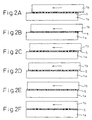
- FIGS. 2A to 2F are schematic views for illustrating operations of the electrostatic motor shown in FIG, 1 and show processes in which the slider electrode member 1b is driven to slide from right to left in the figure with respect to the stator electrode member 1a.
- the projections 5 shown in black in FIGS. 2A to 2F contact each other and function to hold the interval or clearance between the stator electrode member 1a and the slider electrode member 1b.
- the projections 5 shown in white do not contact each other. As shown in FIGS.
- the projections 5 contact each other without bias over the entire facing surfaces of the stator electrode member 1a and the slider electrode member 1b, and the stator electrode member 1a and the slider electrode member 1b are maintained at a predetermined interval.
- FIG. 3 is a sectional view of principal parts of an electrostatic motor built up of a set of a stator electrode member 1a and a slider electrode member 1b according to a second embodiment of the present invention.
- the projections 5 and the cover films 4 are integrally formed.
- the cover films 4 are formed so that projections 5 forming parts of spherical members or elliptical members, etc., are formed on the surfaces of the cover films 4.
- the cover films 4 are attached by a binder to the drive electrode side surfaces of the base films 3 provided with the stator drive electrode patterns 2a and the slider drive electrode patterns 2b, so that they cover the stator drive electrode patterns 2a or the slider drive electrode patterns 2b.
- the stator electrode member 1a and the slider electrode member 1b are produced in this way.
- stator electrode member 1a and the slider electrode member 1b produced in this way are arranged so that the surfaces provided with the projections 5 face each other so as to form the electrostatic motor.
- an insulating liquid such as dimethyl polysiloxane or a fluorocarbon can be interposed in the clearance between the stator electrode member 1a and the slider electrode member 1b.
- FIG. 4 is a sectional view of principal parts of an electrostatic motor built up of a set of a stator electrode member 1a and a slider electrode member 1b according to a third embodiment of the present invention.
- a stator electrode member 1a or a slider electrode member 1b formed by supporting members for forming the drive electrode patterns 2a or 2b in the air and in that state molding an insulating material 6 around them.
- the mold used for such a molding process is provided with shapes corresponding to the projections 5 of the molded article so that the projections 5 are integrally formed with the electrode member.
- the insulative support members are preferably formed from a material of the same type as the insulating material to be molded so that the insulative support members fuse well with the insulating material.
- a material to be molded use is made of a material solidified by chemical reaction, for example, an epoxy resin.
- An insulating filler is mixed according to need to thereby improve the strength, rigidity, and dimensional stability.
- a plastic resin such as a polyester resin or a melted glass material.
- a powder of for example alumina or zirconia may be used and shaped by sintering.
- the stator electrode member 1a and slider electrode member 1b obtained in this way are used to form an electrostatic motor.
- an insulating liquid may be interposed in the clearance between the stator electrode member 1a and the slider electrode member 1b.
- FIGS. 5A to 5C are views for illustrating an electrostatic motor according to a fourth embodiment of the present invention.
- the electrostatic motor according to the fourth embodiment is an example of a linear electrostatic motor and is different from the electrostatic motors according to the first to third embodiment in that ridge-shaped projections 5', in place of the projections 5 forming parts of spherical members or elliptical members, etc., of the first to third embodiments, are provided on the facing surface of the stator electrode member 1a or the slider electrode member 1b.
- the ridge-shaped projections 5' may be provided on both surfaces as well.
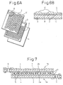
- FIG. 5A is a perspective view of an electrode member 1 which constitutes the stator electrode member 1a or the slider electrode member 1b and which is arranged so that the side where the drive electrode patterns 2a or 2b are provided faces upward.
- the surface of the cover film 4 on the side provided with the drive electrode patterns 2a, 2b is provided with ridge-shaped projections 5'.
- the plurality of ridge-shaped projections 5' shown in FIG. 5A are arranged in parallel at predetermined intervals. Further, the top ends of the ridge-shaped projections 5' are formed to be flat or slightly rounded.
- the ridge-shaped projections 5' provided on the stator electrode member 1a and the ridge-shaped projections 5' provided on the slider electrode member 1b are also formed skewed.
- FIG. 5B is a diagrammatic view showing a stator electrode member 1a and a slider electrode member 1b formed so that the ridge-shaped projections 5' provided on the stator electrode member 1a and the ridge-shaped projections 5' provided on the slider electrode member 1b are skewed by 180 degrees. Since the ridge-shaped projections 5' are formed to extend in an undulated form, the ridge-shaped projections 5' of one electrode member do not fitted in valley portions formed between adjacent ridge-shaped projections 5' of the other electrode member, and the slider electrode member 1b relatively slides with respect to the stator electrode member 1a in a state where the top surfaces of the ridge-shaped projections 5' of the facing electrode members contact each other.
- an electrostatic motor is formed.
- the ridge-shaped projections 5' of the stator electrode member 1a and the slider electrode member 1b need not be skewed by 180 degrees with respect to each other as shown in FIG. 58. It is sufficient so far as a certain extent of inclination exists so that the ridge-shaped projections 5' of one electrode member do not fit in the valley portions formed between the ridge-shaped projections 5' of the other electrode member. Further, it is also possible even if the ridge-shaped projections 5' are not formed to extend in an undulated form as shown in FIGS. 5A to 5C, but are formed to extend straightly.
- a skew may be given so that lines of the ridge-shaped projections 5' of the stator electrode member 1a extend across lines of the ridge-shaped projections 5' of the slider electrode member 1b when the stator electrode member 1a and the slider electrode member 1b are arranged facing each other.
- FIGS. 6A and 6B are views for illustrating the configuration of the electrode members 1 used as the stator electrode member 1a and the slider electrode member 1b according to the fourth embodiment.
- FIG. 6A is an exploded view of the electrode member 1
- FIG. 68 is a sectional view of the portion indicated by "A" in FIG. 6A.
- Cover films 4 formed from a polyimide are attached by a binder such as an epoxy binder etc. to two surfaces of a base film 3 of a polyimide provided with the drive electrode patterns 2.
- a cover film 4 having a surface thereof formed with ridge-shaped projections 5' is attached by a binder to the side of the base film 3 where the drive electrode patterns 2 are provided.
- reference numeral 8 in FIG. 6B shows the layer of the binder.
- an insulating liquid can be interposed in the clearance between the stator electrode member 1a and the slider electrode member 1b.
- FIG. 7 is a sectional view of principal parts of an electrostatic motor built up of a set of a stator electrode member 1a and a slider electrode member 1b according to a fifth embodiment of the present invention.
- one of the stator electrode member 1a and the slider electrode member 1b has projections 5 fixed thereto, while the other is not provided with any projections 5.
- one electrode member has a cover film 4 to which projections 5 made of polyimide are affixed, while the other electrode member has a cover film 4 made of polyimide having a flat surface.
- a material having a low surface energy such as polytetrafluoroethylene (PTFE) is sputtered to one cover film 4, while an inorganic material is attached to the other cover film 4 so as to reduce mutual reactivity.
- PTFE polytetrafluoroethylene
- an insulating liquid can be interposed in the clearance between the stator electrode member 1a and the slider electrode member 1b.
- FIG. 8 is a sectional view of principal parts of an electrostatic motor built up of a set of a stator electrode member 1a and a slider electrode member 1b according to a sixth embodiment of the present invention.
- one of the stator electrode member 1a and the slider electrode member 1b uses a cover film 4 with which projections 5 are integrally formed or has the projections 5 integrally formed with the electrode member by molding as in the third embodiment shown in FIG. 4.
- the other electrode member uses a flat cover film 4 or is formed with flat surface by molding. Note that both electrode members may be provided with projections 5.
- the stator electrode member 1a is formed by attaching a flat cover film 4 to the base film 3 provided with the drive electrode patterns 2 by a binder, while the slider electrode member 1b is prepared by molding and the projections 5 are integrally formed on the surface of the slider electrode member 1b facing the stator electrode member 1a.
- the flat cover film 4 is formed from polyethylene, while the molded material having the projections 5 and the cover film 4 are formed from a polyimide. Further, in order to prevent the abrasion and sticking when both electrode members in contact with each other slide, as in the fifth embodiment, a material having a low surface energy such as PTFE is sputtered to one of the two electrode members, and an inorganic material is attached to the other of them in order to reduce the mutual reactivity. Alternatively, a material having the above effect can be used as the material of the cover film 4 etc. In the sixth embodiment as well, as in the above embodiments, an insulating liquid can be interposed in the clearance between the stator electrode member 1a and the slider electrode member 1b.
- FIG. 9 is a perspective view of an electrostatic motor according to a seventh embodiment of the present invention.
- the seventh embodiment shows an example of a rotation type electrostatic motor constituted by stacking a plurality of sets of stator electrode members 1a and slider electrode members 1b.
- the stator electrode member 1a is arranged so that the side where the drive electrode patterns 2a are provided faces upward, while the slider electrode member 1b is arranged so that the side where the drive electrode patterns 2b are provided faces downward. Further, ridge-shaped projections 5' are formed on the drive electrode pattern side of the slider electrode member 1b, while ridge-shaped projections 5' are deliberately not formed on the surface of the stator electrode member 1a facing the slider electrode member 1b.
- the drive electrode patterns 2a and 2b of the stator electrode member 1a and the slider electrode member 1b of the rotary electrostatic motor are arranged about the rotation center thereof to extend radially as shown in FIG. 9.
- These drive electrode patterns 2a and 2b are prepared by using printed circuit board production technology. For this reason, the conductive portions of the drive electrode patterns project out from the base film 3. Further, when bonding cover films 4 to the surfaces where such drive electrode patterns 2a and 2b are provided, the shapes of the drive electrode patterns 2a and 2b push up the surfaces of the cover films 4. Namely, as a result, radially extending ridge-shaped projections 5' appear on the surfaces of the cover films 4.
- the adhesion layer is made thick between the conductors of the slider drive electrode patterns 2b so as to eliminate the step difference between the slider drive electrode patterns 2b and the rest of the surface of the base film 3 and then cover film 4 is attached to the base film 3.
- the opposite surface of the cover film 4 is formed with ridge-shaped projections 5' skewed with respect to the direction of the radially extending conductors of the slider drive electrode pattern 2b.
- the stator electrode member 1a is formed with ridge-shaped projections of the same pattern as the stator drive electrode patterns 2a due to the thickness of the stator drive electrode patterns 2a, and these ridge-shaped projections formed on the stator electrode member 1a and the ridge-shaped projections 5' formed on the slider electrode member 1b face and contact each other.
- the ridge-shaped projections 5' of the slider electrode member 1b are skewed, the ridge-shaped projections 5' of the slider electrode member 1b will not fit in the valley portions formed between the ridge-shaped projections of the opposite stator electrode member 1a.
- the stacked sets of stator electrode members 1a and slider electrode members 1b may be placed in an insulating liquid of dimethylpolysiloxane or a fluorocarbon etc. so as to make the insulating liquid be interposed in the clearance between the stator electrode member 1a and the slider electrode member 1b
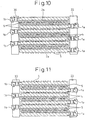
- FIG. 10 is a sectional view of an electrostatic motor according to an eighth embodiment of the present invention wherein a plurality of sets of stator electrode members 1a and slider electrode members 1b are stacked to generate a large torque.
- the stator electrode member 1a and the slider electrode member 1b are fixed to a stator frame 20 and a slider frame 30, respectively.
- the stator electrode members 1a and the slider electrode members 1b are alternately superimposed to constitute the electrostatic motor. Therefore, only one of the stator electrode member 1a and the slider electrode member 1b is formed with the projections 5 on both surfaces, while both surfaces of the other electrode member are flattened.
- FIG. 10 is a sectional view of an electrostatic motor according to an eighth embodiment of the present invention wherein a plurality of sets of stator electrode members 1a and slider electrode members 1b are stacked to generate a large torque.
- the stator electrode member 1a and the slider electrode member 1b are fixed to a stator frame 20 and a slider frame 30, respectively.
- the projections 5 are formed on both the surfaces of the stator electrode members 1a, while both the surfaces of the slider electrode members 1b are flat. Note that it is not necessary to provide the projections 5 on the outermost surfaces of the stacked electrode members 1 (surfaces which do not face any electrode members 1). In the example shown in FIG. 10, the projections 5 are also provided on the bottom surface of the stator electrode member 1a in the lowermost layer, but accordingly it is not always necessary to provide the projections 5 on this surface.
- FIG. 11 is a sectional view of an electrostatic motor according to a ninth embodiment of the present invention similar to the eighth embodiment of the present invention, wherein a plurality of sets of stator electrode members 1a and slider electrode members 1b are stacked to generate a large torque.
- projections 5 are provided on only one surface of each of the stator electrode members 1a and the slider electrode members 1b.
- the stator electrode members 1a and the slider electrode members 1b are alternately superimposed and fixed to the stator frame 20 and the slider frame 30, respectively.
- An electrostatic motor is thus constituted.
- FIG. 11 is a sectional view of an electrostatic motor according to a ninth embodiment of the present invention similar to the eighth embodiment of the present invention, wherein a plurality of sets of stator electrode members 1a and slider electrode members 1b are stacked to generate a large torque.
- projections 5 are provided on only one surface of each of the stator electrode members 1a and the slider electrode members 1b.
- the stator electrode members 1a and the slider electrode members 1b are
- the surfaces of the stator electrode members 1a where the stator drive electrode patterns 2a are formed are provided with the projections 5, while the surfaces of the slider electrode members 1b opposite to where the slider drive electrode patterns 2b are formed are provided with the projections 5.
- the electrostatic motor is constituted by alternately superimposing such stator electrode members 1a and slider electrode members 1b. The clearances between the stator electrode members 1a and the slider electrode members 1b are maintained by these projections 5, so that the slider electrode members 1b relatively slide with respect to the stator electrode members 1a while contacting these projections 5 on the flat surface.
- these stacked stator electrode members 1a and slider electrode members 1b may be placed in an insulating liquid to cause the insulating liquid to be interposed in the clearances between the stator electrode members 1a and the slider electrode members 1b.
- an insulating gas may be filled in the clearances between the facing surfaces of the stator electrode members 1a and the slider electrode members 1b or the insulating liquid may be filled in it.
- the insulating liquid use is made of for example dimethyl polysiloxane or a fluorocarbon.
- the members constituting the portions where the stator electrode members 1a and the slider electrode members 1b contact that is, the projections 5 and the surfaces contacting the projections 5 (cover film 4), are preferably formed by a polyimide or a fluororesin excellent in sliding property.
Landscapes
- Micromachines (AREA)
- Linear Motors (AREA)
Applications Claiming Priority (2)
| Application Number | Priority Date | Filing Date | Title |
|---|---|---|---|
| JP2004089479 | 2004-03-25 | ||
| JP2004089479A JP4146813B2 (ja) | 2004-03-25 | 2004-03-25 | 静電モータ |
Publications (2)
| Publication Number | Publication Date |
|---|---|
| EP1580876A2 true EP1580876A2 (de) | 2005-09-28 |
| EP1580876A3 EP1580876A3 (de) | 2007-05-09 |
Family
ID=34858464
Family Applications (1)
| Application Number | Title | Priority Date | Filing Date |
|---|---|---|---|
| EP05006268A Withdrawn EP1580876A3 (de) | 2004-03-25 | 2005-03-22 | Elektrostatischmotor |
Country Status (4)
| Country | Link |
|---|---|
| US (1) | US7304410B2 (de) |
| EP (1) | EP1580876A3 (de) |
| JP (1) | JP4146813B2 (de) |
| CN (1) | CN1674428A (de) |
Cited By (1)
| Publication number | Priority date | Publication date | Assignee | Title |
|---|---|---|---|---|
| ITTO20080603A1 (it) * | 2008-07-31 | 2010-02-01 | St Microelectronics Srl | Micromotore elettrostatico con statore e rotore a contatto, in particolare per sistemi di memorizzazione probe storage |
Families Citing this family (18)
| Publication number | Priority date | Publication date | Assignee | Title |
|---|---|---|---|---|
| JP3886494B2 (ja) * | 2004-01-23 | 2007-02-28 | ファナック株式会社 | 固定子用及び移動子用のフィルム型電極及び静電モータ |
| JP4015119B2 (ja) * | 2004-01-23 | 2007-11-28 | ファナック株式会社 | 静電モータ |
| JP4146813B2 (ja) * | 2004-03-25 | 2008-09-10 | ファナック株式会社 | 静電モータ |
| US20060214535A1 (en) * | 2005-03-22 | 2006-09-28 | Salmon Peter C | Energy converter utilizing electrostatics |
| JP4008453B2 (ja) * | 2005-04-13 | 2007-11-14 | ファナック株式会社 | 静電モータ用電極の製造方法、静電モータ用電極及び静電モータ |
| JP4621577B2 (ja) * | 2005-10-27 | 2011-01-26 | アルプス電気株式会社 | 静電アクチュエータ及びその駆動方法 |
| JP4810571B2 (ja) * | 2006-05-18 | 2011-11-09 | アルプス電気株式会社 | 静電アクチュエータ |
| JP5081833B2 (ja) * | 2006-10-30 | 2012-11-28 | 三洋電機株式会社 | 静電動作装置 |
| JP5028185B2 (ja) * | 2007-08-28 | 2012-09-19 | 三洋電機株式会社 | 静電発電装置 |
| JP5733964B2 (ja) * | 2009-12-24 | 2015-06-10 | キヤノン株式会社 | 高分子アクチュエータ |
| JP5609271B2 (ja) * | 2010-05-28 | 2014-10-22 | 大日本印刷株式会社 | 静電アクチュエータ |
| US20120268386A1 (en) * | 2011-04-19 | 2012-10-25 | Karamath James Robert | Touch-screen device including tactile feedback actuator |
| US9184676B2 (en) * | 2011-10-31 | 2015-11-10 | Wisconsin Alumni Research Foundation | Varying capacitance rotating electrical machine |
| US9479085B1 (en) | 2012-09-15 | 2016-10-25 | C-Motive Technologies Inc. | Self-conforming plates for capacitive machines such as electrostatic motors and generators |
| US10504656B2 (en) * | 2015-04-29 | 2019-12-10 | General Electric Company | Electrodes for linear switched capacitive devices |
| US9748867B2 (en) * | 2015-08-03 | 2017-08-29 | General Electric Company | Control system for linear switched capacitive devices |
| CN110855177A (zh) * | 2019-11-21 | 2020-02-28 | 南方科技大学 | 一种柔性薄膜直线电机 |
| EP4085521A4 (de) | 2020-01-03 | 2024-03-06 | C-Motive Technologies Inc. | Elektrostatischer motor mit flüssigkeitsmanagement-eigenschaften |
Family Cites Families (13)
| Publication number | Priority date | Publication date | Assignee | Title |
|---|---|---|---|---|
| JP2814582B2 (ja) * | 1989-07-07 | 1998-10-22 | 富士通株式会社 | 液体電極型静電モータ |
| JPH04340371A (ja) * | 1990-06-05 | 1992-11-26 | Mitsubishi Kasei Corp | 静電アクチュエータ |
| JPH04207981A (ja) * | 1990-11-30 | 1992-07-29 | Masafumi Yano | 静電気力を利用した動力発生装置 |
| JP2700992B2 (ja) * | 1993-10-28 | 1998-01-21 | 日本メクトロン株式会社 | 平面マイクロアクチュエ−タ− |
| US5531844A (en) * | 1994-02-14 | 1996-07-02 | The United States Of America As Represented By The Secretary Of The Navy | Energetic compositions containing no volatile solvents |
| JPH0851786A (ja) * | 1994-08-08 | 1996-02-20 | Yaskawa Electric Corp | 静電モータ |
| JPH09121563A (ja) * | 1995-10-25 | 1997-05-06 | Mitsubishi Chem Corp | 静電アクチュエータ |
| JPH10225145A (ja) * | 1997-02-13 | 1998-08-21 | Oki Electric Ind Co Ltd | 媒体搬送装置 |
| US6359367B1 (en) * | 1999-12-06 | 2002-03-19 | Acuson Corporation | Micromachined ultrasonic spiral arrays for medical diagnostic imaging |
| JP2001178154A (ja) * | 1999-12-14 | 2001-06-29 | Toto Ltd | 静電アクチュエータ及びその製造方法 |
| EP1158332A1 (de) * | 1999-12-27 | 2001-11-28 | Ngk Insulators, Ltd. | ANZEIGEVORRICHTUNG UND DAZUGEHöRIGES HERSTELLUNGSVERFAHREN |
| AU2003217198A1 (en) * | 2002-01-11 | 2003-07-30 | Npoint, Inc. | Dielectric actuator including conductive gap |
| JP4146813B2 (ja) * | 2004-03-25 | 2008-09-10 | ファナック株式会社 | 静電モータ |
-
2004
- 2004-03-25 JP JP2004089479A patent/JP4146813B2/ja not_active Expired - Fee Related
-
2005
- 2005-03-22 EP EP05006268A patent/EP1580876A3/de not_active Withdrawn
- 2005-03-25 US US11/089,150 patent/US7304410B2/en not_active Expired - Fee Related
- 2005-03-25 CN CN200510058967.6A patent/CN1674428A/zh active Pending
Cited By (2)
| Publication number | Priority date | Publication date | Assignee | Title |
|---|---|---|---|---|
| ITTO20080603A1 (it) * | 2008-07-31 | 2010-02-01 | St Microelectronics Srl | Micromotore elettrostatico con statore e rotore a contatto, in particolare per sistemi di memorizzazione probe storage |
| US8466599B2 (en) | 2008-07-31 | 2013-06-18 | Stmicroelectronics S.R.L. | Electrostatic micromotor with stator and rotor in contact, in particular for probe-storage systems |
Also Published As
| Publication number | Publication date |
|---|---|
| JP4146813B2 (ja) | 2008-09-10 |
| US20050212382A1 (en) | 2005-09-29 |
| CN1674428A (zh) | 2005-09-28 |
| EP1580876A3 (de) | 2007-05-09 |
| US7304410B2 (en) | 2007-12-04 |
| JP2005278324A (ja) | 2005-10-06 |
Similar Documents
| Publication | Publication Date | Title |
|---|---|---|
| US7304410B2 (en) | Electrostatic motor including projections providing a clearance between stator and slider electrode members | |
| CA2218876C (en) | Elastomeric micro electro mechanical systems | |
| US11101745B2 (en) | Electrostatic actuator | |
| CN103609000B (zh) | 旋转电机、旋转电机用绝缘材料及槽衬 | |
| EP2559146B1 (de) | Vorrichtung zur verwendung als motor oder generator | |
| EP2819293A1 (de) | Gelaktuator und verfahren zur herstellung davon | |
| US20080175733A1 (en) | Embedded fluid mixing device using a homopolar motor | |
| US12160184B2 (en) | Stackable actuating element with profiled insulated electrode structures | |
| JPH05260766A (ja) | 静電アクチュエータ | |
| JP2012509048A (ja) | 電動モータのセグメント化されたステータエレメント/ロータエレメント | |
| US11081977B2 (en) | Vibrational energy harvester device | |
| JPH02285978A (ja) | フィルムを利用した接触型静電アクチュエータ | |
| US11863087B2 (en) | Stackable actuating element with profiled insulated electrode structures | |
| US7372186B2 (en) | Electrostatic motor with clearance maintaining structure | |
| JP3095642B2 (ja) | 静電アクチュエータおよびその駆動方法 | |
| US7230364B2 (en) | Electrostatic motor utilizing static electricity as a drive force | |
| EP1557938A2 (de) | Filmähnliche Elektrode für elektrostatischer Mikromotor | |
| JP3545876B2 (ja) | 静電フィルムアクチュエータ | |
| CN218266653U (zh) | 高分子材料连接结构 | |
| JP3470832B2 (ja) | 静電アクチュエータにおける多層電極配線板、及びその製造方法 | |
| Niino et al. | Dual excitation electrostatic stepping motor | |
| CN115611229A (zh) | 堆栈结构、方法及平坦有源元件层 | |
| JP5309752B2 (ja) | 静電アクチュエータ | |
| JP2007097356A (ja) | 静電モータおよびその製造方法 | |
| JP2009284573A (ja) | 静電アクチュエータ |
Legal Events
| Date | Code | Title | Description |
|---|---|---|---|
| PUAI | Public reference made under article 153(3) epc to a published international application that has entered the european phase |
Free format text: ORIGINAL CODE: 0009012 |
|
| AK | Designated contracting states |
Kind code of ref document: A2 Designated state(s): AT BE BG CH CY CZ DE DK EE ES FI FR GB GR HU IE IS IT LI LT LU MC NL PL PT RO SE SI SK TR |
|
| AX | Request for extension of the european patent |
Extension state: AL BA HR LV MK YU |
|
| PUAL | Search report despatched |
Free format text: ORIGINAL CODE: 0009013 |
|
| AK | Designated contracting states |
Kind code of ref document: A3 Designated state(s): AT BE BG CH CY CZ DE DK EE ES FI FR GB GR HU IE IS IT LI LT LU MC NL PL PT RO SE SI SK TR |
|
| AX | Request for extension of the european patent |
Extension state: AL BA HR LV MK YU |
|
| 17P | Request for examination filed |
Effective date: 20070716 |
|
| AKX | Designation fees paid |
Designated state(s): DE |
|
| STAA | Information on the status of an ep patent application or granted ep patent |
Free format text: STATUS: THE APPLICATION HAS BEEN WITHDRAWN |
|
| 18W | Application withdrawn |
Effective date: 20090128 |