EP1580949A1 - Synchroniseur de phase et de fréquence pour récepteurs OFDM utilisant un préambule, les pilotes et les données d'information - Google Patents
Synchroniseur de phase et de fréquence pour récepteurs OFDM utilisant un préambule, les pilotes et les données d'information Download PDFInfo
- Publication number
- EP1580949A1 EP1580949A1 EP04006933A EP04006933A EP1580949A1 EP 1580949 A1 EP1580949 A1 EP 1580949A1 EP 04006933 A EP04006933 A EP 04006933A EP 04006933 A EP04006933 A EP 04006933A EP 1580949 A1 EP1580949 A1 EP 1580949A1
- Authority
- EP
- European Patent Office
- Prior art keywords
- phase
- frequency
- estimate
- tracking system
- perform
- Prior art date
- Legal status (The legal status is an assumption and is not a legal conclusion. Google has not performed a legal analysis and makes no representation as to the accuracy of the status listed.)
- Granted
Links
- 238000012937 correction Methods 0.000 claims abstract description 68
- 230000001131 transforming effect Effects 0.000 claims abstract description 14
- 238000000034 method Methods 0.000 claims description 47
- 239000013598 vector Substances 0.000 claims description 26
- 230000006870 function Effects 0.000 claims description 13
- 238000004590 computer program Methods 0.000 claims description 11
- 238000012546 transfer Methods 0.000 claims description 10
- 230000008901 benefit Effects 0.000 description 17
- 238000010586 diagram Methods 0.000 description 9
- 230000005540 biological transmission Effects 0.000 description 7
- 230000008859 change Effects 0.000 description 6
- 230000000694 effects Effects 0.000 description 4
- 239000000969 carrier Substances 0.000 description 3
- 230000008569 process Effects 0.000 description 3
- 125000004122 cyclic group Chemical group 0.000 description 1
- 238000013461 design Methods 0.000 description 1
- 239000000284 extract Substances 0.000 description 1
- 238000005259 measurement Methods 0.000 description 1
- 238000012986 modification Methods 0.000 description 1
- 230000004048 modification Effects 0.000 description 1
- 230000000750 progressive effect Effects 0.000 description 1
- 230000007704 transition Effects 0.000 description 1
Images


Classifications
-
- H—ELECTRICITY
- H04—ELECTRIC COMMUNICATION TECHNIQUE
- H04L—TRANSMISSION OF DIGITAL INFORMATION, e.g. TELEGRAPHIC COMMUNICATION
- H04L27/00—Modulated-carrier systems
- H04L27/26—Systems using multi-frequency codes
- H04L27/2601—Multicarrier modulation systems
- H04L27/2647—Arrangements specific to the receiver only
- H04L27/2655—Synchronisation arrangements
- H04L27/2657—Carrier synchronisation
- H04L27/266—Fine or fractional frequency offset determination and synchronisation
-
- H—ELECTRICITY
- H04—ELECTRIC COMMUNICATION TECHNIQUE
- H04L—TRANSMISSION OF DIGITAL INFORMATION, e.g. TELEGRAPHIC COMMUNICATION
- H04L27/00—Modulated-carrier systems
- H04L27/26—Systems using multi-frequency codes
- H04L27/2601—Multicarrier modulation systems
- H04L27/2647—Arrangements specific to the receiver only
- H04L27/2655—Synchronisation arrangements
- H04L27/2668—Details of algorithms
- H04L27/2673—Details of algorithms characterised by synchronisation parameters
- H04L27/2676—Blind, i.e. without using known symbols
- H04L27/2679—Decision-aided
-
- H—ELECTRICITY
- H04—ELECTRIC COMMUNICATION TECHNIQUE
- H04L—TRANSMISSION OF DIGITAL INFORMATION, e.g. TELEGRAPHIC COMMUNICATION
- H04L27/00—Modulated-carrier systems
- H04L27/0014—Carrier regulation
- H04L2027/0024—Carrier regulation at the receiver end
- H04L2027/0026—Correction of carrier offset
- H04L2027/003—Correction of carrier offset at baseband only
-
- H—ELECTRICITY
- H04—ELECTRIC COMMUNICATION TECHNIQUE
- H04L—TRANSMISSION OF DIGITAL INFORMATION, e.g. TELEGRAPHIC COMMUNICATION
- H04L27/00—Modulated-carrier systems
- H04L27/0014—Carrier regulation
- H04L2027/0044—Control loops for carrier regulation
- H04L2027/0053—Closed loops
- H04L2027/0061—Closed loops remodulation
-
- H—ELECTRICITY
- H04—ELECTRIC COMMUNICATION TECHNIQUE
- H04L—TRANSMISSION OF DIGITAL INFORMATION, e.g. TELEGRAPHIC COMMUNICATION
- H04L27/00—Modulated-carrier systems
- H04L27/0014—Carrier regulation
- H04L2027/0083—Signalling arrangements
- H04L2027/0089—In-band signals
- H04L2027/0093—Intermittant signals
- H04L2027/0095—Intermittant signals in a preamble or similar structure
-
- H—ELECTRICITY
- H04—ELECTRIC COMMUNICATION TECHNIQUE
- H04L—TRANSMISSION OF DIGITAL INFORMATION, e.g. TELEGRAPHIC COMMUNICATION
- H04L27/00—Modulated-carrier systems
- H04L27/26—Systems using multi-frequency codes
- H04L27/2601—Multicarrier modulation systems
- H04L27/2647—Arrangements specific to the receiver only
- H04L27/2655—Synchronisation arrangements
- H04L27/2657—Carrier synchronisation
- H04L27/2659—Coarse or integer frequency offset determination and synchronisation
-
- H—ELECTRICITY
- H04—ELECTRIC COMMUNICATION TECHNIQUE
- H04L—TRANSMISSION OF DIGITAL INFORMATION, e.g. TELEGRAPHIC COMMUNICATION
- H04L27/00—Modulated-carrier systems
- H04L27/26—Systems using multi-frequency codes
- H04L27/2601—Multicarrier modulation systems
- H04L27/2647—Arrangements specific to the receiver only
- H04L27/2655—Synchronisation arrangements
- H04L27/2668—Details of algorithms
- H04L27/2673—Details of algorithms characterised by synchronisation parameters
- H04L27/2675—Pilot or known symbols
Definitions
- the present invention relates in a first aspect to a tracking system comprised in an OFDM receiver.
- the present invention relates to a method for tracking rapid changes in frequency and phase offset in an OFDM receiver.
- the present invention relates to at least one computer program product for tracking rapid changes in frequency and phase offset in an OFDM receiver.
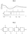
- FIG. 1 A well-known issue in designing transceiver systems in which rapid transitions must be made between e.g. receive and transmit states or between idle and receive states, is that the local oscillators on the system can suffer a perturbation from their stable operating frequency. This can, for example, be due to a sudden change in load on the power supply.
- An example of such a glitch is shown in Figure 1, related to the preamble of an IEEE 802.11 WLAN OFDM transmission.
- 2 denotes the short preamble symbols
- 4 denotes the cyclic prefix (CP) and the long preamble symbols
- 6 denotes the SIGNAL field
- 8 denotes the data symbols.
- the VCO frequency is shown initially at one stable level; when the transmission begins, the operating conditions change and the VCO moves to a different stable operating frequency. Since the VCO operates in a feedback loop, it takes time for the frequency to converge on the new stable operating frequency.
- the first operation in the datapath is to correct the frequency error, which is achieved by a progressively phase rotation of the incoming I / Q samples, which is intended to exactly cancel out the phase rotation of the incoming signal due to the frequency offset.
- the frequency correction is based on the initial frequency estimate.
- This operation is performed in the frequency correction block 10.
- the next operation is to perform a fast Fourier transform (FFT), at the block 12, on the received data.
- FFT fast Fourier transform
- 802.11a OFDM transmission there are 52 sub-carriers, of which 48 are used to transmit data and 4 are pilot tones modulated with a known sequence.
- the sub-carriers extracted by the FFT 12 are demodulated, at the demodulation block 14, (converted from symbols into [soft] data bits).
- the demodulation block 14 In order to perform the demodulation, it is necessary to have an estimate of the channel transfer function for each subcarrier, which is represented by a scaling and a rotation of the transmitted constellation.
- the initial channel estimate is typically obtained during the long preamble symbols.
- error correction at the error correction block 16, is applied to the received data stream.
- a Viterbi decoder is typically used to perform the error correction function.
- D denotes the data outputted from the OFDM receiver.
- a residual frequency error means that the frequency correction block will not completely remove the frequency offset.
- the first problem that this causes is that there is a progressively increasing phase rotation of the received signal at the output of the frequency correction block.
- the demodulation process is based on the received signal phase as estimated during the long preamble.
- the progressive phase rotation caused by the frequency error means that there will be an increasing phase error with respect to the channel estimate. At a certain point, this will lead to uncorrectable demodulation errors.
- An example of this is shown in Figure 3: the unrotated received I / Q vector is shown as a solid line, and is near to the correct constellation point corresponding to the transmitted data.
- E denotes the correct constellation point for received vector
- F denotes all of the ideal constellation points according to channel estimate.
- the subcarriers are perfectly separable from one another (the energy from one subcarrier does not interfere at all with another subcarrier).
- the frequency offset becomes at all large, a significant amount of inter-carrier interference occurs which is visible as noise in the signal at the demodulator.
- phase error of a received I / Q vector can be estimated based on knowledge of the channel estimate and the transmitted constellation point, by directly measuring the angle from the expected constellation point and the actual received vector. This estimate is perturbed by errors in the channel estimate and by noise; an improved estimate for the phase can be obtained in an OFDM symbol by measuring the phase error over a number of subcarriers, possibly also with weighting according to the strength of the subcarrier signals.
- the frequency error is simply the change in the phase estimate with time, and can be estimated by dividing the phase change between two symbols with the symbol period.
- This demodulated data is then re-modulated (mapped back into I / Q constellation points) for each subcarrier in the OFDM symbol, based on the channel estimate. It is then possible to use all of the subcarriers in the OFDM symbol to make an estimate of the overall phase rotation of the OFDM symbol.
- phase error is used as an input to a PID (proportional, integral, derivative) control loop, which uses the instantaneous estimates for the phase and frequency error plus an integral phase term to drive the input to the frequency correction block, thereby simultaneously tracking errors in both phase and frequency.
- PID proportional, integral, derivative
- an IEEE 802.11a OFDM transmission uses only 48 of the 52 subcarriers for carrying data.
- the remaining 4 pilot tones are modulated with a known sequence, and these can therefore be used directly for the measurement of phase error.
- pilot-based phase and frequency tracking An example architecture is shown in Figure 5, called pilot-based phase and frequency tracking.
- the corresponding function blocks in Figures 2, 4 and 5 have been denoted with the same reference signs and will not be explained again.
- phase correction block 22 connected to the block 12 and to the block 14.
- pilot-based phase estimation block 24 connected to the block 10 and to the block 22.
- the pilot-based phase estimation block extracts the pilot subcarriers from the data stream, and uses them to calculate an estimate of the phase rotation for the current OFDM symbol. This estimate of the phase error is then used by the phase correction block, which de-rotates the received symbol prior to demodulation.
- the latency can be reduced.
- the resulting phase error will cause a large number of data estimates to be incorrect. This will have the effect of reducing or even reversing the phase error estimate and will cause the frequency tracking loop to break down.
- the pilot-based method is very robust, since the pilot tones are known in advance and the phase correction is applied immediately, and can therefore cope with large and rapid swings in frequency.
- the problem with the pilot-based solution is the noise introduced by the phase estimate due to it being made over only the 4 pilot subcarriers. This noise directly modulates the received symbol, increasing the error vector magnitude and thereby the error probability.
- the object with the present invention is to solve the above mentioned problems. This is achieved with a tracking system according to claim 1.
- the tracking system according to the present invention is comprised in an OFDM receiver.
- the tracking system is operable to track rapid changes in frequency and phase offset of the received signal.
- the tracking system comprises a frequency correction means operable to correct a frequency error of a received OFDM symbol.
- the tracking system also comprises a to said frequency correction means connected transforming means operable to perform a Fourier transform operation resulting in a number of independently modulated subcarriers.
- the tracking system also comprises a to said transforming means connected first estimating means operable to perform an initial coarse estimate of the phase of the received OFDM symbol, based on the phase of one or more subcarriers carrying pilot tones.
- the tracking system also comprises a to said first estimating means connected first phase correction means operable to perform an initial correction of the symbol phase.
- the tracking system also comprises a to said first phase correction means connected second estimating means operable to perform a data-driven phase estimation on the corrected symbol resulting in a refined phase estimate.
- the tracking system also comprises a to said second estimating means connected phase and frequency tracking means.
- An advantage with the tracking system according to the present invention is that it gives phase- and frequency-tracking which has the robustness of pilot-based phase and frequency tracking, while having the low estimation noise available from using data-driven tracking over all subcarriers. While the estimation noise is not quite as low as that available from the post-Viterbi derived estimate, due to possible demodulation errors, experience has shown that performance is acceptable. Also, the use of the soft decisions from demodulation to weight the contributions to the channel estimates improves performance.
- a further advantage in this connection is achieved if said tracking system also comprises a to said first phase correction means connected first demodulating means operable to demodulate said phase-corrected OFDM symbol to produce a data stream, and a to said demodulating means connected remodulating means operable to remodulate said data stream, which remodulating means also is connected to said second estimating means.
- said tracking system also comprises a second phase correction means connected to said second estimating means and to said transforming means, which second phase correction means is operable to perform a more precise correction of the received OFDM symbol phase.
- phase and frequency tracking means comprises a to said second phase correction means connected second demodulating means, which in turn is connected to an error correction means resulting in said final estimate of the received data sequence.
- a further advantage in this connection is achieved if said tracking system also comprises a first weighting means operable to weight the contribution to the estimate of the OFDM symbol phase from each subcarrier according to the strength of that subcarrier.
- said tracking system also comprises a second weighting means operable to weight the phase estimate from each subcarrier according to a distance between a received I - Q vector and the nearest constellation point.
- a further advantage in this connection is achieved if the distance between the received I - Q vector and the nearest constellation point is used to weight the contribution to the overall phase estimate from this subcarrier such that received I-Q vectors with lower probability of being associated with the constellation point contribute less.
- the above mentioned problems are also solved with a method for tracking rapid changes in frequency and phase offset in an OFDM receiver according to claim 9.
- the method comprises the steps:
- the proposed method gives phase- and frequency-tracking which has the robustness of pilot-based phase and frequency tracking, while having the low estimation noise available from using data-driven tracking over all subcarriers. While the estimation noise is not quite as low as that available from the post-Viterbi derived estimate, due to possible demodulation errors, experience has shown that performance is acceptable. Also, the use of the soft decisions from demodulation to weight the contributions to the channel estimates improves performance.
- a further advantage in this connection is achieved if the weighting is such that the lower the probability that the received I - Q vector belongs to the nearest constellation point, the smaller is the contribution to the overall phase estimate for this subcarrier.
- the above mentioned problems are also solved with at least one computer program product according to claim17.
- the at least one computer program product directly loadable into the internal memory of at least one digital computer, comprising software code portions for performing the steps of claim 9 when said at least one product is/are run on said at least one computer.
- An advantage with the at least one computer program product is that it gives phase- and frequency-tracking which has the robustness of pilot-based phase and frequency tracking, while having the low estimation noise available from using data-driven tracking over all subcarriers. While the estimation noise is not quite as low as that available from the post-Viterbi derived estimate, due to possible demodulation errors, experience has shown that performance is acceptable. Also, the use of the soft decisions from demodulation to weight the contributions to the channel estimates improves performance.
- FIG 6 there is disclosed a block diagram of a tracking system 100 according to the present invention.
- the tracking system 100 is comprised in an OFDM receiver 300, which only is disclosed diagrammatically in Figure 6.
- the tracking system 100 is operable to track rapid changes in frequency and phase offset of the received signal.
- the tracking system 100 comprises a frequency correction means 102 operable to correct a frequency error of a received OFDM symbol, A, i.e. I/Q Rx samples.
- a transforming means 104 is connected to said frequency correcting means 102, which transforming means 104 is operable to perform a Fourier transform operation resulting in a number of independently modulated subcarriers.
- the tracking system 100 also comprises a to said transforming means 104 connected first estimating means 106 operable to perform an initial coarse estimate of the phase of the received OFDM symbol, based on the phase of one or more subcarriers carrying pilot tones.
- the tracking system 100 also comprises a to said first estimating means 106 connected first phase correction means 108 operable to perform an initial correction of the symbol phase.
- a second estimating means 110 is connected to said first phase correction means 108, which second estimating means 110 is operable to perform a data-driven phase estimation on the corrected symbol resulting in a refined phase estimate.
- the reference signs A, B, C and D has the same meaning as in Figures 2, 4 and 5.
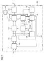
- FIG 7 there is disclosed a more detailed block diagram of the tracking system 100 disclosed in Figure 6. Some of the means/functional blocks in Figure 7 corresponds to the same means/functional blocks and these have been allocated the same reference signs in both Figure 6 and Figure 7 and will not be described again.
- the tracking system 100 disclosed in Figure 7 also comprises a to said first phase correction means 108 connected first demodulating means 114 operable to demodulate said phase corrected OFDM symbol to produce a data stream.
- a remodulating means 116 is connected to said demodulating means 114, which remodulating means 116 is operable to remodulate said data stream. As is apparent from Figure 7, said remodulating means 116 is also connected to said second estimating means 110.
- the tracking system 100 also comprises a to said transforming means 104 connected second demodulating means 118, which in turn is connected to an error correction means 120 resulting in said final estimate of the received data sequence.
- the tracking system 100 can also comprise a second phase correction means 122, disclosed with a dotted line, connected to said second estimating means 110, to said transforming means 104 and to said second demodulating means 118.
- the second phase correction means 122 is operable to perform a more precise correction of the received OFDM symbol phase.
- a first weighting means 124 operable to weight the contribution to the estimate of the OFDM symbol phase from each subcarrier according to the strength of the subcarrier.
- a second weighting means 126 operable to weight the contribution to the phase estimate from each subcarrier according to a distance between the received I-Q vector and the nearest constellation point for that subcarrier, such that received I-Q vectors with smaller probability of being associated to the nearest constellation point have a smaller contribution to the overall estimate from this subcarrier.
- said first demodulating means 114 and said second demodulating means 118 are provided with an initial estimate of the channel transfer function for each subcarrier.
- the invention combines an initial estimation and correction of the phase of the received OFDM symbol, based on the phase of the pilot subcarriers, with a subsequent refined phase estimation based on demodulated data (without error correction).
- This refined phase estimation can then be used as the basis for conventional frequency and phase tracking (e.g. via a PID loop) as well as for phase correction of the OFDM symbol prior to demodulation if so desired.
- a pilot-based phase estimation block After the FFT, a pilot-based phase estimation block generates an initial phase estimate of the OFDM symbol phase, based on the phase of the pilots. This initial phase estimate is used by the phase correction block to perform a first phase correction of the OFDM symbol.
- the phase-corrected OFDM symbol is then demodulated to produce a data stream, which passes directly into a remodulation block.
- the remodulated I-Q vector for each subcarrier corresponds to the ideal constellation point given the transmitted I-Q vector and the channel estimate for that subcarrier.
- phase estimate can then be used for phase and frequency tracking (e.g. in a conventional PID loop).
- the phase estimate is also used to perform a more precise correction of the received OFDM symbol phase. This improves robustness to very sudden frequency shifts. Since the phase estimate has low noise, this phase correction does not degrade the error vector magnitude seen at the demodulator in the same way as it does when the phase estimation is based only on the pilot subcarriers.
- phase-corrected OFDM symbol then passes through demodulation and error correction processes to provide the final estimate of the received data sequence. Note that, if the additional robustness to sudden frequency changes is not required (e.g. if the frequency / phase tracking can respond sufficiently quickly to expected frequency transients), the final phase correction may not be necessary.
- Errors in demodulation can result due to noise and errors in the initial phase estimate. The effect of this will be that the wrong constellation point will be selected (the process of demodulation can be thought of as simply choosing the "nearest" constellation point to the received I-Q vector). These errors will disturb the overall phase estimate to some extent. However the effects of these errors can be minimised by a number of techniques applied when calculating the data-based phase estimate.
- FIG 8 there is disclosed a flow chart of the method for tracking rapid changes in frequency and phase offset in an OFDM receiver.
- the method begins at block 150.
- the method continues, at block 152, with the step: to correct a frequency error of a received OFDM symbol.
- the method continues, at block 154, with the step: to perform a Fourier transform operation resulting in a number of independently modulated subcarriers.
- the method continues, at block 156, with the step: to perform an initial coarse estimate of the phase of the received OFDM symbol, based on the phase of one or more subcarriers carrying pilot tones.
- the method continues, at block 158, with the step: to perform an initial correction of the symbol phase.
- the method continues, at block 160, with the step: to perform a data-driven phase estimation on the corrected symbol resulting in a refined phase estimate. Thereafter the method continues, at block 162, with the step: to perform a phase and frequency tracking to provide a final estimate of the received data sequence. The method is finished at block 164.
- said method also comprises the steps:
- said method also comprises the step:
- said method also comprises the step:
- said method also comprises the step:
- said method also comprises the step:
- said method also comprises the step:
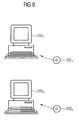
- FIG 9 there is disclosed a schematic diagram of some computer program products according to the present invention.
- n different digital computers 200 1 , ..., 200 n wherein n is an integer.
- n different computer program products 202 1 , ..., 202 n here showed in the form of compact discs.
- the different computer program products 202 1 , ..., 202 n are directly loadable into the internal memory of the n different digital computers 200 1 , ..., 200 n .
- Each computer program product 202 1 , ..., 202 n comprises software code portions for performing some or all the steps of figure 9 when the product (s) 202 1 ..., 202 n is/are run on said computer (s) 200 1 ..., 200 n .
- Said computer program products 202 1 , ..., 202 n can e. g. be in the form of floppy disks, RAM disks, magnetic tapes, opto magnetical disks or any other suitable products.
Landscapes
- Engineering & Computer Science (AREA)
- Computer Networks & Wireless Communication (AREA)
- Signal Processing (AREA)
- Synchronisation In Digital Transmission Systems (AREA)
- Digital Transmission Methods That Use Modulated Carrier Waves (AREA)
Priority Applications (4)
| Application Number | Priority Date | Filing Date | Title |
|---|---|---|---|
| EP04006933A EP1580949B1 (fr) | 2004-03-23 | 2004-03-23 | Synchroniseur de phase et de fréquence pour récepteurs OFDM utilisant un préambule, des pilotes et des données d'information |
| DE602004015929T DE602004015929D1 (de) | 2004-03-23 | 2004-03-23 | Phasen- und Frequenzsynchronisationseinrichtung für OFDM-Empfänger unter Verwendung von einer Präambel, Piloten und Informationsdaten |
| US11/086,504 US7480337B2 (en) | 2004-03-23 | 2005-03-22 | Tracking system comprised in an OFDM receiver |
| CN2005100561806A CN1674573B (zh) | 2004-03-23 | 2005-03-23 | 正交频分复用接收器中的跟踪系统 |
Applications Claiming Priority (1)
| Application Number | Priority Date | Filing Date | Title |
|---|---|---|---|
| EP04006933A EP1580949B1 (fr) | 2004-03-23 | 2004-03-23 | Synchroniseur de phase et de fréquence pour récepteurs OFDM utilisant un préambule, des pilotes et des données d'information |
Publications (2)
| Publication Number | Publication Date |
|---|---|
| EP1580949A1 true EP1580949A1 (fr) | 2005-09-28 |
| EP1580949B1 EP1580949B1 (fr) | 2008-08-20 |
Family
ID=34854591
Family Applications (1)
| Application Number | Title | Priority Date | Filing Date |
|---|---|---|---|
| EP04006933A Expired - Lifetime EP1580949B1 (fr) | 2004-03-23 | 2004-03-23 | Synchroniseur de phase et de fréquence pour récepteurs OFDM utilisant un préambule, des pilotes et des données d'information |
Country Status (4)
| Country | Link |
|---|---|
| US (1) | US7480337B2 (fr) |
| EP (1) | EP1580949B1 (fr) |
| CN (1) | CN1674573B (fr) |
| DE (1) | DE602004015929D1 (fr) |
Cited By (5)
| Publication number | Priority date | Publication date | Assignee | Title |
|---|---|---|---|---|
| WO2007137281A3 (fr) * | 2006-05-22 | 2008-07-10 | Qualcomm Inc | Correction de phase pour transmissions ofdm et mimo |
| US8068567B2 (en) | 2004-05-04 | 2011-11-29 | Infineon Technologies Ag | Phase and frequency control of an ODFM receiver by means of pilot phase-value estimation |
| WO2013006723A1 (fr) * | 2011-07-05 | 2013-01-10 | Qualcomm Incorporated | Systèmes et dispositifs permettant de gérer l'effet doppler dans des systèmes de communication sans fil |
| WO2014047213A1 (fr) * | 2012-09-21 | 2014-03-27 | Qualcomm Incorporated | Boucles de suivi de fréquence dans un réseau sans fil |
| EP2290837A4 (fr) * | 2008-06-20 | 2014-11-26 | Nippon Telegraph & Telephone | Dispositif récepteur, système de transmission et procédé de réception |
Families Citing this family (8)
| Publication number | Priority date | Publication date | Assignee | Title |
|---|---|---|---|---|
| US8204156B2 (en) * | 2008-12-31 | 2012-06-19 | Intel Corporation | Phase error detection with conditional probabilities |
| US8780838B2 (en) | 2011-11-18 | 2014-07-15 | Vixs Systems, Inc. | Carrier tracking without pilots |
| EP2932673B1 (fr) * | 2012-12-14 | 2018-08-15 | Telefonaktiebolaget LM Ericsson (publ) | Récepteur de signaux modulés à porteuses multiples |
| CN108289071B (zh) * | 2018-01-03 | 2020-11-20 | 深圳市极致汇仪科技有限公司 | 一种相位跟踪方法及相位跟踪系统 |
| US10873493B2 (en) | 2018-05-15 | 2020-12-22 | Cable Television Laboratories, Inc. | Carrier-phase recovery system and method |
| US11057249B1 (en) * | 2020-01-28 | 2021-07-06 | Tarana Wireless, Inc. | Frame structures, transmitters, and receivers utilizing dual subcarriers for signal adjustment |
| US12101206B2 (en) * | 2021-07-26 | 2024-09-24 | Qualcomm Incorporated | Signaling for additional training of neural networks for multiple channel conditions |
| US11792881B2 (en) * | 2021-09-16 | 2023-10-17 | Apple Inc. | Frequency offset delta tracking for NR connected mode discontinuous reception carrier aggregation |
Citations (3)
| Publication number | Priority date | Publication date | Assignee | Title |
|---|---|---|---|---|
| US5228062A (en) * | 1990-04-16 | 1993-07-13 | Telebit Corporation | Method and apparatus for correcting for clock and carrier frequency offset, and phase jitter in multicarrier modems |
| US20020064240A1 (en) * | 2000-04-04 | 2002-05-30 | Joshi Robindra B. | System and method for multi-carrier modulation |
| US20020101840A1 (en) * | 2000-11-29 | 2002-08-01 | Stefan Davidsson | Timing drift compensation in wireless packet-based systems |
Family Cites Families (9)
| Publication number | Priority date | Publication date | Assignee | Title |
|---|---|---|---|---|
| JPH10257013A (ja) * | 1997-03-14 | 1998-09-25 | Toshiba Corp | 受信装置 |
| WO1999007095A1 (fr) | 1997-07-31 | 1999-02-11 | Advanced Digital Television Broadcasting Laboratory | Demodulateur de multiplexage par division en frequences en quadrature |
| US6618352B1 (en) * | 1998-05-26 | 2003-09-09 | Matsushita Electric Industrial Co., Ltd. | Modulator, demodulator, and transmission system for use in OFDM transmission |
| US6704374B1 (en) * | 2000-02-16 | 2004-03-09 | Thomson Licensing S.A. | Local oscillator frequency correction in an orthogonal frequency division multiplexing system |
| EP1162803A1 (fr) * | 2000-06-05 | 2001-12-12 | Telefonaktiebolaget L M Ericsson (Publ) | Dispositif et procédé de poursuite en fréquence pour un récepteur d'un système de communication porteuses multiples |
| KR100402906B1 (ko) * | 2001-02-08 | 2003-10-22 | (주)아이앤씨테크놀로지 | 직교주파수분할다중방식에서의 주파수 오프셋 동기화 장치및 방법 |
| US20030128660A1 (en) * | 2002-01-09 | 2003-07-10 | Atsushi Ito | OFDM communications apparatus, OFDM communications method, and OFDM communications program |
| US7453792B2 (en) * | 2002-11-14 | 2008-11-18 | Edgewater Computer Systems, Inc. | Receiver architecture for pilot based OFDM systems |
| JP2004214962A (ja) * | 2002-12-27 | 2004-07-29 | Sony Corp | Ofdm復調装置 |
-
2004
- 2004-03-23 EP EP04006933A patent/EP1580949B1/fr not_active Expired - Lifetime
- 2004-03-23 DE DE602004015929T patent/DE602004015929D1/de not_active Expired - Lifetime
-
2005
- 2005-03-22 US US11/086,504 patent/US7480337B2/en not_active Expired - Fee Related
- 2005-03-23 CN CN2005100561806A patent/CN1674573B/zh not_active Expired - Fee Related
Patent Citations (3)
| Publication number | Priority date | Publication date | Assignee | Title |
|---|---|---|---|---|
| US5228062A (en) * | 1990-04-16 | 1993-07-13 | Telebit Corporation | Method and apparatus for correcting for clock and carrier frequency offset, and phase jitter in multicarrier modems |
| US20020064240A1 (en) * | 2000-04-04 | 2002-05-30 | Joshi Robindra B. | System and method for multi-carrier modulation |
| US20020101840A1 (en) * | 2000-11-29 | 2002-08-01 | Stefan Davidsson | Timing drift compensation in wireless packet-based systems |
Cited By (8)
| Publication number | Priority date | Publication date | Assignee | Title |
|---|---|---|---|---|
| US8068567B2 (en) | 2004-05-04 | 2011-11-29 | Infineon Technologies Ag | Phase and frequency control of an ODFM receiver by means of pilot phase-value estimation |
| WO2007137281A3 (fr) * | 2006-05-22 | 2008-07-10 | Qualcomm Inc | Correction de phase pour transmissions ofdm et mimo |
| US7822069B2 (en) | 2006-05-22 | 2010-10-26 | Qualcomm Incorporated | Phase correction for OFDM and MIMO transmissions |
| RU2433552C2 (ru) * | 2006-05-22 | 2011-11-10 | Квэлкомм Инкорпорейтед | Фазовая коррекция для ofdm и mimo передач |
| EP2290837A4 (fr) * | 2008-06-20 | 2014-11-26 | Nippon Telegraph & Telephone | Dispositif récepteur, système de transmission et procédé de réception |
| WO2013006723A1 (fr) * | 2011-07-05 | 2013-01-10 | Qualcomm Incorporated | Systèmes et dispositifs permettant de gérer l'effet doppler dans des systèmes de communication sans fil |
| WO2014047213A1 (fr) * | 2012-09-21 | 2014-03-27 | Qualcomm Incorporated | Boucles de suivi de fréquence dans un réseau sans fil |
| US9191953B2 (en) | 2012-09-21 | 2015-11-17 | Qualcomm Incorporated | Frequency tracking loops in wireless network |
Also Published As
| Publication number | Publication date |
|---|---|
| CN1674573B (zh) | 2011-04-06 |
| EP1580949B1 (fr) | 2008-08-20 |
| DE602004015929D1 (de) | 2008-10-02 |
| US7480337B2 (en) | 2009-01-20 |
| CN1674573A (zh) | 2005-09-28 |
| US20050213678A1 (en) | 2005-09-29 |
Similar Documents
| Publication | Publication Date | Title |
|---|---|---|
| US8040978B2 (en) | Tracking system | |
| CN100576837C (zh) | 用于实现fft后精细频偏校正的装置和相关方法 | |
| JP5297502B2 (ja) | 無線通信システムにおける搬送波周波数オフセットの推定 | |
| US7313203B2 (en) | Method and system for estimating and compensating IQ imbalance | |
| US6584164B1 (en) | Method for forming a training sequence | |
| JP4043335B2 (ja) | 受信装置 | |
| US7308034B2 (en) | Method and device for tracking carrier frequency offset and sampling frequency offset in orthogonal frequency division multiplexing wireless communication system | |
| US7133479B2 (en) | Frequency synchronization apparatus and method for OFDM systems | |
| EP1580949B1 (fr) | Synchroniseur de phase et de fréquence pour récepteurs OFDM utilisant un préambule, des pilotes et des données d'information | |
| US20080075205A1 (en) | Apparatus and method for correcting common phase error in a multi-carrier communication system | |
| CN101116270B (zh) | 带传送路径推断功能的数字广播接收装置 | |
| CN100531176C (zh) | 在接收器中增进通道估算并补偿剩余频率偏移的均衡电路 | |
| US20040202234A1 (en) | Low-complexity and fast frequency offset estimation for OFDM signals | |
| EP1276289A2 (fr) | Système de réception mdfo de synchronization d'horloge utilisant une intervalle de garde et procédé correspondant | |
| JP2006527561A (ja) | マルチキャリア通信システム用受信機 | |
| JP4917595B2 (ja) | Ofdmシステムにおけるドップラスプレッド推定 | |
| KR100341200B1 (ko) | 직교 주파수 분할 다중 신호 복조 장치 | |
| US20070253497A1 (en) | Phase tracking method and device thereof | |
| US7379514B2 (en) | Phase advance compensation for MIMO time-switch preamble modes | |
| CN101103604B (zh) | 用于使用带有辅助的相位内插进行载波恢复的方法和装置 | |
| JP3335933B2 (ja) | Ofdm復調装置 | |
| JP2000049747A5 (fr) | ||
| JP2004007280A (ja) | 位相補正回路 | |
| CN114884788B (zh) | 一种频偏估计方法和帧同步方法 | |
| CN101286969A (zh) | 基于可变延迟的正交频分复用定时误差校正器 |
Legal Events
| Date | Code | Title | Description |
|---|---|---|---|
| PUAI | Public reference made under article 153(3) epc to a published international application that has entered the european phase |
Free format text: ORIGINAL CODE: 0009012 |
|
| AK | Designated contracting states |
Kind code of ref document: A1 Designated state(s): AT BE BG CH CY CZ DE DK EE ES FI FR GB GR HU IE IT LI LU MC NL PL PT RO SE SI SK TR |
|
| AX | Request for extension of the european patent |
Extension state: AL LT LV MK |
|
| 17P | Request for examination filed |
Effective date: 20060308 |
|
| AKX | Designation fees paid |
Designated state(s): DE FR GB |
|
| 17Q | First examination report despatched |
Effective date: 20070524 |
|
| GRAP | Despatch of communication of intention to grant a patent |
Free format text: ORIGINAL CODE: EPIDOSNIGR1 |
|
| GRAS | Grant fee paid |
Free format text: ORIGINAL CODE: EPIDOSNIGR3 |
|
| GRAA | (expected) grant |
Free format text: ORIGINAL CODE: 0009210 |
|
| AK | Designated contracting states |
Kind code of ref document: B1 Designated state(s): DE FR GB |
|
| REG | Reference to a national code |
Ref country code: GB Ref legal event code: FG4D |
|
| REF | Corresponds to: |
Ref document number: 602004015929 Country of ref document: DE Date of ref document: 20081002 Kind code of ref document: P |
|
| PLBE | No opposition filed within time limit |
Free format text: ORIGINAL CODE: 0009261 |
|
| STAA | Information on the status of an ep patent application or granted ep patent |
Free format text: STATUS: NO OPPOSITION FILED WITHIN TIME LIMIT |
|
| 26N | No opposition filed |
Effective date: 20090525 |
|
| GBPC | Gb: european patent ceased through non-payment of renewal fee |
Effective date: 20090323 |
|
| REG | Reference to a national code |
Ref country code: FR Ref legal event code: ST Effective date: 20091130 |
|
| PG25 | Lapsed in a contracting state [announced via postgrant information from national office to epo] |
Ref country code: FR Free format text: LAPSE BECAUSE OF NON-PAYMENT OF DUE FEES Effective date: 20091123 Ref country code: GB Free format text: LAPSE BECAUSE OF NON-PAYMENT OF DUE FEES Effective date: 20090323 |
|
| PGFP | Annual fee paid to national office [announced via postgrant information from national office to epo] |
Ref country code: DE Payment date: 20160512 Year of fee payment: 13 |
|
| REG | Reference to a national code |
Ref country code: DE Ref legal event code: R119 Ref document number: 602004015929 Country of ref document: DE |
|
| PG25 | Lapsed in a contracting state [announced via postgrant information from national office to epo] |
Ref country code: DE Free format text: LAPSE BECAUSE OF NON-PAYMENT OF DUE FEES Effective date: 20171003 |