EP1582285B1 - Méthode de soudage par résistance et d'évalution de la qualité d'une soudure - Google Patents
Méthode de soudage par résistance et d'évalution de la qualité d'une soudure Download PDFInfo
- Publication number
- EP1582285B1 EP1582285B1 EP05004398A EP05004398A EP1582285B1 EP 1582285 B1 EP1582285 B1 EP 1582285B1 EP 05004398 A EP05004398 A EP 05004398A EP 05004398 A EP05004398 A EP 05004398A EP 1582285 B1 EP1582285 B1 EP 1582285B1
- Authority
- EP
- European Patent Office
- Prior art keywords
- value
- welding
- force
- values
- electrodes
- Prior art date
- Legal status (The legal status is an assumption and is not a legal conclusion. Google has not performed a legal analysis and makes no representation as to the accuracy of the status listed.)
- Expired - Lifetime
Links
Images


Classifications
-
- B—PERFORMING OPERATIONS; TRANSPORTING
- B23—MACHINE TOOLS; METAL-WORKING NOT OTHERWISE PROVIDED FOR
- B23K—SOLDERING OR UNSOLDERING; WELDING; CLADDING OR PLATING BY SOLDERING OR WELDING; CUTTING BY APPLYING HEAT LOCALLY, e.g. FLAME CUTTING; WORKING BY LASER BEAM
- B23K11/00—Resistance welding; Severing by resistance heating
- B23K11/24—Electric supply or control circuits therefor
- B23K11/25—Monitoring devices
- B23K11/252—Monitoring devices using digital means
- B23K11/253—Monitoring devices using digital means the measured parameter being a displacement or a position
-
- B—PERFORMING OPERATIONS; TRANSPORTING
- B23—MACHINE TOOLS; METAL-WORKING NOT OTHERWISE PROVIDED FOR
- B23K—SOLDERING OR UNSOLDERING; WELDING; CLADDING OR PLATING BY SOLDERING OR WELDING; CUTTING BY APPLYING HEAT LOCALLY, e.g. FLAME CUTTING; WORKING BY LASER BEAM
- B23K11/00—Resistance welding; Severing by resistance heating
- B23K11/24—Electric supply or control circuits therefor
- B23K11/25—Monitoring devices
- B23K11/252—Monitoring devices using digital means
- B23K11/255—Monitoring devices using digital means the measured parameter being a force
-
- B—PERFORMING OPERATIONS; TRANSPORTING
- B23—MACHINE TOOLS; METAL-WORKING NOT OTHERWISE PROVIDED FOR
- B23K—SOLDERING OR UNSOLDERING; WELDING; CLADDING OR PLATING BY SOLDERING OR WELDING; CUTTING BY APPLYING HEAT LOCALLY, e.g. FLAME CUTTING; WORKING BY LASER BEAM
- B23K31/00—Processes relevant to this subclass, specially adapted for particular articles or purposes, but not covered by any single one of main groups B23K1/00 - B23K28/00
- B23K31/12—Processes relevant to this subclass, specially adapted for particular articles or purposes, but not covered by any single one of main groups B23K1/00 - B23K28/00 relating to investigating the properties, e.g. the weldability, of materials
- B23K31/125—Weld quality monitoring
Definitions
- the invention relates to a method for electrical resistance welding and for assessing the quality of a welded joint of at least two sheet metal parts by means of a welding device with mutually movable electrodes, an electrically driven spindle for moving at least one of the two electrodes, with means for generating the welding current and at the welding gun arranged force sensor for detecting a Kraftist answers between the two electrodes, a controller for the welding device and a position control for the electrically driven spindle, wherein the spring constant of the welding device is determined and stored in the pliers control.
- Electric resistance welding also called resistance pressure welding, is well-automated and is widely used, especially in the automotive industry, to join at least two sheets.
- the sheets to be welded are pressed together between two electrodes, which preferably each have a welding cap with a precisely defined geometry as the contact surface.
- the force for the closing movement of the electrode, in particular attached to electrode arms produce, for example, electrically driven motor spindles or even pneumatic cylinders.
- welding presses are known in which at least one electrode is arranged to be movable relative to the opposite electrode.
- the welding current at the contact point between the compressed sheets causes a temperature increase, which leads to the melting of the two sheet metal parts up to their maximum surface.
- the common weld pool at the contact point is called a nugget.
- a subsequent cooling to the melting under the action of pressing forces leads to a solidification of the weld nugget, so that the sheets are mechanically interconnected.
- the force sensor is a structurally complex optical sensor whose mode of operation is based on the fact that the amount of light transmitted via a light path in the sensor element is a function of the deformation of the part of the sensor having the light path.
- the sensor is connected via optical fibers to an opto-electronic unit, which carries out the assessment of the quality and the resulting control measures for each welding point.
- each electrode arm is received at the end of a Elektrodenarmhalterung.
- a piezoelectric sensor element is used to detect a force actual value between the two electrodes, wherein the sensor element is arranged on one of the non-flowing by the welding current Elektrodenarmhalterept.
- the force measurement during welding serves the purpose of optimizing the duration of each welding operation, in particular to shorten.
- An essential criterion for the quality of welding in electrical resistance welding is the penetration depth of the welding electrodes or the surrounding electrode caps.
- the penetration depth is the difference between the distances of the electrodes before, during and after the welding.
- a properly performed resistance welding regularly leads to a measurable indentation at the contact points between the electrodes and the sheet metal surfaces.
- the EP-A-1 118417 discloses a method for determining the movement of the electrodes of an electrical resistance welding apparatus due to the behavior of the weld nugget.
- the EP-A-1 118417 is based on the recognition that the force which forces apart the electrodes during the expansion of the welding lens is partially absorbed by a bending of the welding arm. For this reason, the electrode spacing can not be determined accurately and consequently the quality of the welded joint can not be determined.
- a method and a device with which the electrode spacing can be accurately determined and consequently a better assessment of the quality of the welded connection is allowed proposed to determine the spring constant of the welding device.
- the spring constant is determined by taking at least a first and a second force value between the electrodes and the engine position values associated with these two values. Regression determines the spring constant. However, this spring constant is only used to determine the actual movement of the electrodes due to expansion or contraction of the weld nugget. This determination is made by adding to the drive movement detected with an encoder of the drive, the deflection amount determined in consideration of the spring constant. The amount of deflection itself is determined by multiplying the measured pressing force by the spring constant of the welding apparatus. This method is not suitable to keep the actual force value between the electrodes during the welding almost constant.
- the invention is based on the object to propose a method for assessing the quality of a welded joint, which has an improved process control and allows an extended assessment of the quality of the welded joint.
- the inventive method allows a plurality of evaluations of the quality of the welded joint by evaluating the position values of the spindle.
- the evaluation of the position values is done with statistical methods and pattern recognition methods.
- the pliers control the spring constant of the welding device is known in order to readjust the value of the actual force between the electrodes to the value of a desired force can.
- the invention addresses the desire in welding technology to keep the actual force value between the electrodes during welding almost constant.
- the spring constant is preferably determined according to the features of claim 2.
- Preferred evaluation method for determining the penetration of the electrodes, for detecting a spattering and an insufficient welding lens heating results from the features of claims 3-6 and 8, wherein for detecting a spattering the time course of the force actual value has to be analyzed.
- a combination of the different evaluation methods increases the evaluation quality.
- a detection of an air gap or shunt is possible in one embodiment of the method according to claim 7.
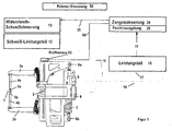
- FIG. 1 shows a welding gun for connecting sheet metal parts 1 with two pivotable about a common pivot point 2 electrode arms 3 a, b.
- pin electrodes 4a, b are arranged, which are the end face at the contact point with the sheet metal parts 1 surrounded by electrode caps 5a, 5b.
- electrode caps 5a, 5b At the opposite ends of the electrode arms 3a, 3b are inserted into Elektrodenarmhalterungen and clamped by means of screws.
- the distance between the electrodes 4 a, b can be changed with a driven by an electric motor 6, in particular a servomotor, spindle 7, in which it changes the distance between at the opposite ends of the electrode arms 3 a, b arranged joints 8 a, 8 b.
- the welding current flows from a welding transformer 9 through the electrode arms 3 a, b to the electrodes 4 a, b.
- the welding transformer 9 is connected via a welding power cable 11 to a welding power section 12 controlled by a resistance welding control 13.
- the force sensor 63 is first to be calibrated so that it supplies true actual force values between the electrodes, regardless of the location of its mounting. This is carried out in a manner known per se by means of a calibrated reference force sensor which directly detects the force between the electrodes 4a, 4b.
- a calibrated reference force sensor which directly detects the force between the electrodes 4a, 4b.
- the force sensor 63 is a in the FIG. 1 integrated electric charge amplifier, which represents the change of the electric charge into a voltage signal, the force actual value 60 (FIG. FIG. 1 ), and transmits via a measuring cable to a clamp controller 24.
- the electric motor 6 for the movement of the electrode arms 3a, 3b is via a motor cable 14 with a commercial power unit 15 connected for the drive of welding guns.
- the power unit is connected in a conventional manner with a pliers control 24 with integrated position control 25.
- the forceps and resistance welding controls (24, 13) are preceded by a robot controller (50).
- the signals between the robot controller (50) on the one hand and the clamp controller (24) and resistance welding controller (13) on the other hand are transmitted via an interface.
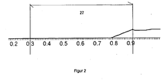
- the sequence for setting a welding point with the welding gun described is divided into a closing phase 27 (cf. FIG. 2 ) and a welding phase 30.
- the welding phase 30 is subdivided into a pre-press time 87, the welding time 88 and the repressing time 89 (cf. Fig.3,4 ).
- the welding current flows only during the welding time 88, whereby the current flow can be interrupted during the welding time.
- the electrodes are pressed against the sheets to be welded without a welding current flowing.
- the different sections of the welding phase are in Figures 3 . 4 characterized by the vertical dashed lines 91 to 96.
- the pliers control is given a value for a desired force between the two electrodes 4a, 4b during the welding phase. This value depends on the welding task and is based on empirical values known to those skilled in the art.
- the electrodes touch the sheets to be welded after about 0.79 seconds like this FIG. 2 is apparent. Subsequently, the force builds up between the electrodes 4a, 4b, as can be seen from the increase in the actual force between the electrodes in the diagram in FIG. 2 is recognizable. At the latest from this time on the Force actual value 60 and the actual position value 17 continuously detected with high accuracy and stored in the clamp controller 24.
- the closing phase can also be used to determine the spring constant of the welding device and store it in the pliers control. This can save cycle time.
- the actual force 60 between the two electrodes 4a, b is increased.
- a first value of the actual force e.g. in the amount of 50% of the predetermined setpoint force, and the actual position value of the spindle associated with this first value of the actual force is detected and stored.
- at least one further actual value 17 of the spindle, which value is different from the first value, of the actual force between the electrodes and the position actual value 17 belonging to this further value is detected and stored.
- This actual force value 60 may correspond, for example, to the value of the predetermined desired force, but may also be a lesser value of, for example, 80% of the desired force.
- the two pairs of values from detected Istkraft and associated actual position value can also be determined by timing shortly after touching the electrodes with the sheets, for example after 0.85 sec a first pair of values is detected and a short time later, for example, after 0.9 sec (see Fig. 2 ) a second pair of values is detected.
- the spring constant of the welding gun is now determined from the two value pairs of the force actual values 60 and the associated actual position value 17.
- D stands for the spring constant
- x for the deformation path.
- the restoring force of the electrodes 4a, b goes out and therefore corresponds to the difference between the two measured Actual force values 60.
- the deformation path x is the difference between the two detected position actual values 17 on the spindle 7.
- the spring constant can be determined empirically.
- the gun controller 24 Upon reaching the desired force and after completion of the closing phase, the gun controller 24 transmits a start signal 35, such as an active 24 volt level, to the resistance welding controller 13, which triggers welding current for the welding operation after a programmed pre-press time 87.
- a start signal 35 such as an active 24 volt level
- the resistance welding control 13 generates a current flow between the two electrode caps 5a, 5b via the welding power part 12 and the welding transformer 9 through the sheet metal parts 1 therebetween.
- the two electrode caps 5a, 5b press the sheet metal parts 1 together, whereby the now soft and / or liquid material is first expanded and then deformed, compressed and / or pushed to the side, so that the two electrode caps 5a, 5b initially remove from each other and then approach ("penetration").
- This expansion or approach of the two electrode caps 5a, 5b causes a load or force relief of the electrode arms 3a, 3b and resulting in a change in the measured actual force value 60.
- the currently detected actual force values 60 between the two electrodes 4 a, b are compared with the value for the desired force from the caliper control 24.
- the pliers control taking into account the previously determined spring constant from deviations between the continuously detected values for the actual force to the value for the desired force, calculates a value for a changed position of the spindle 7 to readjust the value of the actual force 60 to the value of the desired force as a reference variable.
- This regulation ensures that the deviation of the force actual value 60 between the electrodes is continuously minimized to the force setpoint specified for the respective welding. This results in an approximately constant force between the electrodes during the welding phase (30).
- the calculated values of the changed position serve as a reference variable of the position control 25 for the actual position values 17 to be controlled on the spindle 7.
- the calculated values of the changed positions can also be evaluated.
- the position actual values 17 can be detected with a very high resolution. Due to the constant readjustment of the actual force to the desired target value of the force between the electrodes as a reference variable, ie by keeping constant of the sensor signal of the force sensor 63, the changes in the electrode distances are reflected in the changes in the spindle position, be it the actual position value or the calculated values. Since the movements of the electrodes allow statements about the quality of the welded connection, such as the penetration of the electrodes, reliable evaluations of the quality of the weld can be made by evaluating the spindle position during the welding phase.
- the post-press time 89 (between lines 95 and 96) of the welding phase is included in the evaluation.
- a reference range 44 of the detected actual position values within the welding phase is determined.
- the reference region 44 extends over the entire pre-press time and about 1/3 of the welding time (up to the line 93).
- a rear measuring range 45 is established (between the lines 94 and 96), which begins, for example, shortly before the end of the welding time 88 and ends with the end of the repressing time.
- the evaluation of the position values and the actual forces during the welding phase 30 also allows the detection of an air gap, splashes and shunt.
- FIG. 4 clarifies how from the position values during the welding phase, a SLE measure for the weld nugget 83 is calculated and compared with a limit value. If, in addition to a sufficient penetration of the electrodes, the weld nugget heating also lies in a defined range, the presence of a proper weld can be recognized with even greater accuracy.
- the welding lens heating is accompanied by a short-term increase in distance between the electrodes 4a, b.
- the change in the actual force value 60 involves a change in position during the welding phase in order to readjust the actual force value to the value of the predetermined desired force. Consequently, a correct weld nugget warming will show as a characteristic rash in the curve of position values in the second half of the weld time. A comparable-looking rash in the first half of the welding time is not included in the evaluation.
- a linear regression between the position values and the time is calculated at least in the second half of the welding time.
- the linear regression was calculated starting from the end of the welding time until the completion of the welding time 88.
- the time limits for the calculation of the regression line 82 are in FIG. 4 indicated by dashed lines 93 and 95.
- the SLE metric is defined as the area 83 between the regression line and the characteristic deflection of the position value curve 17. The characteristic deflection of the curve may vary depending on the welding task and must be determined empirically for the particular welding task.
- the shape of the characteristic rash has been determined, it is found within the scope of the evaluation of the position values according to the invention by means of per se known pattern recognition methods for each welding within the second half of the welding time and the SLE measurement is determined. If the SLE measurement is within certain limits, it can be concluded that there is sufficient weld nugget heating.
- the slope 84 of the regression line after FIG. 4 and the coefficient of determination 85 calculated from the linear regression can also be included in the evaluation.
- Certain combinations of the penetration depth 51, the SLE measure 83 and the slope 84 as well as the coefficient of determination 85 of the regression line 82 to be empirically determined for the respective welding task allow conclusions to be drawn about an air gap or a shunt that exists.
- the method described by way of example uses the method of linear regression partly for the evaluation of the measured values. This algorithm is characterized by short computing times. In addition, however, other regression methods can be used without departing from the inventive method.
- the recorded force curve can be examined to detect spatter formation during welding (cf. FIG. 5 ).
- a regression curve of the force actual values 60 is first calculated at least over the second half of the welding time.
- a characteristic of the actual force values characteristic of a spatter formation is searched for over the welding time using per se known pattern recognition methods within the second half of the welding time 88. In FIG. 5 such a form exists.
- the area 81 between the regression curve and the curve defined by the force actual values 60 is determined. The determined area serves as a measure, which is compared with at least one limit.
Landscapes
- Engineering & Computer Science (AREA)
- Mechanical Engineering (AREA)
- Quality & Reliability (AREA)
- Resistance Welding (AREA)
- Investigating Or Analyzing Materials By The Use Of Electric Means (AREA)
- Numerical Control (AREA)
Claims (10)
- Procédé de soudage électrique par résistance, ainsi que d'évaluation de la qualité d'un assemblage par soudure d'au moins deux pièces en tôle (1) au moyen d'un dispositif de soudage, avec des électrodes (4a, 4b) mobiles l'une vers l'autre, une broche à entraînement électrique pour déplacer au moins l'une des deux électrodes, avec des moyens pour générer le courant de soudage et avec un capteur de force (63) disposé sur la pince porte-électrodes pour détecter une valeur réelle de force entre les deux électrodes, une commande pour le dispositif de soudage, ainsi qu'un réglage de position (25) pour la broche (6) à entraînement électrique, la constante de rappel du dispositif de soudage étant déterminée et mémorisée dans la commande (24), caractérisé en ce que- il est prédéfini pour la commande (24) une valeur pour une force de consigne entre les deux électrodes pendant la phase de soudage (30),- les valeurs détectées pour la force réelle (60) entre les deux électrodes (4) sont comparées en permanence avec la valeur pour la force de consigne par la commande (24)- en tenant compte de la constante de rappel, la commande (24) calcule à partir d'écarts entre les valeurs détectées en permanence pour la force réelle (60) et la valeur pour la force de consigne une valeur pour une position modifiée de la broche, pour réajuster la valeur de la force réelle à la valeur de la force de consigne en tant que grandeur de référence,- les valeurs calculées pour la position modifiée en tant que grandeur de référence du réglage de position (25) servent pour les valeurs réelles de position à régler sur la broche,- et les valeurs calculées pour la position modifiée ou les valeurs réelles de position (17), ci-dessous appelées valeurs de position, sont interprétées pour l'estimation de la qualité de l'assemblage par soudure.
- Procédé selon la revendication 1, caractérisé en ce que- la constante de rappel du dispositif de soudage est déterminée, en ce qu'après la fermeture des deux électrodes, mais avant le début de la phase de soudage, la force réelle est augmentée entre les électrodes,- une première valeur est détectée pour la force réelle entre les électrodes et la valeur réelle de position de la broche correspondant à ladite première valeur,- en ce qu'ensuite au moins une valeur supplémentaire pour la force réelle, différente de la première valeur est détectée entre les électrodes et en ce que la valeur réelle de position de la broche correspondant à ladite valeur supplémentaire est détectée et,- à partir des au moins deux paires de valeurs de la force réelle et de la valeur réelle de position, la constante de rappel est déterminée et mémorisée dans la commande de la pince, au moins jusqu'à une nouvelle détermination des constantes de rappel du dispositif de soudage.
- Procédé selon la revendication 2, caractérisé en ce que la constante de rappel est déterminée avant chaque phase de soudage (30).
- Procédé selon l'une quelconque des revendications 1 à 3, caractérisé en ce que,- une plage de référence (44) est fixée dans la phase de soudage (30) pour les valeurs réelles de position (17) détectées, laquelle commence pendant le temps de précompression (87) de la phase de soudage et dure au maximum jusqu'à la fusion des tôles à souder,- une plage de mesure (45) successive à la plage de référence (44) est fixée, laquelle commence notamment avant l'achèvement du temps de soudage (88) et prend fin avec l'écoulement du temps de post-compression (89) et- par une comparaison des valeurs de position (17) de la plage de référence (44) et de la plage de mesure (45), avec au moins une valeur limite mémorisée dans la commande (24), il est déterminé une profondeur de pénétration suffisante des électrodes pendant la phase de soudage (30).
- Procédé selon la revendication 4, caractérisé en ce que - pour la plage de référence (44) et la plage de mesure (45), il est calculé une régression linéaire entre les valeurs de position (17) et le temps, dont il résulte chaque fois une droite (46, 47) pour la plage de référence (44) et la plage de mesure (45),- en ce que les barycentres (48, 49) définis par le centre des droites (46, 47) sont déterminés pour la plage de référence (44) et la plage de mesure (45) et en ce qu'à partir de la différence entre les barycentres, il est calculé une cote dimensionnelle, qui est comparée avec au mois une valeur limite.
- Procédé selon l'une quelconque des revendications 1 à 5, caractérisé en ce que- une courbe de régression des valeurs de position (17) est d'abord calculée au moins sur la deuxième moitié du temps de soudage (88),- il est cherché au moins dans la deuxième moitié du temps de soudage (88) une extension des valeurs de position (17) sur le temps de soudage, caractéristique de l'échauffement du noyau de soudure (83) avec des procédés de reconnaissance des formes connus en soi (88)- s'il est trouvé une extension caractéristique, la surface entre à courbe de régression (82) et le trajet de la courbe défini par les valeurs de position (17) est déterminé dans la plage de l'extension caractéristique, la surface servant de cote dimensionnelle pour l'échauffement du noyau de soudure (83) - et pour l'évaluation de l'échauffement du noyau de soudure (83), cette cote dimensionnelle est comparée avec au moins une valeur limite.
- Procédé selon l'une quelconque des revendications 1 à 6, caractérisé en ce qu'il est calculé d'abord une droite de régression linéaire (82) des valeurs de position (17) au moins sur la deuxième moitié du temps de soudage (88) et la cote de précision (85) calculée à partir de la régression linéaire est co-impliquée dans l'évaluation.
- Procédé selon l'une quelconque des revendications 1 à 7, caractérisé en ce que,- une courbe de régression des valeurs réelles de force est d'abord calculée au moins sur la deuxième moitié du temps de soudage (88),- il est cherché au moins dans la deuxième moitié du temps de soudage (88) une extension des valeurs réelles de force, caractéristique d'une formation de projections sur le temps de soudage avec des procédés de reconnaissance des formes connus en soi,- et s'il est trouvé une extension caractéristique, la surface (81) entre la courbe de régression et le trajet de la courbe défini par les valeurs réelles de position (60) est déterminé dans la plage de l'extension caractéristique, la surface (81) servant de cote dimensionnelle pour la formation de projections- et pour l'évaluation de la formation de projections, cette cote dimensionnelle est comparée avec au moins une valeur limite.
- Dispositif de soudage avec au moins deux électrodes (4a, 4b) mobiles l'une vers l'autre, une broche à entraînement électrique pour déplacer au moins l'une des deux électrodes, avec des moyens pour générer le courant de soudage, un capteur de force (63) disposé sur la pince porte-électrodes pour détecter une valeur réelle de force entre les deux électrodes, ainsi qu'un réglage de position (25) pour la broche (6) à entraînement électrique, ainsi qu'une commande (24), qui est conçue pour la mise en oeuvre des étapes suivantes :- la constante de rappel du dispositif de soudage est mémorisée dans la commande (24)- la commande compare en permanence les valeurs détectées de la force réelle (60) entre les deux électrodes (4) avec la valeur pour la force de consigne, une valeur étant prescrite par la commande (24) pour la force de consigne entre les deux électrodes pendant la phase de soudage (30),- en tenant compte de la constante de rappel, la commande (24) calcule à partir d'écarts entre les valeurs détectées en permanence pour la force réelle (60) et la valeur pour la force de consigne une valeur pour une position modifiée de la broche, pour réajuster la valeur de la force réelle à la valeur de la force de consigne en tant que grandeur de référence, les valeurs calculées pour la position modifiée servant de grandeur de référence du réglage de position (25) pour les valeurs réelles de position à régler sur la broche- et les valeurs calculées pour la position modifiée ou les valeurs de position réelle (17), ci-dessous appelées valeurs de position, sont mémorisées dans la commande et interprétées pour l'estimation de la qualité de l'assemblage par soudure.
- Dispositif de soudage selon la revendication 9, caractérisé en ce qu'il s'agit d'une pince porte-électrodes ou d'une presse à souder.
Applications Claiming Priority (2)
| Application Number | Priority Date | Filing Date | Title |
|---|---|---|---|
| DE102004015704 | 2004-03-29 | ||
| DE102004015704A DE102004015704B3 (de) | 2004-03-29 | 2004-03-29 | Verfahren zum elektrischen Widerstandsschweißen sowie zur Beurteilung der Qualität einer Schweißverbindung |
Publications (3)
| Publication Number | Publication Date |
|---|---|
| EP1582285A2 EP1582285A2 (fr) | 2005-10-05 |
| EP1582285A3 EP1582285A3 (fr) | 2006-03-15 |
| EP1582285B1 true EP1582285B1 (fr) | 2008-09-24 |
Family
ID=34877662
Family Applications (1)
| Application Number | Title | Priority Date | Filing Date |
|---|---|---|---|
| EP05004398A Expired - Lifetime EP1582285B1 (fr) | 2004-03-29 | 2005-03-01 | Méthode de soudage par résistance et d'évalution de la qualité d'une soudure |
Country Status (4)
| Country | Link |
|---|---|
| EP (1) | EP1582285B1 (fr) |
| AT (1) | ATE409094T1 (fr) |
| DE (2) | DE102004015704B3 (fr) |
| ES (1) | ES2314503T3 (fr) |
Families Citing this family (6)
| Publication number | Priority date | Publication date | Assignee | Title |
|---|---|---|---|---|
| DE102011003539A1 (de) | 2011-02-02 | 2012-08-02 | Kuka Roboter Gmbh | Verfahren zum Referenzieren einer Antriebsstellung wenigstens eines elektrischen Antriebs |
| JP5638102B2 (ja) | 2013-03-28 | 2014-12-10 | ファナック株式会社 | スポット溶接ガンを有するスポット溶接システム |
| DE102014226655A1 (de) * | 2014-12-19 | 2016-06-23 | Kuka Roboter Gmbh | Verfahren und System zum Kalibrieren der Zangenpresskraft einer automatischen ansteuerbaren Fertigungszange |
| DE102015114957A1 (de) | 2015-09-07 | 2017-03-09 | Harms + Wende Gmbh & Co. Kg | Elektrisches Schweißverfahren |
| DE102018105893B4 (de) * | 2018-03-14 | 2022-02-10 | GLAMAtronic Schweiß- und Anlagentechnik GmbH | Verfahren und Vorrichtung zum Qualitätsauswerten beim Widerstandsschweißen sowie Computerprogrammprodukt, Steuerungseinrichtung und Verwendung |
| DE102020200616A1 (de) * | 2020-01-21 | 2021-07-22 | Robert Bosch Gesellschaft mit beschränkter Haftung | Vorrichtung für eine schweisssteuerung und verfahren zur plausibilisierung von kraftwerten bei der steuerung eines schweisswerkzeugs |
Family Cites Families (4)
| Publication number | Priority date | Publication date | Assignee | Title |
|---|---|---|---|---|
| FR2631866A1 (fr) * | 1988-05-25 | 1989-12-01 | Peugeot | Procede de soudage par resistance et dispositif pour sa mise en oeuvre |
| DE4332807C2 (de) * | 1992-10-20 | 2002-07-18 | Schlattl Werner Bavaria Tech | Opto-elektrischer Sensor |
| JP3593981B2 (ja) * | 2000-01-20 | 2004-11-24 | 日産自動車株式会社 | 溶接電極間移動量検出方法および装置 |
| EP1291113A1 (fr) * | 2001-09-11 | 2003-03-12 | Cosytronic Computer-System-Electronic GmbH | Pistolet de soudage et méthode de déterminer la qualité d'une soudure |
-
2004
- 2004-03-29 DE DE102004015704A patent/DE102004015704B3/de not_active Expired - Fee Related
-
2005
- 2005-03-01 ES ES05004398T patent/ES2314503T3/es not_active Expired - Lifetime
- 2005-03-01 EP EP05004398A patent/EP1582285B1/fr not_active Expired - Lifetime
- 2005-03-01 AT AT05004398T patent/ATE409094T1/de not_active IP Right Cessation
- 2005-03-01 DE DE502005005442T patent/DE502005005442D1/de not_active Expired - Lifetime
Also Published As
| Publication number | Publication date |
|---|---|
| DE102004015704B3 (de) | 2005-10-20 |
| EP1582285A3 (fr) | 2006-03-15 |
| ES2314503T3 (es) | 2009-03-16 |
| ATE409094T1 (de) | 2008-10-15 |
| EP1582285A2 (fr) | 2005-10-05 |
| DE502005005442D1 (de) | 2008-11-06 |
Similar Documents
| Publication | Publication Date | Title |
|---|---|---|
| DE19917896B4 (de) | Punktschweißverfahren | |
| EP1409190B1 (fr) | Dispositif de soudage par resistance et procede de commande associe | |
| DE102016107398B4 (de) | Qualitätskontrollsystem für punktschweissen | |
| DE102011009379B4 (de) | Punktschweisssystem und Positionserkennungsverfahren für ein zu schweißendes Werkstück | |
| EP0960017B1 (fr) | Procede pour faire fonctionner une presse electrique | |
| WO2019002141A1 (fr) | Procédé et dispositif servant à balayer une surface de pièce d'une pièce métallique | |
| DE4306492C1 (de) | Schweißzangenregelung | |
| EP2714323B1 (fr) | Procédé et dispositif destinés à l'assemblage de pièces par soudage par faisceau d'énergie | |
| EP1582285B1 (fr) | Méthode de soudage par résistance et d'évalution de la qualité d'une soudure | |
| EP3122483A1 (fr) | Procédé permettant de positionner un galet de dressage d'une installation de dressage à galets | |
| DE102008028385B4 (de) | Mess- und Steuerverfahren zum Widerstandsschweißen | |
| WO1997015415A2 (fr) | Procede de commande d'un dispositif de soudage et dispositif de soudage correspondant | |
| DE10144286C1 (de) | Verfahren zur Beurteilung der Qualität einer Schweißverbindung | |
| DE10144731B4 (de) | Schweißzange sowie Verfahren zum Widerstandsschweißen mit Beurteilung der Qualität einer Schweißverbindung | |
| EP3138652B1 (fr) | Procédé de soudure électrique | |
| DE102008005113B4 (de) | Verfahren zur Sicherung der Schweißqualität von Schweißpunkten beim Widerstandspunktschweißen einer bestimmten Materialkombination | |
| WO2022078901A1 (fr) | Procédé de surveillance et de modification de la position d'au moins une barre de roulement d'une presse métallique, et presse métallique | |
| WO2003072278A1 (fr) | Procede de reduction des erreurs d'angle de pliage lors du pliage | |
| EP1582286B1 (fr) | Méthode d'amélioration de la qualité d'une soudure par point | |
| EP1291113A1 (fr) | Pistolet de soudage et méthode de déterminer la qualité d'une soudure | |
| EP1661638A2 (fr) | Procédé et laminoir pour le laminage de précision des pièces à symétrie de rotation | |
| EP3124160B1 (fr) | Procede adaptatif destine au fraisage des electrodes de dispositifs de soudage par points | |
| DE102013217584A1 (de) | Erkennen von Schweißspritzern durch Elektrodenkraftüberwachung | |
| DE10258059B4 (de) | Verfahren zum Steuern einer Werkzeug-Anpreßkraft bei Fügevorrichtungen | |
| EP2105237A2 (fr) | Procédé destiné à la commande d'une force de pression à électrodes pour une pince à souder tout comme pince à souder correspondante |
Legal Events
| Date | Code | Title | Description |
|---|---|---|---|
| PUAI | Public reference made under article 153(3) epc to a published international application that has entered the european phase |
Free format text: ORIGINAL CODE: 0009012 |
|
| AK | Designated contracting states |
Kind code of ref document: A2 Designated state(s): AT BE BG CH CY CZ DE DK EE ES FI FR GB GR HU IE IS IT LI LT LU MC NL PL PT RO SE SI SK TR |
|
| AX | Request for extension of the european patent |
Extension state: AL BA HR LV MK YU |
|
| PUAL | Search report despatched |
Free format text: ORIGINAL CODE: 0009013 |
|
| AK | Designated contracting states |
Kind code of ref document: A3 Designated state(s): AT BE BG CH CY CZ DE DK EE ES FI FR GB GR HU IE IS IT LI LT LU MC NL PL PT RO SE SI SK TR |
|
| AX | Request for extension of the european patent |
Extension state: AL BA HR LV MK YU |
|
| 17P | Request for examination filed |
Effective date: 20060626 |
|
| 17Q | First examination report despatched |
Effective date: 20060929 |
|
| REG | Reference to a national code |
Ref country code: HK Ref legal event code: DE Ref document number: 1088659 Country of ref document: HK |
|
| AKX | Designation fees paid |
Designated state(s): AT BE BG CH CY CZ DE DK EE ES FI FR GB GR HU IE IS IT LI LT LU MC NL PL PT RO SE SI SK TR |
|
| GRAP | Despatch of communication of intention to grant a patent |
Free format text: ORIGINAL CODE: EPIDOSNIGR1 |
|
| GRAS | Grant fee paid |
Free format text: ORIGINAL CODE: EPIDOSNIGR3 |
|
| GRAA | (expected) grant |
Free format text: ORIGINAL CODE: 0009210 |
|
| AK | Designated contracting states |
Kind code of ref document: B1 Designated state(s): AT BE BG CH CY CZ DE DK EE ES FI FR GB GR HU IE IS IT LI LT LU MC NL PL PT RO SE SI SK TR |
|
| REG | Reference to a national code |
Ref country code: GB Ref legal event code: FG4D Free format text: NOT ENGLISH |
|
| REG | Reference to a national code |
Ref country code: CH Ref legal event code: EP |
|
| REG | Reference to a national code |
Ref country code: IE Ref legal event code: FG4D Free format text: LANGUAGE OF EP DOCUMENT: GERMAN |
|
| REF | Corresponds to: |
Ref document number: 502005005442 Country of ref document: DE Date of ref document: 20081106 Kind code of ref document: P |
|
| PG25 | Lapsed in a contracting state [announced via postgrant information from national office to epo] |
Ref country code: LT Free format text: LAPSE BECAUSE OF FAILURE TO SUBMIT A TRANSLATION OF THE DESCRIPTION OR TO PAY THE FEE WITHIN THE PRESCRIBED TIME-LIMIT Effective date: 20080924 |
|
| PG25 | Lapsed in a contracting state [announced via postgrant information from national office to epo] |
Ref country code: SI Free format text: LAPSE BECAUSE OF FAILURE TO SUBMIT A TRANSLATION OF THE DESCRIPTION OR TO PAY THE FEE WITHIN THE PRESCRIBED TIME-LIMIT Effective date: 20080924 Ref country code: FI Free format text: LAPSE BECAUSE OF FAILURE TO SUBMIT A TRANSLATION OF THE DESCRIPTION OR TO PAY THE FEE WITHIN THE PRESCRIBED TIME-LIMIT Effective date: 20080924 |
|
| NLV1 | Nl: lapsed or annulled due to failure to fulfill the requirements of art. 29p and 29m of the patents act | ||
| REG | Reference to a national code |
Ref country code: ES Ref legal event code: FG2A Ref document number: 2314503 Country of ref document: ES Kind code of ref document: T3 |
|
| REG | Reference to a national code |
Ref country code: IE Ref legal event code: FD4D |
|
| PG25 | Lapsed in a contracting state [announced via postgrant information from national office to epo] |
Ref country code: BG Free format text: LAPSE BECAUSE OF FAILURE TO SUBMIT A TRANSLATION OF THE DESCRIPTION OR TO PAY THE FEE WITHIN THE PRESCRIBED TIME-LIMIT Effective date: 20081224 |
|
| PG25 | Lapsed in a contracting state [announced via postgrant information from national office to epo] |
Ref country code: SK Free format text: LAPSE BECAUSE OF FAILURE TO SUBMIT A TRANSLATION OF THE DESCRIPTION OR TO PAY THE FEE WITHIN THE PRESCRIBED TIME-LIMIT Effective date: 20080924 Ref country code: PT Free format text: LAPSE BECAUSE OF FAILURE TO SUBMIT A TRANSLATION OF THE DESCRIPTION OR TO PAY THE FEE WITHIN THE PRESCRIBED TIME-LIMIT Effective date: 20090224 Ref country code: RO Free format text: LAPSE BECAUSE OF FAILURE TO SUBMIT A TRANSLATION OF THE DESCRIPTION OR TO PAY THE FEE WITHIN THE PRESCRIBED TIME-LIMIT Effective date: 20080924 Ref country code: CZ Free format text: LAPSE BECAUSE OF FAILURE TO SUBMIT A TRANSLATION OF THE DESCRIPTION OR TO PAY THE FEE WITHIN THE PRESCRIBED TIME-LIMIT Effective date: 20080924 Ref country code: IS Free format text: LAPSE BECAUSE OF FAILURE TO SUBMIT A TRANSLATION OF THE DESCRIPTION OR TO PAY THE FEE WITHIN THE PRESCRIBED TIME-LIMIT Effective date: 20090124 Ref country code: NL Free format text: LAPSE BECAUSE OF FAILURE TO SUBMIT A TRANSLATION OF THE DESCRIPTION OR TO PAY THE FEE WITHIN THE PRESCRIBED TIME-LIMIT Effective date: 20080924 |
|
| PG25 | Lapsed in a contracting state [announced via postgrant information from national office to epo] |
Ref country code: EE Free format text: LAPSE BECAUSE OF FAILURE TO SUBMIT A TRANSLATION OF THE DESCRIPTION OR TO PAY THE FEE WITHIN THE PRESCRIBED TIME-LIMIT Effective date: 20080924 Ref country code: IE Free format text: LAPSE BECAUSE OF FAILURE TO SUBMIT A TRANSLATION OF THE DESCRIPTION OR TO PAY THE FEE WITHIN THE PRESCRIBED TIME-LIMIT Effective date: 20080924 Ref country code: DK Free format text: LAPSE BECAUSE OF FAILURE TO SUBMIT A TRANSLATION OF THE DESCRIPTION OR TO PAY THE FEE WITHIN THE PRESCRIBED TIME-LIMIT Effective date: 20080924 |
|
| PLBE | No opposition filed within time limit |
Free format text: ORIGINAL CODE: 0009261 |
|
| STAA | Information on the status of an ep patent application or granted ep patent |
Free format text: STATUS: NO OPPOSITION FILED WITHIN TIME LIMIT |
|
| REG | Reference to a national code |
Ref country code: GB Ref legal event code: 732E Free format text: REGISTERED BETWEEN 20090709 AND 20090715 |
|
| PG25 | Lapsed in a contracting state [announced via postgrant information from national office to epo] |
Ref country code: IT Free format text: LAPSE BECAUSE OF FAILURE TO SUBMIT A TRANSLATION OF THE DESCRIPTION OR TO PAY THE FEE WITHIN THE PRESCRIBED TIME-LIMIT Effective date: 20080924 |
|
| 26N | No opposition filed |
Effective date: 20090625 |
|
| BERE | Be: lapsed |
Owner name: COSYTRONIC COMPUTER-SYSTEM-ELECTRONIC G.M.B.H. Effective date: 20090331 Owner name: MICOM TECHNOLOGIE G.- FUR AUTOMATION MBH & CO. KG Effective date: 20090331 |
|
| PG25 | Lapsed in a contracting state [announced via postgrant information from national office to epo] |
Ref country code: MC Free format text: LAPSE BECAUSE OF NON-PAYMENT OF DUE FEES Effective date: 20090331 |
|
| REG | Reference to a national code |
Ref country code: CH Ref legal event code: PL |
|
| REG | Reference to a national code |
Ref country code: ES Ref legal event code: PC2A |
|
| REG | Reference to a national code |
Ref country code: FR Ref legal event code: ST Effective date: 20091130 |
|
| PG25 | Lapsed in a contracting state [announced via postgrant information from national office to epo] |
Ref country code: LI Free format text: LAPSE BECAUSE OF NON-PAYMENT OF DUE FEES Effective date: 20090331 Ref country code: SE Free format text: LAPSE BECAUSE OF FAILURE TO SUBMIT A TRANSLATION OF THE DESCRIPTION OR TO PAY THE FEE WITHIN THE PRESCRIBED TIME-LIMIT Effective date: 20081224 Ref country code: CH Free format text: LAPSE BECAUSE OF NON-PAYMENT OF DUE FEES Effective date: 20090331 |
|
| PG25 | Lapsed in a contracting state [announced via postgrant information from national office to epo] |
Ref country code: BE Free format text: LAPSE BECAUSE OF NON-PAYMENT OF DUE FEES Effective date: 20090331 |
|
| PG25 | Lapsed in a contracting state [announced via postgrant information from national office to epo] |
Ref country code: FR Free format text: LAPSE BECAUSE OF NON-PAYMENT OF DUE FEES Effective date: 20091123 |
|
| PG25 | Lapsed in a contracting state [announced via postgrant information from national office to epo] |
Ref country code: PL Free format text: LAPSE BECAUSE OF FAILURE TO SUBMIT A TRANSLATION OF THE DESCRIPTION OR TO PAY THE FEE WITHIN THE PRESCRIBED TIME-LIMIT Effective date: 20080924 |
|
| PG25 | Lapsed in a contracting state [announced via postgrant information from national office to epo] |
Ref country code: AT Free format text: LAPSE BECAUSE OF NON-PAYMENT OF DUE FEES Effective date: 20090301 |
|
| PG25 | Lapsed in a contracting state [announced via postgrant information from national office to epo] |
Ref country code: GR Free format text: LAPSE BECAUSE OF FAILURE TO SUBMIT A TRANSLATION OF THE DESCRIPTION OR TO PAY THE FEE WITHIN THE PRESCRIBED TIME-LIMIT Effective date: 20081225 |
|
| REG | Reference to a national code |
Ref country code: GB Ref legal event code: 732E Free format text: REGISTERED BETWEEN 20110106 AND 20110112 |
|
| PG25 | Lapsed in a contracting state [announced via postgrant information from national office to epo] |
Ref country code: LU Free format text: LAPSE BECAUSE OF NON-PAYMENT OF DUE FEES Effective date: 20090301 |
|
| REG | Reference to a national code |
Ref country code: DE Ref legal event code: R081 Ref document number: 502005005442 Country of ref document: DE Owner name: IPG PHOTONICS CORP., US Free format text: FORMER OWNER: COSYTRONIC,COMPUTER-SYSTEM-ELEC, MICOM TECHNOLOGIE GESELLSCHAFT, , DE Effective date: 20110304 Ref country code: DE Ref legal event code: R081 Ref document number: 502005005442 Country of ref document: DE Owner name: MICOM TECHNOLOGIE GESELLSCHAFT FUER AUTOMATION, DE Free format text: FORMER OWNER: COSYTRONIC,COMPUTER-SYSTEM-ELEC, MICOM TECHNOLOGIE GESELLSCHAFT, , DE Effective date: 20110304 Ref country code: DE Ref legal event code: R081 Ref document number: 502005005442 Country of ref document: DE Owner name: MICOM TECHNOLOGIE GESELLSCHAFT FUER AUTOMATION, DE Free format text: FORMER OWNERS: COSYTRONIC,COMPUTER-SYSTEM-ELECTRONIC KG, 57537 WISSEN, DE; MICOM TECHNOLOGIE GESELLSCHAFT FUER AUTOMATION MBH & CO. KG, 52076 AACHEN, DE Effective date: 20110304 Ref country code: DE Ref legal event code: R081 Ref document number: 502005005442 Country of ref document: DE Owner name: IPG PHOTONICS CORP., OXFORD, US Free format text: FORMER OWNERS: COSYTRONIC,COMPUTER-SYSTEM-ELECTRONIC KG, 57537 WISSEN, DE; MICOM TECHNOLOGIE GESELLSCHAFT FUER AUTOMATION MBH & CO. KG, 52076 AACHEN, DE Effective date: 20110304 |
|
| PG25 | Lapsed in a contracting state [announced via postgrant information from national office to epo] |
Ref country code: HU Free format text: LAPSE BECAUSE OF FAILURE TO SUBMIT A TRANSLATION OF THE DESCRIPTION OR TO PAY THE FEE WITHIN THE PRESCRIBED TIME-LIMIT Effective date: 20090325 |
|
| PG25 | Lapsed in a contracting state [announced via postgrant information from national office to epo] |
Ref country code: TR Free format text: LAPSE BECAUSE OF FAILURE TO SUBMIT A TRANSLATION OF THE DESCRIPTION OR TO PAY THE FEE WITHIN THE PRESCRIBED TIME-LIMIT Effective date: 20080924 |
|
| PG25 | Lapsed in a contracting state [announced via postgrant information from national office to epo] |
Ref country code: CY Free format text: LAPSE BECAUSE OF FAILURE TO SUBMIT A TRANSLATION OF THE DESCRIPTION OR TO PAY THE FEE WITHIN THE PRESCRIBED TIME-LIMIT Effective date: 20080924 |
|
| REG | Reference to a national code |
Ref country code: HK Ref legal event code: WD Ref document number: 1088659 Country of ref document: HK |
|
| PGFP | Annual fee paid to national office [announced via postgrant information from national office to epo] |
Ref country code: DE Payment date: 20150211 Year of fee payment: 11 Ref country code: ES Payment date: 20150325 Year of fee payment: 11 |
|
| PGFP | Annual fee paid to national office [announced via postgrant information from national office to epo] |
Ref country code: GB Payment date: 20150324 Year of fee payment: 11 |
|
| REG | Reference to a national code |
Ref country code: DE Ref legal event code: R119 Ref document number: 502005005442 Country of ref document: DE |
|
| GBPC | Gb: european patent ceased through non-payment of renewal fee |
Effective date: 20160301 |
|
| PG25 | Lapsed in a contracting state [announced via postgrant information from national office to epo] |
Ref country code: GB Free format text: LAPSE BECAUSE OF NON-PAYMENT OF DUE FEES Effective date: 20160301 Ref country code: DE Free format text: LAPSE BECAUSE OF NON-PAYMENT OF DUE FEES Effective date: 20161001 |
|
| REG | Reference to a national code |
Ref country code: ES Ref legal event code: FD2A Effective date: 20170428 |
|
| PG25 | Lapsed in a contracting state [announced via postgrant information from national office to epo] |
Ref country code: ES Free format text: LAPSE BECAUSE OF NON-PAYMENT OF DUE FEES Effective date: 20160302 |