EP1582386A2 - Fensterrollo für Kraftfahrzeuge - Google Patents
Fensterrollo für Kraftfahrzeuge Download PDFInfo
- Publication number
- EP1582386A2 EP1582386A2 EP05007288A EP05007288A EP1582386A2 EP 1582386 A2 EP1582386 A2 EP 1582386A2 EP 05007288 A EP05007288 A EP 05007288A EP 05007288 A EP05007288 A EP 05007288A EP 1582386 A2 EP1582386 A2 EP 1582386A2
- Authority
- EP
- European Patent Office
- Prior art keywords
- roller blind
- guide
- window
- blind according
- winding
- Prior art date
- Legal status (The legal status is an assumption and is not a legal conclusion. Google has not performed a legal analysis and makes no representation as to the accuracy of the status listed.)
- Granted
Links
- 238000004804 winding Methods 0.000 claims description 40
- 239000000463 material Substances 0.000 claims description 17
- 239000004033 plastic Substances 0.000 claims description 8
- 229920003023 plastic Polymers 0.000 claims description 8
- 239000004753 textile Substances 0.000 claims description 6
- 230000001154 acute effect Effects 0.000 claims description 4
- 229910052751 metal Inorganic materials 0.000 claims description 4
- 239000002184 metal Substances 0.000 claims description 4
- 239000004809 Teflon Substances 0.000 claims description 3
- 229920006362 Teflon® Polymers 0.000 claims description 3
- 238000004026 adhesive bonding Methods 0.000 claims description 3
- 230000015572 biosynthetic process Effects 0.000 claims description 3
- 229920002430 Fibre-reinforced plastic Polymers 0.000 claims description 2
- 239000002131 composite material Substances 0.000 claims description 2
- 239000004744 fabric Substances 0.000 claims description 2
- 239000011151 fibre-reinforced plastic Substances 0.000 claims description 2
- 239000000203 mixture Substances 0.000 claims description 2
- 239000002985 plastic film Substances 0.000 claims description 2
- 238000009958 sewing Methods 0.000 claims description 2
- 238000002604 ultrasonography Methods 0.000 claims description 2
- 238000003466 welding Methods 0.000 claims description 2
- 238000009434 installation Methods 0.000 description 6
- 230000006978 adaptation Effects 0.000 description 4
- 238000013461 design Methods 0.000 description 3
- 238000004146 energy storage Methods 0.000 description 3
- 238000010438 heat treatment Methods 0.000 description 3
- 238000010521 absorption reaction Methods 0.000 description 2
- 229910052782 aluminium Inorganic materials 0.000 description 2
- XAGFODPZIPBFFR-UHFFFAOYSA-N aluminium Chemical compound [Al] XAGFODPZIPBFFR-UHFFFAOYSA-N 0.000 description 2
- 230000037237 body shape Effects 0.000 description 2
- 230000006835 compression Effects 0.000 description 2
- 238000007906 compression Methods 0.000 description 2
- 238000011161 development Methods 0.000 description 2
- 230000018109 developmental process Effects 0.000 description 2
- 238000000034 method Methods 0.000 description 2
- 239000005060 rubber Substances 0.000 description 2
- 239000000654 additive Substances 0.000 description 1
- 238000004378 air conditioning Methods 0.000 description 1
- 238000013459 approach Methods 0.000 description 1
- 238000005452 bending Methods 0.000 description 1
- 238000010276 construction Methods 0.000 description 1
- 230000000694 effects Effects 0.000 description 1
- 238000005265 energy consumption Methods 0.000 description 1
- 230000010354 integration Effects 0.000 description 1
- 230000001788 irregular Effects 0.000 description 1
- 238000007726 management method Methods 0.000 description 1
- 230000002035 prolonged effect Effects 0.000 description 1
- 230000000717 retained effect Effects 0.000 description 1
- 238000007665 sagging Methods 0.000 description 1
- 125000006850 spacer group Chemical group 0.000 description 1
- 230000008719 thickening Effects 0.000 description 1
- 238000012549 training Methods 0.000 description 1
- 238000012546 transfer Methods 0.000 description 1
- 238000010792 warming Methods 0.000 description 1
- 230000037303 wrinkles Effects 0.000 description 1
Images


Classifications
-
- B—PERFORMING OPERATIONS; TRANSPORTING
- B60—VEHICLES IN GENERAL
- B60J—WINDOWS, WINDSCREENS, NON-FIXED ROOFS, DOORS, OR SIMILAR DEVICES FOR VEHICLES; REMOVABLE EXTERNAL PROTECTIVE COVERINGS SPECIALLY ADAPTED FOR VEHICLES
- B60J1/00—Windows; Windscreens; Accessories therefor
- B60J1/20—Accessories, e.g. wind deflectors, blinds
- B60J1/2011—Blinds; curtains or screens reducing heat or light intensity
- B60J1/2013—Roller blinds
- B60J1/2066—Arrangement of blinds in vehicles
- B60J1/2075—Arrangement of blinds in vehicles specially adapted for fixed windows
- B60J1/208—Arrangement of blinds in vehicles specially adapted for fixed windows for rear windows
-
- B—PERFORMING OPERATIONS; TRANSPORTING
- B60—VEHICLES IN GENERAL
- B60J—WINDOWS, WINDSCREENS, NON-FIXED ROOFS, DOORS, OR SIMILAR DEVICES FOR VEHICLES; REMOVABLE EXTERNAL PROTECTIVE COVERINGS SPECIALLY ADAPTED FOR VEHICLES
- B60J1/00—Windows; Windscreens; Accessories therefor
- B60J1/20—Accessories, e.g. wind deflectors, blinds
- B60J1/2011—Blinds; curtains or screens reducing heat or light intensity
- B60J1/2013—Roller blinds
- B60J1/2019—Roller blinds powered, e.g. by electric, hydraulic or pneumatic actuators
- B60J1/2027—Roller blinds powered, e.g. by electric, hydraulic or pneumatic actuators with a buckle-proof guided flexible actuating element acting on the draw bar for pushing or push-pulling, e.g. a Bowden cable
-
- B—PERFORMING OPERATIONS; TRANSPORTING
- B60—VEHICLES IN GENERAL
- B60J—WINDOWS, WINDSCREENS, NON-FIXED ROOFS, DOORS, OR SIMILAR DEVICES FOR VEHICLES; REMOVABLE EXTERNAL PROTECTIVE COVERINGS SPECIALLY ADAPTED FOR VEHICLES
- B60J1/00—Windows; Windscreens; Accessories therefor
- B60J1/20—Accessories, e.g. wind deflectors, blinds
- B60J1/2011—Blinds; curtains or screens reducing heat or light intensity
- B60J1/2013—Roller blinds
- B60J1/2036—Roller blinds characterised by structural elements
- B60J1/2041—Blind sheets, e.g. shape of sheets, reinforcements in sheets, materials therefor
-
- B—PERFORMING OPERATIONS; TRANSPORTING
- B60—VEHICLES IN GENERAL
- B60J—WINDOWS, WINDSCREENS, NON-FIXED ROOFS, DOORS, OR SIMILAR DEVICES FOR VEHICLES; REMOVABLE EXTERNAL PROTECTIVE COVERINGS SPECIALLY ADAPTED FOR VEHICLES
- B60J1/00—Windows; Windscreens; Accessories therefor
- B60J1/20—Accessories, e.g. wind deflectors, blinds
- B60J1/2011—Blinds; curtains or screens reducing heat or light intensity
- B60J1/2013—Roller blinds
- B60J1/2036—Roller blinds characterised by structural elements
- B60J1/2052—Guides
-
- B—PERFORMING OPERATIONS; TRANSPORTING
- B60—VEHICLES IN GENERAL
- B60J—WINDOWS, WINDSCREENS, NON-FIXED ROOFS, DOORS, OR SIMILAR DEVICES FOR VEHICLES; REMOVABLE EXTERNAL PROTECTIVE COVERINGS SPECIALLY ADAPTED FOR VEHICLES
- B60J1/00—Windows; Windscreens; Accessories therefor
- B60J1/20—Accessories, e.g. wind deflectors, blinds
- B60J1/2011—Blinds; curtains or screens reducing heat or light intensity
- B60J1/2013—Roller blinds
- B60J1/2063—Mounting arrangements for roller blind or its storage box, e.g. integration into beltline or window frame
Definitions
- the invention relates to a window blind for motor vehicles according to the Preamble of claim 1.
- a window blind for motor vehicles is known to protect the interior of the vehicle from sunlight is provided.
- Large windows with modern body shapes lead in strong sunlight to a considerable Heating the vehicle interior.
- a window blind with a roller blind proposed, the end by a pull rod in two each other opposite guide rails led next to a rear window is.
- the tension rod is adjustable in length to the different Window width to follow.
- the winding and unwinding of the roller blind from one Winding shaft is made by a drive with guide members, for example are formed as a linear thrust member.
- the rear window To the Shading the rear window is a roller blind with trapezoidal shape provided, which approximates the side edges of the rear window is.
- a roller blind with trapezoidal shape provided, which approximates the side edges of the rear window is.
- From DE 198 03 129 A1 also goes a sun blind for vehicle rear window in which a winding shaft below a parcel shelf is arranged.
- the tie rod attached to the free end of the roller blind is slidably guided in guide rails.
- the roller blind is through a slot-shaped recess led out in the parcel shelf.
- the Slit-shaped receptacle has a roughly the transverse curvature in the lower Area of the rear window adapted arcuate course.
- Tensile range should be a buckling adjustment of the extended Roller blind can be reached to the rear window arch. Nevertheless, the lateral column in the extended state between the side edges given the roller blind and the side edges of the rear window, through which the sunlight gets into the vehicle interior.
- the adaptation to the curvature of the rear window has the disadvantage that the right and left gap is increased by wrinkling.
- This Tension element has a guide block on a guide rod slidably disposed against a helical compression spring.
- the guide rod is attached to a console.
- the helical compression spring is supported on a console and allows the roller blind a transverse tension is applied to keep the web taut. Therefor in incidentssklotzen a receiving bore and a slot provided in which a thickened edge region of the roller blind is guided.
- the invention is therefore based on the technical problem of a window blind in such a way that a one-piece roller blind a substantially full shadowing of a window allows.
- roller blind Due to the configuration of a roller blind, which at least transversely to The winding and unwinding direction of the roller blind made of a stretchable material is formed, is a flexible adaptation of the blind to the geometry a window of a motor vehicle allows. This will a significantly improved protection against incident sun rays achieved.
- At lateral edges of the roller blind are at least partially Guiding elements provided so that the lateral edges the roller blind at least very close to or in guide rails are guided.
- the side column for example Trapezoidal roller blinds arise, bridged.
- the guide piece of the tension rod the guide portion of the attacking on lateral edges of the blind Traverses guide elements.
- This can be a compact Construction be achieved.
- this will allow the by the tie rod formed Zu sacrificee and the management level for the lateral edges of the blind lie in a common plane to to avoid additional stresses.
- the guide section the guide element may preferably perpendicular to the blind or arranged at an obtuse angle to the plane of the roller blind be.
- the guide elements on the lateral Edges are provided, in addition to the drawbar and / or the Attack leader pieces. This allows the guide elements next to the absorption of the force to achieve a transverse strain simultaneously a uniform guidance of the roller blind in the winding and unwinding take.
- the at least one deflection or alignment unit for the band-shaped Guide element advantageously has an orientation which is a Intermediate layer between the guide rail and the wound position includes. This is also a low-wear design allows. In addition, by the at least one deflection and alignment unit the ease with which winding and unwinding be increased.
- the stretchable roller blind is advantageously as a knitted fabric made of textile Material made from a mixture of textile and plastic Composite material, made of a reticulated plastic, from a Plastic sheet with elastic portions or of an elastic film produced.
- the materials used have advantageously at least one elasticity transverse to the winding and unwinding the roller blind on. It can also be used materials both in the winding and unwinding as well as transversely to the winding and unwinding are stretchable, with their tensile shares equal or may differ from each other.
- the materials used are advantageously lightfast, that is, the extensible Properties are retained even in prolonged sunlight and have a low brittleness. In addition, these are Materials resistant to heat and retain the elasticity when heated or their tension at. Preference is given to colorfast Materials used.
- the stretchable roller blind has a stitch formation whose Elasticity across the winding and Abwickelidessglied same or greater than in the winding and unwinding is.
- This can increase the elasticity the roller blind can be supported by the type of stitching.
- trapezoidal meshes with approximately the same Edge length to be formed, the longer axis in the direction of elongation transverse to the winding and unwinding.
- these trapezoids are in approximate slot-shaped openings transferred, so that their shading effect is maintained and at the same time a visually permeable configuration is given.
- Further Geometries in round, oval and / or angular design are possible.
- the web of material stretched in at least one direction State causes a shadowing of at least 20%.
- the stretchable roller blind is advantageously at least with a bias or an elongation of at least 3% an unloaded state in an area where the guide rails have a minimum distance, stretched or stretched hold. This will ensure that the roller blind is in use not sagging, but tight between the guide rails on the one hand and the pull rod and take-up shaft are disposed on the other hand.
- the roller blind is according to a preferred embodiment of the invention made of a material that is at least 5% over one unloaded state is stretchable. This can also cause huge differences at a distance from the opposite guide rails overcome and achieved a complete shading of the window become.
- the material web is preferably in a range between in about 10 to 20% stretchable, so that despite the already applied bias a minimum ductility is given.
- the guide elements arranged on the lateral edges of the roller blind are advantageously made of a tensile and bendable Material, in particular as a drawstring trained. These guide elements extend completely along the lateral edges.
- the guide elements for example, by a plastic tape, which in particular additives to increase the lubricity have may be formed, such as a Teflon tape.
- a plastic tape which in particular additives to increase the lubricity have may be formed, such as a Teflon tape.
- fiber reinforced plastic belts, textile belts with flexible Core, metal bands or the like can be used. These ribbons are preferably formed flat, so that when winding a smaller Space is taken.
- the front sides of the bands can be rounded or be formed beaded.
- thickenings can be used for Leadership be provided.
- the lateral edge of the roller blind is according to a preferred embodiment to the guide element by clamping, gluing, sewing, Welding, such as by heat or ultrasound, by acting or presses attached. Likewise, a one-piece training by winding the edge area with or without an insert be given.
- the take-up shaft can advantageously be conical, so that a self-centering of the roller blind takes place during winding.
- the take-up shaft during the winding process emigrated.
- the guide elements each adjacent to wound state to each other, whereby a Reduction of space is given.
- stretchable roller blind for example in motor vehicles, is possible on every window or on every pane.
- the installation position can be chosen arbitrarily, to a complete shading to allow a sunlight leading into the interior surface.
- FIG. 1 is a perspective rear window area with a convex outwardly arched rear window 11 shown.
- the rear window 11 has a trapezoidal shape with the upwardly converging side edges on.
- a C-pillar 16 Between a roof 12 and a trunk 14 is each provided a C-pillar 16.
- a parcel shelf 17 Located inside the vehicle between the C-pillars 16 a parcel shelf 17, which extends up to a Rear seat back extends.
- a slot-shaped opening 18 is provided, from which a roller blind 21 is led out.
- FIG. 19 The basic structure of a window blind 19 is shown in FIG. This basic structure is also applicable to other window or disc areas or shaded areas transferable.
- the window blind 19 comprises two opposing guide rails 24, in addition to the lateral edges of the rear window 11 in the C-pillar 16 are integrated so that, for example, only guide slots you can see.
- guide rails 24 In these guide rails 24 is a pull rod 26 each guided with a guide piece 27.
- the pull rod 26 is connected to an edge 28 of the roller blind 21. Opposite this edge 28 a take-up shaft 31 is provided, the one end 32nd the guide rails 24 or near this end 32 of the guide rail 24 is assigned.
- the guide rail 24 consists for example of an aluminum extruded profile. Alternatively, also a plastic profile with and be provided without insert.
- the end 32 of the guide rail 24 and the winding shaft 31 are, for example, ünterrenz the parcel shelf 17 provided.
- a drive unit 34 arranged, which consists of an electric drive and a left and right drive member 36 engages, whereby the pull rod 26th guided to the top and the roller blind 21 is unwound.
- thrust members in particular are designed as brush elements or spiral drives.
- cable pull elements are provided, for example to control unwinding of the roller blind via a tensile stress.
- the drive links 36 are also in the guide rails 24 led.
- the winding shaft 31 preferably comprises at least one energy storage element.
- energy storage element when driven unwinding is the energy storage element from a rest state to a power storage state converted. As soon as winding is desired, delivery takes place the energy an independent winding of the blind.
- energy storage element at least one helical or torsion spring intended.
- the drive unit and the take-up shaft 31 may be in a cassette be provided, so that a structural unit is created in different Installation space is used.
- This cassette can advantageously pivotally mounted or at least slightly laterally displaceable so that an additional alignment and adaptation to the Installation location is given.
- the roller blind 21 consists of a stretchable material. At lateral edges 38 of the roller blind 21 are guide elements 41st arranged, as shown in Figure 3 in more detail. These guide elements 41 are guided in the guide rail 24. This will allow that a complete area between the guide rails 24th and between the tension rod 26 and the take-up shaft 31 and a slot-shaped opening, from which the roller blind 21 from a Stowage is led out, taken by the roller blind 21 becomes. Due to the expansible arrangement of the roller blind 21, a Length compensation between the C-pillars 16 may be given.
- the stretchable configuration of the roller blind 21 can advantageously when taking out the roller blind 21 from a storage space by a be given straight or an arcuate slot. By the lateral, at least partially guide the roller blind 21 a complete shading done.
- a band-shaped guide member 41 is shown, the tensile strength and is bendable.
- a Teflon tape is provided which additionally good sliding properties and smooth running.
- This band-shaped guide element 41 is perpendicular to the plane of extension provided the roller blind 21 and guided in a guide portion 43.
- This guide section runs parallel to the guide section 44 of the guide piece 27.
- a common Slot 48 of the guide rail 24 for the guide member 41 and the Tension rod 26 appears in appearance, provided that the roller blind 21 is wound up.
- no parts of the window blinds are provided disturbing in the field of view.
- a windable or sliding panel a rubber lip or two opposite rubber lips or one brush-shaped cover (one or two opposing Brush strips, preferably touching) is provided or are, which is operated when winding and unwinding of the roller blind 21 or be and open the slot 48 of the guide rail 24 accordingly or close.
- the guide pieces 27 are mounted longitudinally movable in the pull rod 26, so that a length compensation depending on the distance of the guide rails 24 is possible.
- the guide piece 27 wiest an opening on, in which the drive member 36 is inserted, clamped or is injected.
- FIG 4 is an embodiment of a profiling of the guide rail 24 shown in more detail.
- a rectangular guide section 43 is provided.
- the cross section the guide portion 43 is adapted to the guide member 41. Behind it opens up the guide portion 44 for the guide piece 27.
- This guide portion 44 has a circular Area 46, in which the drive member 36 is guided. Through the narrow adjacent leadership a noise minimization is achieved.
- the leader 27 has a plurality of guide portions through which a allows torsion-free force via the drive member in the pull rod is to achieve a smooth up and down movement and avoid tilting.
- the guide sections 43 and 44 are accessible through a common slot 48. This is the reason Guiding the lateral edges 38 of the roller blind 21 and the leadership of the Tension rod 26 in one plane.
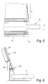
- FIG. 5 shows a schematic view of the winding shaft 31, on the example, three layers of the roller blind 21 over each other are wound up.
- a section 51 illustrates the transfer of the Guide element 41 from a winding position in a leadership position in the guide section 43.
- FIG. 6 Referenced.
- an alignment unit or deflection unit 54 Between a take-up shaft 31 and the guide rail 24 is shown an alignment unit or deflection unit 54, by which the orientation of the guide member 41 forcibly guided and relieved.
- a or a plurality of alignment units 54 may be provided.
- the alignment unit can also be designed rail-shaped, so that for example the Distance between the alignment unit 54 and the guide rail 24th is completely bridged according to FIG.
- the lateral edge 28 preferably engages centrally on the band-shaped guide element 41, so that this is rotated by 90 ° or folded, converted from a winding position to a developed state to become.
- the alignment unit 54 has, for example, a Guide slot 56 which has a middle position of, for example 45 ° occupies.
- the angle number of Slit 56 be formed larger or smaller.
- a continuous Guide element 41 instead of a continuous Guide element 41 a plurality of spaced apart Single guide elements are provided, which are also in a guide section 43 are guided. These individual guide elements can arranged at equal or irregular intervals to each other be. As a result, when winding a small outer circumference arise.
- the Philosophsabichnitt 43 further provided within the guide rail 24 is to the lateral sections, where a guide element 41st does not attack, within the slot 48 of the guide rail 24 stretched to be able to hold.
- the Guide section 43 a kind of lip-shaped protruding recess having.
- the guide element can be kederförmig be educated. This embodiment is thickened by a Edge area allows.
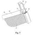
- Figure 7 is an alternative arrangement of a band-shaped guide element 41 to FIG. 3.
- the Guide portion 43 for the guide member 41 in parallel or in one acute angle to Rollobehang 21 provided.
- a guide portion 44 Adjacent to the guide section 43, a guide portion 44 is provided, which is a guide piece 27, which is advantageously bent relative to the tension rod 26 is, absorbs. This allows, for example, left and right of the plane of the blind sheet 21 guide portions 43 and 44th are arranged. This arrangement saves space.
- the guide sections 43 and 44 may be formed separately from each other or be formed in a common profile. Furthermore, can be provided that, for example, the guide portion 43 at a Profile with the guide portion 44 is fastened.
- guide portion 43rd is in the connecting region between the lateral edge 38 of the Rollobehanges 21 and the guide member 41 is a spacer or the Guide element 41 bulbous or provided with a protruding groove, so that the Rollobehang 21 without friction on an outer edge of the Guide section 43 can be passed.
- the guide portion 43 at an acute angle is arranged to the plane of the roller blind to a rectilinear lead out the edge portion of the roller blind 21 to the guide portion 43 to enable.
- the guide element 41 is preferably made Metal formed.
- the guide portion 43 may be formed of plastic be.
- other material combinations with good Gluteigenschaften be provided.
- an aluminum strip can also be used or a coated metal band or the like is provided be.
- This embodiment further has the advantage that in a arranged parallel or at an acute angle to the roller blind 21 Guide section 43 on a deflection unit for winding and unwinding the Rollobehanges 21 and waived on the take-up shaft 31 can be. Even at an angle of the guide portion 43 up to 60 ° to Rollobehang 21, wherein the guide portion 43 and the guide member 41 inclined to the plane of the roller blind 21 is a trouble-free winding can be done, in which the guide section 43 parallel to the roller blind 21 to rest on the take-up shaft 31 is coming.
- the outer dimensions can be matched to one another, that this in a simple way to a common profile, at least sections inserted into each other or can interlock. This advantageous embodiment also applies to the arrangement according to Figures 3 and 4.
Landscapes
- Engineering & Computer Science (AREA)
- Mechanical Engineering (AREA)
- Operating, Guiding And Securing Of Roll- Type Closing Members (AREA)
Abstract
Description
- Figur 1
- eine perspektivische Darstellung eines Heckscheibenbereiches von einem Personenkraftwagen mit einem geschlossenen Fensterrollo,
- Figur 2
- ein prinzipieller Aufbau eines Fensterrollos,
- Figur 3
- eine perspektivische Detaildarstellung einer an einer Führungsschiene geführten Rollobahn,
- Figur 4
- eine schematische Detaildarstellung einer Führungsschiene,
- Figur 5
- eine schematische Schnittdarstellung einer aufgewickelten und teilweise abgewickelten erfindungsgemäßen Rollobahn,
- Figur 6
- eine perspektivische Darstellung einer Führungsschiene und einer Aufwickelwelle, zwischen denen eine Ausrichteinheit angeordnet ist und
- Figur 7
- eine perspektivische Darstellung einer alternativen Ausführungsform einer Führungsschiene.
Claims (19)
- Fensterrollo für ein Kraftfahrzeug, mit wenigstens einer Aufwickelwelle (31), die drehbar gelagert ist, mit wenigstens einer Rollobahn (21), die mit einer Kante an der Wickelwelle (31) befestigt ist, mit einem längsverschieblichen Zugstab (26), der mit einer von der Wickelwelle (31) abliegenden Kante (28) verbunden ist, mit wenigstens zwei einander gegenüberliegenden Führungsschienen (24), von denen sich jede seitlich neben einer aufgespannten Rollobahn (21) erstreckt und die jeweils wenigstens einen Führungsabschnitt (44) enthalten, in denen zumindest ein Führungsstück (27) des Zugstabes (26) geführt ist und mit einer Antriebseinrichtung (34) zum Bewegen des Zugstabes (26) längs der Führungsschiene (24), dadurch gekennzeichnet, dass die Rollobahn (21) aus einem zumindest quer zur Auf- und Abwickelrichtung dehnbaren Material ausgebildet ist und deren seitlichen Kanten (38) zumindest abschnittsweise durch Führungselemente (41) in Führungsschienen (24) geführt sind.
- Fensterrollo nach Anspruch 1, dadurch gekennzeichnet, dass die Führungselemente (41) sich vollständig entlang den seitlichen Kanten (38) der Rollobahn (21) erstrecken und in Führungsschienen (24) geführt sind.
- Fensterrollo nach Anspruch 1 oder 2, dadurch gekennzeichnet, dass die an seitlichen Kanten (38) der Rollobahn (21) angeordneten Führungselemente (41) in den durch die Führungsstücke (27) geführten Führungsschienen (24) oder in jeweils separaten Führungsschienen (24) geführt sind.
- Fensterrollo nach einem der vorhergehenden Ansprüche, dadurch gekennzeichnet, dass die Führungsschiene (24) zumindest zwei einander zugeordnete Führungsabschnitte (43, 44) aufweist und vorzugsweise ein Führungsstück (27) des Zugstabes (26) den Führungsabschnitt (43) der Führungselemente (41) zur Anordnung im Führungsabschnitt (44) durchquert.
- Fensterrollo nach einem der vorhergehenden Ansprüche, dadurch gekennzeichnet, dass die an den seitlichen Kanten (38) vorgesehenen Führungselemente (41) zumindest an dem Zugstab (28) oder den Führungsstücken (27) angreifen.
- Fensterrollo nach einem der vorhergehenden Ansprüche, dadurch gekennzeichnet, dass zwischen einem der Aufwickelwelle (31) zugeordneten Ende (32) der Führungsschiene (24) und der Aufwickelwelle (31) zumindest eine Ausricht- oder Umlenkeinheit (54) vorgesehen ist, welche das Führungselement (41) aus einer Führungslage in eine Aufwickellage zumindest teilweise überführt.
- Fensterrollo nach Anspruch 6, dadurch gekennzeichnet, dass die zumindest eine Ausricht- oder Umlenkeinheit (54) für ein bandförmiges Führungselement (41) einen Führungsschlitz (56) aufweist, dessen Ausrichtung zwischen einer Aufwickellage und einer Führungslage des Führungselementes (41) vorgesehen ist und vorzugsweise eine gemittelte Zwischenposition aufweist.
- Fensterrollo nach einem der vorhergehenden Ansprüche, dadurch gekennzeichnet, dass der Führungsabschnitt (43) parallel oder in einem spitzen Winkel zur Rollobahn (21) vorgesehen ist.
- Fensterrollo nach Anspruch 8, dadurch gekennzeichnet, dass ein Führungsstück (27) gekröpft ausgebildet und benachbart am Führungsabschnitt (43) im Führungsabschnitt (44) geführt ist.
- Fensterrollo nach einem der vorhergehenden Ansprüche, dadurch gekennzeichnet, dass die Rollobahn (21) als Maschenware aus textilem Material, aus einem aus Textil und Kunststoff bestehenden Gemisch- oder Verbundmaterial, aus einem netzförmigen Kunststoff, aus einer Kunststoffbahn mit elastischen Anteilen oder aus einer elastischen Folie hergestellt ist.
- Fensterrollo nach einem der vorhergehenden Ansprüche, dadurch gekennzeichnet, dass die Rollobahn (21) eine Maschenbildung aufweist, deren Dehnfähigkeit quer zur Auf- und Abwickelrichtung der Rollobahn (21) größer als in Auf- und Abwickelrichtung der Rollobahn (21) ist.
- Fensterrollo nach einem der vorhergehenden Ansprüche, dadurch gekennzeichnet, dass die Rollobahn (21) in gedehntem und ungedehntem Zustand eine Abschattung von wenigstens 20 % bewirkt.
- Fensterrollo nach einem der vorhergehenden Ansprüche, dadurch gekennzeichnet, dass die seitlichen Kanten (38) der Rollobahn (21) in einem Bereich, in dem die Führungsschiene (24) ihren geringsten Abstand aufweist, eine Dehnung von wenigstens 3 % gegenüber einem unbelasteten Zustand aufweist.
- Fensterrollo nach einem der vorhergehenden Ansprüche, dadurch gekennzeichnet, dass die Rollobahn (21) um wenigstens 5 % zum unbelasteten Zustand in Querrichtung zur Auf- und Abwickelrichtung dehnbar ist.
- Fensterrollo nach einem der vorhergehenden Ansprüche, dadurch gekennzeichnet, dass die Führungselemente (41) an den seitlichen Kanten (38) aus einem zugfesten und biegefähigen Material, insbesondere als Zugschnur, ausgebildet sind.
- Fensterrollo nach Anspruch 15, dadurch gekennzeichnet, dass die Führungselemente (41) als Kunststoffband, als Textilband mit und ohne biegsamen Kern, als faserverstärktes Kunststoffband, insbesondere als Teflonband oder als Metallband, ausgebildet sind.
- Fensterrollo nach einem der vorhergehenden Ansprüche, dadurch gekennzeichnet, dass die seitliche Kante (38) zum zumindest einen Führungselement (41) durch Klemmen, Kleben, Einkleben, Nähen, Schweißen, zumindest durch Wärme oder Ultraschall, Einwirken oder Pressen befestigt ist.
- Fensterrollo nach einem der vorhergehenden Ansprüche, dadurch gekennzeichnet, dass eine wandernde Aufwickelwelle (31) vorgesehen ist.
- Fensterrollo nach einem der vorhergehenden Ansprüche, dadurch gekennzeichnet, dass die dehnbare Rollobahn (21) für Heckscheiben, Heckklappen, Seitenfenster, Dachfenster oder Frontscheiben einsetzbar ist.
Applications Claiming Priority (2)
| Application Number | Priority Date | Filing Date | Title |
|---|---|---|---|
| DE102004017023 | 2004-04-02 | ||
| DE200410017023 DE102004017023A1 (de) | 2004-04-02 | 2004-04-02 | Fensterrollo für Kraftfahrzeuge |
Publications (3)
| Publication Number | Publication Date |
|---|---|
| EP1582386A2 true EP1582386A2 (de) | 2005-10-05 |
| EP1582386A3 EP1582386A3 (de) | 2008-12-31 |
| EP1582386B1 EP1582386B1 (de) | 2012-12-19 |
Family
ID=34877745
Family Applications (1)
| Application Number | Title | Priority Date | Filing Date |
|---|---|---|---|
| EP20050007288 Ceased EP1582386B1 (de) | 2004-04-02 | 2005-04-04 | Fensterrollo für Kraftfahrzeuge |
Country Status (2)
| Country | Link |
|---|---|
| EP (1) | EP1582386B1 (de) |
| DE (1) | DE102004017023A1 (de) |
Cited By (8)
| Publication number | Priority date | Publication date | Assignee | Title |
|---|---|---|---|---|
| DE102005030973A1 (de) * | 2005-06-30 | 2007-01-11 | Webasto Ag | Rolloanordnung für ein Kraftfahrzeug |
| EP2014493A3 (de) * | 2007-07-11 | 2010-12-22 | BOS GmbH & Co. KG | Seitenführung für Beschattungsrollo und Beschattungsrollo für Kraftfahrzeuge |
| DE102007029290B4 (de) * | 2007-06-18 | 2011-07-28 | BOS GmbH & Co. KG, 73760 | Flexible Schutzabdeckung |
| WO2014090759A1 (de) * | 2012-12-10 | 2014-06-19 | Bos Gmbh & Co. Kg | Schutzvorrichtung, insbesondere beschattungsvorrichtung, für einen fahrzeuginnenraum eines kraftfahrzeugs |
| CN105313657A (zh) * | 2014-08-01 | 2016-02-10 | 博斯股份有限两合公司 | 用于机动车的透明的平面件的遮蔽设备 |
| CN107672532A (zh) * | 2017-11-10 | 2018-02-09 | 昆山誉球模塑有限公司 | 一种全程程导轨的遮物帘轻压自动回收机构 |
| CN110481284A (zh) * | 2019-08-20 | 2019-11-22 | 宁波帅特龙集团有限公司 | 一种汽车侧窗遮阳帘总成的制备工艺 |
| CN110626157A (zh) * | 2019-11-08 | 2019-12-31 | 昆山誉球模塑有限公司 | 一种弧形卷轴联动式汽车天窗遮阳帘 |
Families Citing this family (10)
| Publication number | Priority date | Publication date | Assignee | Title |
|---|---|---|---|---|
| DE102005062427A1 (de) * | 2005-12-23 | 2007-07-05 | Bos Gmbh & Co. Kg | Rollo zur Vollbeschattung einer Heckscheibe |
| DE102008012202B4 (de) * | 2008-03-03 | 2010-05-27 | Bos Gmbh & Co. Kg | Dachfensterrollo mit Spanneinrichtung |
| DE102008015853A1 (de) * | 2008-03-27 | 2009-10-01 | Rehau Ag + Co | Beheizbare Kunststoffscheibe und Verfahren zu deren Herstellung |
| DE202010006678U1 (de) | 2010-05-11 | 2010-11-11 | GM Global Technology Operations, Inc., Detroit | Fahrzeuginnenabdeckung |
| JP6118642B2 (ja) | 2013-05-31 | 2017-04-19 | ベバスト ジャパン株式会社 | ロールシェード装置 |
| DE102014215153B4 (de) | 2014-08-01 | 2022-01-27 | Bos Gmbh & Co. Kg | Beschattungsvorrichtung für ein transparentes Flächenteil eines Kraftfahrzeugs |
| FR3044974B1 (fr) | 2015-12-14 | 2017-12-29 | Advanced Comfort Systems France Sas - Acs France | Dispositif d'occultation d'une surface vitree d'un pavillon de vehicule automobile a rails non paralleles. |
| DE102016108903A1 (de) * | 2016-05-13 | 2017-11-16 | Webasto SE | Rolloanordnung mit seitlichen Führungselementen |
| DE102018126601A1 (de) * | 2018-10-25 | 2020-04-30 | Webasto SE | Rolloanordnung mit Zugspriegel für Rollobahn |
| DE102019108368A1 (de) * | 2019-04-01 | 2020-10-01 | Lisa Dräxlmaier GmbH | Beschattungssystem für ein fahrzeugfenster |
Citations (1)
| Publication number | Priority date | Publication date | Assignee | Title |
|---|---|---|---|---|
| EP1188591A1 (de) | 2000-09-19 | 2002-03-20 | BOS GmbH & Co. KG | Fensterrollo für gekrümmte oder nicht rechteckige Fahrzeugfenster |
Family Cites Families (3)
| Publication number | Priority date | Publication date | Assignee | Title |
|---|---|---|---|---|
| DE10057760B4 (de) * | 2000-11-22 | 2004-08-12 | Bos Gmbh & Co. Kg | Fensterrollo mit Zentriereinrichtung für den Zugstab |
| WO2002042103A1 (en) * | 2000-11-27 | 2002-05-30 | Vardan Penesyan | Front and backscreens blinds of a motor vehicle |
| US7393041B2 (en) * | 2003-07-24 | 2008-07-01 | O.E. Sunshades Limited | Sunblind |
-
2004
- 2004-04-02 DE DE200410017023 patent/DE102004017023A1/de not_active Withdrawn
-
2005
- 2005-04-04 EP EP20050007288 patent/EP1582386B1/de not_active Ceased
Patent Citations (1)
| Publication number | Priority date | Publication date | Assignee | Title |
|---|---|---|---|---|
| EP1188591A1 (de) | 2000-09-19 | 2002-03-20 | BOS GmbH & Co. KG | Fensterrollo für gekrümmte oder nicht rechteckige Fahrzeugfenster |
Cited By (12)
| Publication number | Priority date | Publication date | Assignee | Title |
|---|---|---|---|---|
| DE102005030973A1 (de) * | 2005-06-30 | 2007-01-11 | Webasto Ag | Rolloanordnung für ein Kraftfahrzeug |
| DE102007029290B4 (de) * | 2007-06-18 | 2011-07-28 | BOS GmbH & Co. KG, 73760 | Flexible Schutzabdeckung |
| EP2014493A3 (de) * | 2007-07-11 | 2010-12-22 | BOS GmbH & Co. KG | Seitenführung für Beschattungsrollo und Beschattungsrollo für Kraftfahrzeuge |
| US8800635B2 (en) | 2007-07-11 | 2014-08-12 | Bos Gmbh & Co. Kg | Lateral guide for shading roller blind, and shading roller blind for motor vehicles |
| WO2014090759A1 (de) * | 2012-12-10 | 2014-06-19 | Bos Gmbh & Co. Kg | Schutzvorrichtung, insbesondere beschattungsvorrichtung, für einen fahrzeuginnenraum eines kraftfahrzeugs |
| CN105073463A (zh) * | 2012-12-10 | 2015-11-18 | 博斯股份有限两合公司 | 用于机动车的车辆内部空间的保护装置、尤其遮蔽装置 |
| CN105313657A (zh) * | 2014-08-01 | 2016-02-10 | 博斯股份有限两合公司 | 用于机动车的透明的平面件的遮蔽设备 |
| JP2016034827A (ja) * | 2014-08-01 | 2016-03-17 | ベーオーエス ゲゼルシャフト ミット ベシュレンクテル ハフツング ウント コンパニー コマンディトゲゼルシャフト | 自動車の透明な面部分用の遮光装置 |
| CN107672532A (zh) * | 2017-11-10 | 2018-02-09 | 昆山誉球模塑有限公司 | 一种全程程导轨的遮物帘轻压自动回收机构 |
| CN110481284A (zh) * | 2019-08-20 | 2019-11-22 | 宁波帅特龙集团有限公司 | 一种汽车侧窗遮阳帘总成的制备工艺 |
| CN110481284B (zh) * | 2019-08-20 | 2020-10-09 | 宁波帅特龙集团有限公司 | 一种汽车侧窗遮阳帘总成的制备工艺 |
| CN110626157A (zh) * | 2019-11-08 | 2019-12-31 | 昆山誉球模塑有限公司 | 一种弧形卷轴联动式汽车天窗遮阳帘 |
Also Published As
| Publication number | Publication date |
|---|---|
| DE102004017023A1 (de) | 2005-10-20 |
| EP1582386A3 (de) | 2008-12-31 |
| EP1582386B1 (de) | 2012-12-19 |
Similar Documents
| Publication | Publication Date | Title |
|---|---|---|
| EP1582386B1 (de) | Fensterrollo für Kraftfahrzeuge | |
| EP1010559B1 (de) | Sonnenrollo für ein Kraftfahrzeugdach | |
| EP1449692B1 (de) | Sonnenschutzsystem für ein Kraftfahrzeug | |
| EP1612070B1 (de) | Fensterrollo für gekrümmte oder nicht rechteckige Fahrzeugfenster | |
| EP1182066B1 (de) | Fahrzeug mit Sonnenschutzrollo im Dach | |
| EP1588880B1 (de) | Rollo für ein Schiebedachsystem | |
| EP2455245A2 (de) | Flexible Schutzabdeckung | |
| DE10306951A1 (de) | Sonnenschutzsystem für ein Kraftfahrzeug | |
| EP2874837B1 (de) | Schiebehimmel für ein kraftfahrzeug | |
| DE102016015397A1 (de) | Rollovorrichtung an einem Fahrzeugdach | |
| DE19910950C1 (de) | Schiebehimmel für ein Fahrzeugdach | |
| DE19741863C2 (de) | Schutzvorrichtung für eine gekrümmte Scheibenanordnung eines Kraftfahrzeugs | |
| DE19844779C1 (de) | Abdeckvorrichtung für eine Öffnung in einem Fahrzeugdach | |
| DE10240582B4 (de) | Rolloplane als Sonnenschutz | |
| EP1409830B1 (de) | Pneumatischer rollladen | |
| DE10205117C1 (de) | Rolloanordnung für ein Fahrzeugdach | |
| DE102004045726B3 (de) | Abdeckvorrichtung für eine Fahrzeugverglasung | |
| DE19856868A1 (de) | Dachanordnung | |
| DE102012102116B4 (de) | Baugruppe mit einer Rollobahn, und Dachanordnung | |
| DE10245901A1 (de) | Rolloanordnung für Fahrzeugscheiben | |
| DE102004020337A1 (de) | Fahrzeugdach mit einer Rolloanordnung | |
| DE19917292A1 (de) | Blendschutzeinrichtung für Kraftfahrzeuge | |
| DE102013207920A1 (de) | Schutzvorrichtung für einen Fahrzeuginnenraum | |
| DE4337311C1 (de) | Sonnenschutz für eine Scheibe | |
| DE19536510A1 (de) | Fensterrollo, insbesondere für ein Kraftfahrzeug |
Legal Events
| Date | Code | Title | Description |
|---|---|---|---|
| PUAI | Public reference made under article 153(3) epc to a published international application that has entered the european phase |
Free format text: ORIGINAL CODE: 0009012 |
|
| AK | Designated contracting states |
Kind code of ref document: A2 Designated state(s): AT BE BG CH CY CZ DE DK EE ES FI FR GB GR HU IE IS IT LI LT LU MC NL PL PT RO SE SI SK TR |
|
| AX | Request for extension of the european patent |
Extension state: AL BA HR LV MK YU |
|
| RAP1 | Party data changed (applicant data changed or rights of an application transferred) |
Owner name: BOS GMBH & CO. KG |
|
| PUAL | Search report despatched |
Free format text: ORIGINAL CODE: 0009013 |
|
| AK | Designated contracting states |
Kind code of ref document: A3 Designated state(s): AT BE BG CH CY CZ DE DK EE ES FI FR GB GR HU IE IS IT LI LT LU MC NL PL PT RO SE SI SK TR |
|
| AX | Request for extension of the european patent |
Extension state: AL BA HR LV MK YU |
|
| 17P | Request for examination filed |
Effective date: 20090307 |
|
| AKX | Designation fees paid |
Designated state(s): DE FR SE |
|
| 17Q | First examination report despatched |
Effective date: 20091210 |
|
| GRAP | Despatch of communication of intention to grant a patent |
Free format text: ORIGINAL CODE: EPIDOSNIGR1 |
|
| GRAS | Grant fee paid |
Free format text: ORIGINAL CODE: EPIDOSNIGR3 |
|
| GRAA | (expected) grant |
Free format text: ORIGINAL CODE: 0009210 |
|
| RIN1 | Information on inventor provided before grant (corrected) |
Inventor name: DER ERFINDER HAT AUF SEINE NENNUNG VERZICHTET. |
|
| AK | Designated contracting states |
Kind code of ref document: B1 Designated state(s): DE FR SE |
|
| REG | Reference to a national code |
Ref country code: DE Ref legal event code: R096 Ref document number: 502005013343 Country of ref document: DE Effective date: 20130221 |
|
| PG25 | Lapsed in a contracting state [announced via postgrant information from national office to epo] |
Ref country code: SE Free format text: LAPSE BECAUSE OF FAILURE TO SUBMIT A TRANSLATION OF THE DESCRIPTION OR TO PAY THE FEE WITHIN THE PRESCRIBED TIME-LIMIT Effective date: 20121219 |
|
| PLBE | No opposition filed within time limit |
Free format text: ORIGINAL CODE: 0009261 |
|
| STAA | Information on the status of an ep patent application or granted ep patent |
Free format text: STATUS: NO OPPOSITION FILED WITHIN TIME LIMIT |
|
| 26N | No opposition filed |
Effective date: 20130920 |
|
| REG | Reference to a national code |
Ref country code: DE Ref legal event code: R097 Ref document number: 502005013343 Country of ref document: DE Effective date: 20130920 |
|
| REG | Reference to a national code |
Ref country code: FR Ref legal event code: PLFP Year of fee payment: 12 |
|
| REG | Reference to a national code |
Ref country code: FR Ref legal event code: PLFP Year of fee payment: 13 |
|
| PGFP | Annual fee paid to national office [announced via postgrant information from national office to epo] |
Ref country code: FR Payment date: 20170428 Year of fee payment: 13 Ref country code: DE Payment date: 20170427 Year of fee payment: 13 |
|
| REG | Reference to a national code |
Ref country code: DE Ref legal event code: R119 Ref document number: 502005013343 Country of ref document: DE |
|
| PG25 | Lapsed in a contracting state [announced via postgrant information from national office to epo] |
Ref country code: DE Free format text: LAPSE BECAUSE OF NON-PAYMENT OF DUE FEES Effective date: 20181101 |
|
| PG25 | Lapsed in a contracting state [announced via postgrant information from national office to epo] |
Ref country code: FR Free format text: LAPSE BECAUSE OF NON-PAYMENT OF DUE FEES Effective date: 20180430 |