EP1582404A2 - Dispositif de sécurité pour une rampe - Google Patents
Dispositif de sécurité pour une rampe Download PDFInfo
- Publication number
- EP1582404A2 EP1582404A2 EP05380058A EP05380058A EP1582404A2 EP 1582404 A2 EP1582404 A2 EP 1582404A2 EP 05380058 A EP05380058 A EP 05380058A EP 05380058 A EP05380058 A EP 05380058A EP 1582404 A2 EP1582404 A2 EP 1582404A2
- Authority
- EP
- European Patent Office
- Prior art keywords
- support
- shaft
- walls
- supports
- inner support
- Prior art date
- Legal status (The legal status is an assumption and is not a legal conclusion. Google has not performed a legal analysis and makes no representation as to the accuracy of the status listed.)
- Withdrawn
Links
- 238000004873 anchoring Methods 0.000 claims 1
- 238000000605 extraction Methods 0.000 description 5
- 230000000284 resting effect Effects 0.000 description 3
- 230000002829 reductive effect Effects 0.000 description 2
- 230000003100 immobilizing effect Effects 0.000 description 1
- 230000000670 limiting effect Effects 0.000 description 1
- 230000036961 partial effect Effects 0.000 description 1
Images




Classifications
-
- A—HUMAN NECESSITIES
- A61—MEDICAL OR VETERINARY SCIENCE; HYGIENE
- A61G—TRANSPORT, PERSONAL CONVEYANCES, OR ACCOMMODATION SPECIALLY ADAPTED FOR PATIENTS OR DISABLED PERSONS; OPERATING TABLES OR CHAIRS; CHAIRS FOR DENTISTRY; FUNERAL DEVICES
- A61G3/00—Ambulance aspects of vehicles; Vehicles with special provisions for transporting patients or disabled persons, or their personal conveyances, e.g. for facilitating access of, or for loading, wheelchairs
- A61G3/02—Loading or unloading personal conveyances; Facilitating access of patients or disabled persons to, or exit from, vehicles
- A61G3/06—Transfer using ramps, lifts or the like
- A61G3/061—Transfer using ramps, lifts or the like using ramps
-
- A—HUMAN NECESSITIES
- A61—MEDICAL OR VETERINARY SCIENCE; HYGIENE
- A61G—TRANSPORT, PERSONAL CONVEYANCES, OR ACCOMMODATION SPECIALLY ADAPTED FOR PATIENTS OR DISABLED PERSONS; OPERATING TABLES OR CHAIRS; CHAIRS FOR DENTISTRY; FUNERAL DEVICES
- A61G3/00—Ambulance aspects of vehicles; Vehicles with special provisions for transporting patients or disabled persons, or their personal conveyances, e.g. for facilitating access of, or for loading, wheelchairs
- A61G3/02—Loading or unloading personal conveyances; Facilitating access of patients or disabled persons to, or exit from, vehicles
- A61G3/06—Transfer using ramps, lifts or the like
- A61G3/067—Transfer using ramps, lifts or the like with compartment for horizontally storing the ramp or lift
-
- B—PERFORMING OPERATIONS; TRANSPORTING
- B60—VEHICLES IN GENERAL
- B60P—VEHICLES ADAPTED FOR LOAD TRANSPORTATION OR TO TRANSPORT, TO CARRY, OR TO COMPRISE SPECIAL LOADS OR OBJECTS
- B60P1/00—Vehicles predominantly for transporting loads and modified to facilitate loading, consolidating the load, or unloading
- B60P1/43—Vehicles predominantly for transporting loads and modified to facilitate loading, consolidating the load, or unloading using a loading ramp mounted on the vehicle
-
- B—PERFORMING OPERATIONS; TRANSPORTING
- B60—VEHICLES IN GENERAL
- B60P—VEHICLES ADAPTED FOR LOAD TRANSPORTATION OR TO TRANSPORT, TO CARRY, OR TO COMPRISE SPECIAL LOADS OR OBJECTS
- B60P1/00—Vehicles predominantly for transporting loads and modified to facilitate loading, consolidating the load, or unloading
- B60P1/43—Vehicles predominantly for transporting loads and modified to facilitate loading, consolidating the load, or unloading using a loading ramp mounted on the vehicle
- B60P1/431—Vehicles predominantly for transporting loads and modified to facilitate loading, consolidating the load, or unloading using a loading ramp mounted on the vehicle the ramp being stored under the loading floor when not in use
-
- F—MECHANICAL ENGINEERING; LIGHTING; HEATING; WEAPONS; BLASTING
- F16—ENGINEERING ELEMENTS AND UNITS; GENERAL MEASURES FOR PRODUCING AND MAINTAINING EFFECTIVE FUNCTIONING OF MACHINES OR INSTALLATIONS; THERMAL INSULATION IN GENERAL
- F16P—SAFETY DEVICES IN GENERAL; SAFETY DEVICES FOR PRESSES
- F16P3/00—Safety devices acting in conjunction with the control or operation of a machine; Control arrangements requiring the simultaneous use of two or more parts of the body
- F16P3/12—Safety devices acting in conjunction with the control or operation of a machine; Control arrangements requiring the simultaneous use of two or more parts of the body with means, e.g. feelers, which in case of the presence of a body part of a person in or near the danger zone influence the control or operation of the machine
Definitions
- the present invention refers to a safety device for extracting vehicle access ramps, particularly intended for being installed in ramps assembled on the vehicles themselves for facilitating access for people with reduced mobility.
- Ramps of the type indicated are generally formed by a casing or box of general right prismatic configuration, small height, square or rectangular-plan form, which is open at one of its walls. Housed within this casing is a plate, hereinafter called step, which is extractable when the vehicle is stopped so as to aid people with mobility problems to get on or off. Housed within the casing is a mechanism responsible for extracting or retracting the step.
- the object of the present invention is to solve the problem set forth by means of a device of simple constitution and reduced cost which can be easily incorporated to the vehicle access ramp, assuring the immobilization of the step when it is in the extraction or retraction phase, provided that a weight exceeding a preset value is placed on said step, said value being chosen such that the immobilization of the step is assured not only by the weight of an adult person but also by the weight of a child.
- the device of the invention thus eliminates the risk of accidents due to a person accidentally treading on the step when the latter is in the extraction or retraction phase.
- the device of the invention is formed by two grooved supports coupled one inside the other in the same direction, both supports being able to have a U-shaped profile or section, of side branches that are straight and perpendicular to the central branch.
- the walls of the two supports are perpendicularly traversed by first and second shafts which are located the same distance from the central branch of the grooved supports. Assembled on these two shafts are two freely rotatable wheels projecting with respect to the free longitudinal edge of the grooved supports.
- the first shaft traverses the walls of the outer support through respective oblong holes in an approximately vertical direction such that the inner support may swivel on the second shaft with respect to the outer support between an upper position in which the wheel assembled on the first shaft is located at a greater height than the wheel assembled on the second shaft, and a lower position in which the two wheels are approximately at the same height.
- the two supports are connected by means of a spring constantly driving the inner support towards its upper position.
- the oblong holes of the walls of the outer support through which the first one of the shafts passes will be of a slightly arched design, with a center of curvature in the second shaft.
- Two supports such as that described will preferably be arranged in each ramp close to the open wall through which the ramp can be extracted.
- the devices will be located such that if a weight exceeding the preset limit is placed on the ramp during the extraction or retraction phase thereof, said ramp will act on the safety device, sending the corresponding signal to the actuation mechanism for its immobilization.
- Figure 1 shows a vehicle access ramp, of a customary constitution, formed by a box or casing 1 of right prismatic configuration, rectangular-plan form, small height, which is open at one of its side walls 2 and partially at the upper base 3.
- a step 4 Housed within this box or casing 1 is a step 4 that is extractable through the wall 2, as well as means for guiding the step 4 in its entrance and exit movements and an actuation mechanism responsible for causing such movements.
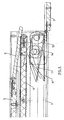
- the upper base of the box has, close to the open wall 2, a fixed crossbar 5 to which a plate 6 is articulated which, in the extracted position of the step 4, occupies a tilted position almost in extension with that of said step, as can be seen in Figure 2, whereas when the step is fully retracted or housed in the box, as shown in Figure 6, it will be in a notably horizontal position upon lifting the gate 7 closing the open front wall of the casing, resting on the upper edge of said gate.
- the walkway 1 includes a safety device by means of which the movement of the step 4 in its outward or inward movement is stopped if a weight having a magnitude exceeding a preset value is placed on said step.
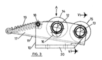
- this device is formed by two grooved structure supports coupled together one inside the other in the same direction, an outer one having reference number 10, and another inner one with reference number 11, both supports having in the example represented in the drawings a U-shaped cross section, the side branches of which are perpendicular to the central branch.
- the side branches or walls of the two supports are perpendicularly traversed by the first shaft 12 and by a second shaft 13, both located an equal distance from the bottom of the inner support 11.
- Two freely rotatable wheels 14 and 15 are assembled on these shafts.
- the shaft 12 traverses the walls of the outer support 10 through oblong holes 16 having a slightly arched trajectory with a center of curvature in shaft 13.
- the support 11 projects through the side of the wheel 14 with respect to the support 10 in a portion 17, between the end of which support and a pin 18 assembled between the walls of support 10 a tension spring 19 is arranged which constantly drives the support 11 towards the position shown in Figure 3, in which the shaft 12 is moved towards the upper limit of the oblong holes 16.
- the support 17 will swivel in a downward direction, about shaft 13, until the central branch or bottom of said support rests on the central branch or bottom of the support 10.
- the central branch or bottom of the outer support 10 extends on one side into a longitudinal wing 20 provided with holes 21 for the fixing thereof inside the casing 1 of the ramp, as will be explained below.
- two devices such as those represented in Figures 3 to 5 are arranged on the bottom of the box 1, under the plate 6.
- the devices are fixed to the bottom of the box 1 by means of the wing 20, with the shafts 12 and 13 perpendicular to the direction of movement of the step 4.
- the support 11 can occupy its raised position, said step also being tangent to wheel 14, similar to Figure 6.
- a weight W with a preset value acts on the step, said step swivels until occupying position 4', in which it pushes the wheel 14 in a downward direction until it occupies position 14', the support 11 being moved to position 11'.
- a circuit is closed by means of a contact or the like, immobilizing the actuation mechanism of the step 4, which thus remains stopped.
- the weight W corresponds to a person accidentally resting on the step 4 during movement, it will cause its immobilization, preventing the person from being able to fall. It thus has a safety catch against movement of the step when a weight equal to or greater than a pre-established value is placed on the step.
Landscapes
- Engineering & Computer Science (AREA)
- Health & Medical Sciences (AREA)
- Public Health (AREA)
- Mechanical Engineering (AREA)
- Veterinary Medicine (AREA)
- Life Sciences & Earth Sciences (AREA)
- Animal Behavior & Ethology (AREA)
- General Health & Medical Sciences (AREA)
- General Engineering & Computer Science (AREA)
- Transportation (AREA)
- Vehicle Step Arrangements And Article Storage (AREA)
- Emergency Lowering Means (AREA)
- Handcart (AREA)
- Vehicle Body Suspensions (AREA)
Applications Claiming Priority (2)
| Application Number | Priority Date | Filing Date | Title |
|---|---|---|---|
| ES200400820 | 2004-04-02 | ||
| ES200400820A ES2259255B1 (es) | 2004-04-02 | 2004-04-02 | Dispositivo de seguridad para la extraccion de rampas de acceso a vehiculos. |
Publications (2)
| Publication Number | Publication Date |
|---|---|
| EP1582404A2 true EP1582404A2 (fr) | 2005-10-05 |
| EP1582404A3 EP1582404A3 (fr) | 2006-03-01 |
Family
ID=34878439
Family Applications (1)
| Application Number | Title | Priority Date | Filing Date |
|---|---|---|---|
| EP05380058A Withdrawn EP1582404A3 (fr) | 2004-04-02 | 2005-04-01 | Dispositif de sécurité pour une rampe |
Country Status (2)
| Country | Link |
|---|---|
| EP (1) | EP1582404A3 (fr) |
| ES (1) | ES2259255B1 (fr) |
Cited By (3)
| Publication number | Priority date | Publication date | Assignee | Title |
|---|---|---|---|---|
| EP1598040A3 (fr) * | 2004-05-21 | 2006-03-08 | Fine Access, S.L. | Rampe d'accès pour véhicules |
| WO2013138661A1 (fr) | 2012-03-16 | 2013-09-19 | Ricon Corp. | Système de détection de charge pour agencement de levage de fauteuil roulant |
| CN112026622A (zh) * | 2019-06-03 | 2020-12-04 | 爱信轻金属株式会社 | 车辆用斜坡装置 |
Family Cites Families (5)
| Publication number | Priority date | Publication date | Assignee | Title |
|---|---|---|---|---|
| GB669102A (en) * | 1949-03-14 | 1952-03-26 | Donald Claude Sharp | Safety device for bending presses and the like |
| GB811385A (en) * | 1956-08-23 | 1959-04-02 | J P Udal Ltd | Safety devices for use with machines |
| GB1331316A (en) * | 1972-04-18 | 1973-09-26 | Black G A | Haulage apparatus and the like |
| US6238169B1 (en) * | 1998-05-01 | 2001-05-29 | The Braun Corporation | Dual function inboard barrier/bridgeplate assembly for wheelchair lifts |
| ES2160513B1 (es) * | 1999-09-22 | 2002-06-01 | Fine Products S A | Rampa de acceso para personas de movilidad reducida. |
-
2004
- 2004-04-02 ES ES200400820A patent/ES2259255B1/es not_active Expired - Fee Related
-
2005
- 2005-04-01 EP EP05380058A patent/EP1582404A3/fr not_active Withdrawn
Cited By (8)
| Publication number | Priority date | Publication date | Assignee | Title |
|---|---|---|---|---|
| EP1598040A3 (fr) * | 2004-05-21 | 2006-03-08 | Fine Access, S.L. | Rampe d'accès pour véhicules |
| ES2258894A1 (es) * | 2004-05-21 | 2006-09-01 | Fine Access S.L. | Rampa para el acceso a vehiculos. |
| ES2258894B1 (es) * | 2004-05-21 | 2007-11-16 | Fine Access S.L. | Rampa para el acceso a vehiculos. |
| WO2013138661A1 (fr) | 2012-03-16 | 2013-09-19 | Ricon Corp. | Système de détection de charge pour agencement de levage de fauteuil roulant |
| EP2825145A4 (fr) * | 2012-03-16 | 2015-11-18 | Ricon Corp | Système de détection de charge pour agencement de levage de fauteuil roulant |
| US9456940B2 (en) | 2012-03-16 | 2016-10-04 | Ricon Corp. | Load sensing system for wheelchair lift arrangement |
| CN112026622A (zh) * | 2019-06-03 | 2020-12-04 | 爱信轻金属株式会社 | 车辆用斜坡装置 |
| CN112026622B (zh) * | 2019-06-03 | 2022-10-18 | 爱信轻金属株式会社 | 车辆用斜坡装置 |
Also Published As
| Publication number | Publication date |
|---|---|
| ES2259255A1 (es) | 2006-09-16 |
| EP1582404A3 (fr) | 2006-03-01 |
| ES2259255B1 (es) | 2007-09-16 |
Similar Documents
| Publication | Publication Date | Title |
|---|---|---|
| US6802095B1 (en) | Ramp assembly having a lift and lock mechanism | |
| CA2229680C (fr) | Structure de rampe mobile | |
| AU692683B2 (en) | An improved movable ramp assembly | |
| US4531472A (en) | Indicator and barrier assembly for parking space | |
| ES2623394T3 (es) | Rampa que tiene una barrera lateral | |
| ES2215550T3 (es) | Accesorio para la extraccion completa de cajones y acoplamiento. | |
| WO2005108161A1 (fr) | Dispositif de pontage | |
| KR101603164B1 (ko) | 열차승강장 발빠짐 방지용 접철식 자동길이 조절 안전발판 | |
| JPH0657764U (ja) | プラットホーム | |
| KR101058879B1 (ko) | 도시철도차량의 안전발판 | |
| KR101518136B1 (ko) | 승강장용 안전브릿지 시스템 | |
| WO2003064208A1 (fr) | Ensemble rampe possedant un mecanisme de levage et de verrouillage | |
| KR100969560B1 (ko) | 보관 및 사용이 용이한 철도차량용 휠체어 승하차장치 | |
| KR101998714B1 (ko) | 기계식 리프트 차량 | |
| KR200454487Y1 (ko) | 철도차량의 출입문 발판부재 | |
| JP3797271B2 (ja) | マンホール用収納式タラップ | |
| EP1555002A1 (fr) | Rampe pour acces a des vehicules | |
| EP1275806A2 (fr) | Arrêt pour portails, portes, portes automatiques et similaires | |
| JPH0649288U (ja) | 車輪後退防止装置 | |
| CN114531871B (zh) | 电梯设备 | |
| KR101216585B1 (ko) | 미닫이 창문에 구비된 가동틀의 이탈방지장치 | |
| KR200434281Y1 (ko) | 리프트 카의 천정 점검구용 미닫이 도어 | |
| JP2710295B2 (ja) | 昇降装置 | |
| JP2002295155A (ja) | 伸縮門扉の転倒防止装置 | |
| EP1598040A2 (fr) | Rampe d'accès pour véhicules |
Legal Events
| Date | Code | Title | Description |
|---|---|---|---|
| PUAI | Public reference made under article 153(3) epc to a published international application that has entered the european phase |
Free format text: ORIGINAL CODE: 0009012 |
|
| AK | Designated contracting states |
Kind code of ref document: A2 Designated state(s): AT BE BG CH CY CZ DE DK EE ES FI FR GB GR HU IE IS IT LI LT LU MC NL PL PT RO SE SI SK TR |
|
| AX | Request for extension of the european patent |
Extension state: AL BA HR LV MK YU |
|
| PUAL | Search report despatched |
Free format text: ORIGINAL CODE: 0009013 |
|
| AK | Designated contracting states |
Kind code of ref document: A3 Designated state(s): AT BE BG CH CY CZ DE DK EE ES FI FR GB GR HU IE IS IT LI LT LU MC NL PL PT RO SE SI SK TR |
|
| AX | Request for extension of the european patent |
Extension state: AL BA HR LV MK YU |
|
| AKX | Designation fees paid | ||
| REG | Reference to a national code |
Ref country code: DE Ref legal event code: 8566 |
|
| STAA | Information on the status of an ep patent application or granted ep patent |
Free format text: STATUS: THE APPLICATION IS DEEMED TO BE WITHDRAWN |
|
| 18D | Application deemed to be withdrawn |
Effective date: 20060902 |