EP1582441A2 - Longeron d'un carrosserie autoportant d'un véhicule automobile - Google Patents
Longeron d'un carrosserie autoportant d'un véhicule automobile Download PDFInfo
- Publication number
- EP1582441A2 EP1582441A2 EP05006208A EP05006208A EP1582441A2 EP 1582441 A2 EP1582441 A2 EP 1582441A2 EP 05006208 A EP05006208 A EP 05006208A EP 05006208 A EP05006208 A EP 05006208A EP 1582441 A2 EP1582441 A2 EP 1582441A2
- Authority
- EP
- European Patent Office
- Prior art keywords
- sill
- motor vehicle
- reinforcing element
- vehicle according
- side frame
- Prior art date
- Legal status (The legal status is an assumption and is not a legal conclusion. Google has not performed a legal analysis and makes no representation as to the accuracy of the status listed.)
- Granted
Links
- 239000004033 plastic Substances 0.000 claims abstract description 11
- 239000000463 material Substances 0.000 claims abstract description 5
- 230000006378 damage Effects 0.000 claims abstract description 4
- 239000002184 metal Substances 0.000 claims abstract description 3
- 230000003014 reinforcing effect Effects 0.000 claims description 39
- 230000002093 peripheral effect Effects 0.000 claims description 2
- 230000002787 reinforcement Effects 0.000 abstract description 11
- 229920001169 thermoplastic Polymers 0.000 description 2
- 239000004416 thermosoftening plastic Substances 0.000 description 2
- 238000004519 manufacturing process Methods 0.000 description 1
- 238000000465 moulding Methods 0.000 description 1
- 239000007787 solid Substances 0.000 description 1
Images
Classifications
-
- B—PERFORMING OPERATIONS; TRANSPORTING
- B62—LAND VEHICLES FOR TRAVELLING OTHERWISE THAN ON RAILS
- B62D—MOTOR VEHICLES; TRAILERS
- B62D25/00—Superstructure or monocoque structure sub-units; Parts or details thereof not otherwise provided for
- B62D25/20—Floors or bottom sub-units
- B62D25/2072—Floor protection, e.g. from corrosion or scratching
-
- B—PERFORMING OPERATIONS; TRANSPORTING
- B62—LAND VEHICLES FOR TRAVELLING OTHERWISE THAN ON RAILS
- B62D—MOTOR VEHICLES; TRAILERS
- B62D25/00—Superstructure or monocoque structure sub-units; Parts or details thereof not otherwise provided for
- B62D25/20—Floors or bottom sub-units
- B62D25/2081—Jack receiving devices
Definitions
- the invention relates to a motor vehicle according to the preamble of claim 1.
- the object of the invention is to provide a motor vehicle, wherein the sill has an additional stiffening.
- a reinforcement is provided, through which a bottom-side outer wall of the Schweller and an opposite bottom wall of a side frame in front is protected from damage. This is in a cavity between the Bottom wall of the side frame and the opposite outer wall of the Sills a reinforcing element arranged so that the cavity is filled is and at a force from outside the force over the large area over the Reinforcement element is transmitted to the side frame.
- the inventive Reinforcing a plastic component in the direction of force introduction Reinforced walls, followed by the recesses.
- inventive reinforcing element is easy to produce even with a complicated outer shape.
- thermoplastic such as PPEPDM is used as a plastic.
- the structure of the reinforcing element according to the invention is designed so that by the reinforcing member in the force introduction direction, a force can be included, the maximum permissible vehicle weight corresponds to, that is the vehicle weight at maximum load.
- the Power is absorbed essentially in the elastic region, so that a Destruction of the reinforcing element is avoided.
- a side frame may be attached to the sill opposite bottom wall of the side frame a down in Direction of the sill or one adjoining the sill Floor group or floor covering extending flange may be formed. Also, by the reinforcing element according to the invention in simply achieved that the downwardly pointing flange of the Side frame at a force application from the vehicle floor not damaged becomes.
- the reinforcing element is provided with a Component of the floor assembly integrally connected.
- the length of the invention Reinforcement element bounded by a receptacle for a jack is formed on the bottom wall of the side frame.
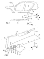
- Fig. 1 shows a side frame 3 of a self-supporting body 2 of a Motor vehicle 1.
- the side frame 3 is with door cutouts 4 and 5 for not provided doors provided. Following the rear door opening 5 is on the side frame 3, a rear wheel arch 6 is formed.
- a sill 10 is on the one hand spaced from a bottom portion 7 of the side frame 3 and the others at a lower end 9 of a vehicle longitudinal direction x, outer side portion 8 of the side frame 3 attached.
- a reinforcing element 12 fixed, which in the embodiment shown in one piece with a bottom component 13 of a floor covering or floor assembly of the body 2, not shown connected is.
- bottom member 13 On the bottom member 13 is in the embodiment shown in Figs. 1 and 5 another bottom member 14 arranged at its the rear wheel arch. 6 facing end 15 has a ram lip 16.
- the attachment of the Reinforcement element 12 with the sill 10, the bottom member 13 with the Floor component 14 and the bottom member 14 with the ram lip 16 is done for example via clip and / or screw 17.
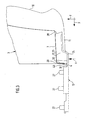
- Fig. 2 shows a the rear wheel arch 6 facing, rear end 18 of the Sill 10.
- the sill 10 is designed as an open profile with a side wall 19 and the bottom wall 11 is formed.
- the bottom wall 11 in the connection to the attached to the bottom wall 11 reinforcing member 12 has an opening or a cutout 20 through which a receptacle for a jack in assembled state of the body 2 is passed.
- the reinforcing element 12 is substantially cuboid with a in principle rectangular cross-section and a rectangular longitudinal section educated. To save weight, the reinforcing element 12 is not solid formed, but has a load optimized in the vehicle longitudinal direction x extending stiffening wall 21 and perpendicular thereto, in Vehicle transverse direction extending transverse reinforcing walls 22a to 22c on how this is apparent in particular from FIG. 5.
- the reinforcing element 12 is provided with a peripheral side edge 23, with the one piece, the longitudinal reinforcement wall 21 and the Querversteifungsclaim 22a to 22c are connected. Furthermore, the reinforcing element 12 is provided with a Floor 24 provided. Adjacent stiffening walls 21, 22, 23 can for Increasing the rigidity or training of mounting shots over a corresponding upper portion 25 to form a closed Cavity 32 to be closed. Between the stiffening walls 21, 22 and 23 can be provided upwardly open recesses 33. That with the Reinforcement member 12 integrally connected bottom member 13 is shown in the Embodiment designed as a flat plate on which as a nut or dowel serving fasteners 27 are provided.
- a downwardly extending flange 30 is formed, the by a distance a from a top 31 of the bottom 24 of the Reinforcement element 12 is spaced.
- the distance a marks the Distance by which the reinforcing element 12 maximally in the vertical direction z elastically deformed. Over the bottom 24, the reinforcing element 12 is in one piece connected to the bottom member 13.
- FIG. 4 shows a cross section which is in the vehicle transverse direction y as in FIG. 3 runs.
- an upwardly open cavity 33 can be seen.
- the open cavity 33 has a conically upwardly from a bottom 24 expanding cross-section on.
- FIG. 4 an upwardly closed cavity 32 is shown in FIG which is arranged as a sleeve 34 fastening device 27 is arranged, the is formed at its upper end 35 as an expandable dowel 36.
- a screw 37 is arranged in the sleeve 34 in the sleeve 34.
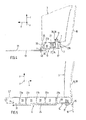
- Fig. 5 shows a rear end 38 of the reinforcing element 12, on which the Floor member 14 is attached via a screw 17 or the like.
- the bottom member 14 has the ram lip 16, which is an extension of a in Vehicle transverse direction y extending side wall 39 of the rear wheel arch 6 is and which serves, among other things, to deflect the airstream flow.
- Fig. 5 the vehicle transverse direction y extending outer walls 23a and the inner reinforcing transverse walls 22a to 22c shown.
- the by the Stiffening transverse walls 22a to 22c and the outer edges 23 open at the top Cavities 33 each have a conical cross section to the molding to simplify in the manufacture of the reinforcing element 12.
- a dotted line is a lower outer edge 40 of the flange 30 shown to a distance a from the top 31 of the bottom 24 is spaced.
- the shown has in principle a weight and load optimized Honeycomb structure on.
- the shape, size, rigidity of the reinforcing element 12 and the selection of a suitable material depends on the given spatial Conditions, the shape and rigidity of the side frame 3, in particular its Bottom section 7 and an optional flange 30, further from the shape and rigidity of the sill 10 and the bottom wall 11 and the from the outside via the bottom wall 11 einleitbaren force F from.
- the force F is from several parameters such as the vehicle weight, the maximum payload of the Vehicle and the distance of the sill 10 to the roadway affected.
- the reinforcing element 12 consists of a elastically deformable plastic.
- a suitable thermoplastic is suitable PPEPDM proved. In other embodiments, too Material combinations of plastic and metal can be used.
Landscapes
- Engineering & Computer Science (AREA)
- Chemical & Material Sciences (AREA)
- Combustion & Propulsion (AREA)
- Transportation (AREA)
- Mechanical Engineering (AREA)
- Body Structure For Vehicles (AREA)
Applications Claiming Priority (2)
| Application Number | Priority Date | Filing Date | Title |
|---|---|---|---|
| DE102004016137 | 2004-04-01 | ||
| DE200410016137 DE102004016137A1 (de) | 2004-04-01 | 2004-04-01 | Kraftfahrzeug |
Publications (3)
| Publication Number | Publication Date |
|---|---|
| EP1582441A2 true EP1582441A2 (fr) | 2005-10-05 |
| EP1582441A3 EP1582441A3 (fr) | 2006-04-12 |
| EP1582441B1 EP1582441B1 (fr) | 2007-11-07 |
Family
ID=34877695
Family Applications (1)
| Application Number | Title | Priority Date | Filing Date |
|---|---|---|---|
| EP20050006208 Expired - Lifetime EP1582441B1 (fr) | 2004-04-01 | 2005-03-22 | Longeron d'un carrosserie autoportant d'un véhicule automobile |
Country Status (3)
| Country | Link |
|---|---|
| EP (1) | EP1582441B1 (fr) |
| DE (2) | DE102004016137A1 (fr) |
| ES (1) | ES2293403T3 (fr) |
Cited By (1)
| Publication number | Priority date | Publication date | Assignee | Title |
|---|---|---|---|---|
| CN110194053A (zh) * | 2018-02-23 | 2019-09-03 | 丰田自动车株式会社 | 车辆下部构造 |
Families Citing this family (3)
| Publication number | Priority date | Publication date | Assignee | Title |
|---|---|---|---|---|
| DE102008057884B4 (de) | 2008-11-18 | 2019-02-07 | Audi Ag | Aufbaustruktur für eine Karosserie eines Fahrzeugs |
| DE102011106951A1 (de) * | 2011-07-08 | 2013-01-10 | GM Global Technology Operations LLC (n. d. Gesetzen des Staates Delaware) | Kraftfahrzeugkarosserie |
| DE202014000948U1 (de) * | 2014-01-31 | 2015-05-05 | GM Global Technology Operations LLC (n. d. Ges. d. Staates Delaware) | Verbindungselement zum Verbinden eines Anbauteils mit einer Fahrzeugkarosserie |
Citations (1)
| Publication number | Priority date | Publication date | Assignee | Title |
|---|---|---|---|---|
| DE19708215A1 (de) | 1997-02-28 | 1997-07-24 | Audi Ag | Schweller eines Kraftfahrzeugs mit einer Verstärkungseinlage |
Family Cites Families (3)
| Publication number | Priority date | Publication date | Assignee | Title |
|---|---|---|---|---|
| JPS58145576A (ja) * | 1982-02-22 | 1983-08-30 | Suzuki Motor Co Ltd | 自動車のアンダ−プロテクタ− |
| DE19528309C2 (de) * | 1995-08-02 | 1998-03-19 | Daimler Benz Ag | Selbsttragende Kraftfahrzeugkarosserie mit seitlichen Türschwellern |
| GB2324069B (en) * | 1997-04-12 | 2001-06-13 | Rover Group | A jacking point for a motor vehicle |
-
2004
- 2004-04-01 DE DE200410016137 patent/DE102004016137A1/de not_active Withdrawn
-
2005
- 2005-03-22 EP EP20050006208 patent/EP1582441B1/fr not_active Expired - Lifetime
- 2005-03-22 DE DE200550001853 patent/DE502005001853D1/de not_active Expired - Lifetime
- 2005-03-22 ES ES05006208T patent/ES2293403T3/es not_active Expired - Lifetime
Patent Citations (1)
| Publication number | Priority date | Publication date | Assignee | Title |
|---|---|---|---|---|
| DE19708215A1 (de) | 1997-02-28 | 1997-07-24 | Audi Ag | Schweller eines Kraftfahrzeugs mit einer Verstärkungseinlage |
Cited By (2)
| Publication number | Priority date | Publication date | Assignee | Title |
|---|---|---|---|---|
| CN110194053A (zh) * | 2018-02-23 | 2019-09-03 | 丰田自动车株式会社 | 车辆下部构造 |
| CN110194053B (zh) * | 2018-02-23 | 2022-03-08 | 丰田自动车株式会社 | 车辆下部构造 |
Also Published As
| Publication number | Publication date |
|---|---|
| ES2293403T3 (es) | 2008-03-16 |
| DE502005001853D1 (de) | 2007-12-20 |
| EP1582441B1 (fr) | 2007-11-07 |
| EP1582441A3 (fr) | 2006-04-12 |
| DE102004016137A1 (de) | 2005-11-03 |
Similar Documents
| Publication | Publication Date | Title |
|---|---|---|
| DE10206768B4 (de) | Kotflügelanordnung für ein Kraftfahrzeug | |
| DE19748970B4 (de) | Integrale Türinnenverstärkung | |
| EP1612127B1 (fr) | Véhicule automobile avec un coffre | |
| EP0454942A1 (fr) | Caisse de véhicule, en particulier pour voiture particulière | |
| DE202014002086U1 (de) | Bodenstruktur einer Kraftfahrzeugkarosserie in Leichtbauweise | |
| DE102011117682A1 (de) | Längsrahmen für die Unterbaustruktur eines Kraftfahrzeuges und Kraftfahrzeug-Unterbaustruktur | |
| DE102006014961A1 (de) | Deformationselement zur Aufnahme von Seitenaufprallkräften im Seitenbereich eines Kraftfahrzeuges | |
| EP1840006A1 (fr) | Structure de traverse pour une zone d'assise d'un véhicule automobile | |
| DE102007041382B4 (de) | Reserveradmulde für ein Kraftfahrzeug | |
| DE102004049034B4 (de) | Wasserkasten für einen Personenkraftwagen | |
| EP1319584B1 (fr) | Benne basculante pour un véhicule | |
| EP1534577A1 (fr) | Carrosserie de voiture avec montant | |
| DE102010049983B4 (de) | Trägerprofil für einen Dachquerträger eines Kraftfahrzeugs | |
| EP1084935A2 (fr) | Chassis auxiliaire d'un carrosserie de véhicule automobile pour absorber l'énergie de collision | |
| WO1995028295A1 (fr) | Portes de vehicule a systeme anticollision amovible | |
| EP1582441B1 (fr) | Longeron d'un carrosserie autoportant d'un véhicule automobile | |
| DE10302756B4 (de) | Tragstruktur für eine Kraftwagenkarosserie | |
| DE102015012262B4 (de) | Tür für einen Kraftwagen | |
| DE19710894A1 (de) | Wandstruktur | |
| DE102005011834B4 (de) | Seitlicher Dachrahmen für ein Kraftfahrzeug | |
| DE102010054688A1 (de) | Bodenstruktur für ein Kraftfahrzeug, Fahrzeugkarosserie und Kraftfahrzeug | |
| DE102005016994A1 (de) | Kraftfahrzeug mit einem Versteifungselement | |
| DE29900510U1 (de) | Trägerkonstruktion zur Befestigung eines Formteils an einer Fahrzeugkarosserie | |
| DE19805804A1 (de) | Fahrzeugkarosserie | |
| DE102004006406B4 (de) | Vordere Motorraumverkleidung eines Kraftfahrzeuges mit einer Fußgängeraufprallschutzfunktion |
Legal Events
| Date | Code | Title | Description |
|---|---|---|---|
| PUAI | Public reference made under article 153(3) epc to a published international application that has entered the european phase |
Free format text: ORIGINAL CODE: 0009012 |
|
| AK | Designated contracting states |
Kind code of ref document: A2 Designated state(s): AT BE BG CH CY CZ DE DK EE ES FI FR GB GR HU IE IS IT LI LT LU MC NL PL PT RO SE SI SK TR |
|
| AX | Request for extension of the european patent |
Extension state: AL BA HR LV MK YU |
|
| PUAL | Search report despatched |
Free format text: ORIGINAL CODE: 0009013 |
|
| AK | Designated contracting states |
Kind code of ref document: A3 Designated state(s): AT BE BG CH CY CZ DE DK EE ES FI FR GB GR HU IE IS IT LI LT LU MC NL PL PT RO SE SI SK TR |
|
| AX | Request for extension of the european patent |
Extension state: AL BA HR LV MK YU |
|
| 17P | Request for examination filed |
Effective date: 20060506 |
|
| AKX | Designation fees paid |
Designated state(s): DE ES FR GB IT |
|
| GRAP | Despatch of communication of intention to grant a patent |
Free format text: ORIGINAL CODE: EPIDOSNIGR1 |
|
| GRAS | Grant fee paid |
Free format text: ORIGINAL CODE: EPIDOSNIGR3 |
|
| GRAA | (expected) grant |
Free format text: ORIGINAL CODE: 0009210 |
|
| AK | Designated contracting states |
Kind code of ref document: B1 Designated state(s): DE ES FR GB IT |
|
| REG | Reference to a national code |
Ref country code: GB Ref legal event code: FG4D Free format text: NOT ENGLISH |
|
| REF | Corresponds to: |
Ref document number: 502005001853 Country of ref document: DE Date of ref document: 20071220 Kind code of ref document: P |
|
| REG | Reference to a national code |
Ref country code: ES Ref legal event code: FG2A Ref document number: 2293403 Country of ref document: ES Kind code of ref document: T3 |
|
| ET | Fr: translation filed | ||
| PLBE | No opposition filed within time limit |
Free format text: ORIGINAL CODE: 0009261 |
|
| STAA | Information on the status of an ep patent application or granted ep patent |
Free format text: STATUS: NO OPPOSITION FILED WITHIN TIME LIMIT |
|
| 26N | No opposition filed |
Effective date: 20080808 |
|
| REG | Reference to a national code |
Ref country code: FR Ref legal event code: PLFP Year of fee payment: 12 |
|
| REG | Reference to a national code |
Ref country code: FR Ref legal event code: PLFP Year of fee payment: 13 |
|
| REG | Reference to a national code |
Ref country code: FR Ref legal event code: PLFP Year of fee payment: 14 |
|
| PGFP | Annual fee paid to national office [announced via postgrant information from national office to epo] |
Ref country code: DE Payment date: 20190321 Year of fee payment: 15 Ref country code: GB Payment date: 20190325 Year of fee payment: 15 Ref country code: FR Payment date: 20190326 Year of fee payment: 15 Ref country code: IT Payment date: 20190321 Year of fee payment: 15 |
|
| PGFP | Annual fee paid to national office [announced via postgrant information from national office to epo] |
Ref country code: ES Payment date: 20190424 Year of fee payment: 15 |
|
| REG | Reference to a national code |
Ref country code: DE Ref legal event code: R119 Ref document number: 502005001853 Country of ref document: DE |
|
| PG25 | Lapsed in a contracting state [announced via postgrant information from national office to epo] |
Ref country code: DE Free format text: LAPSE BECAUSE OF NON-PAYMENT OF DUE FEES Effective date: 20201001 Ref country code: FR Free format text: LAPSE BECAUSE OF NON-PAYMENT OF DUE FEES Effective date: 20200331 |
|
| GBPC | Gb: european patent ceased through non-payment of renewal fee |
Effective date: 20200322 |
|
| PG25 | Lapsed in a contracting state [announced via postgrant information from national office to epo] |
Ref country code: GB Free format text: LAPSE BECAUSE OF NON-PAYMENT OF DUE FEES Effective date: 20200322 |
|
| REG | Reference to a national code |
Ref country code: ES Ref legal event code: FD2A Effective date: 20210804 |
|
| PG25 | Lapsed in a contracting state [announced via postgrant information from national office to epo] |
Ref country code: IT Free format text: LAPSE BECAUSE OF NON-PAYMENT OF DUE FEES Effective date: 20200322 |
|
| PG25 | Lapsed in a contracting state [announced via postgrant information from national office to epo] |
Ref country code: ES Free format text: LAPSE BECAUSE OF NON-PAYMENT OF DUE FEES Effective date: 20200323 |
|
| P01 | Opt-out of the competence of the unified patent court (upc) registered |
Effective date: 20230503 |