EP1582443A2 - Dispositif de basculement pour cabines suspendues disposé sur le châssis d'un camion - Google Patents
Dispositif de basculement pour cabines suspendues disposé sur le châssis d'un camion Download PDFInfo
- Publication number
- EP1582443A2 EP1582443A2 EP05005687A EP05005687A EP1582443A2 EP 1582443 A2 EP1582443 A2 EP 1582443A2 EP 05005687 A EP05005687 A EP 05005687A EP 05005687 A EP05005687 A EP 05005687A EP 1582443 A2 EP1582443 A2 EP 1582443A2
- Authority
- EP
- European Patent Office
- Prior art keywords
- engagement
- cab
- piston rod
- tilting
- opening
- Prior art date
- Legal status (The legal status is an assumption and is not a legal conclusion. Google has not performed a legal analysis and makes no representation as to the accuracy of the status listed.)
- Granted
Links
Images



Classifications
-
- B—PERFORMING OPERATIONS; TRANSPORTING
- B62—LAND VEHICLES FOR TRAVELLING OTHERWISE THAN ON RAILS
- B62D—MOTOR VEHICLES; TRAILERS
- B62D33/00—Superstructures for load-carrying vehicles
- B62D33/06—Drivers' cabs
- B62D33/063—Drivers' cabs movable from one position into at least one other position, e.g. tiltable, pivotable about a vertical axis, displaceable from one side of the vehicle to the other
- B62D33/067—Drivers' cabs movable from one position into at least one other position, e.g. tiltable, pivotable about a vertical axis, displaceable from one side of the vehicle to the other tiltable
- B62D33/07—Drivers' cabs movable from one position into at least one other position, e.g. tiltable, pivotable about a vertical axis, displaceable from one side of the vehicle to the other tiltable characterised by the device for locking the cab in the tilted or in the driving position
Definitions
- the invention relates to a device for tilting a vehicle frame of a commercial vehicle sprung cab opposite the vehicle frame after the generic term of claim 1.
- From DE 198 05 870 A1 is such a device for tilting a vehicle frame sprung cab known in a commercial vehicle.
- the known device includes a hydraulically actuated tipping cylinder with which a pivotable on the vehicle frame stored hook-shaped engagement part with a second attached to the cab Engaging part in the form of a bolt extending transversely to the hook opening during tilting in Intervention is brought.
- the two engaging parts are in separate rest positions.
- the tilted state of the cab that is Locked on the cab engaging part not locked in all directions.
- the Bolts along the opening of the hook-shaped engagement part with the possibility of unlocking can move.
- the object of the invention is to provide a device of the type mentioned in at which the cab in the tilted position in all directions of movement, in particular against a Zuschverschwenken, with simple means locked.
- the two engagement parts, the first and second engagement part at least moved at the end of the tilting in such a position in which due to the shape the engagement surfaces with which the engagement members in this position abut, in All three spatial directions locking the tilted cab is achieved.
- the first engagement member moved by the tilt cylinder is preferably rectilinear moving in a certain direction.
- the second Engagement part which is fixed to the cab, preferably a hollow guttered recess has, so that the first engagement part through the opening of the second Can move engagement part to the engaged position.
- the two engagement parts rotate against each other, so that during the Tilting and especially at the end of the tilting the adjacent Engagement surfaces of the two engagement parts acting in all three spatial directions locking produce. In this way it is ensured that even with a shock-like load, Which, for example, in a collision on the stationary commercial vehicle with The tilted cab can arise, a secure locking in all degrees of freedom is reached.
- the lifting element which is preferably a hydraulically actuated tilting cylinder, can be designed as protruding from the cylinder piston rod.
- the first engagement part is attached.
- the dimensions of the opening provided in the second engagement part are in the engaged position "spherical" executed. In this position, the first and the second engagement part against each other pivotable, wherein the required pivotability of said engagement parts must be ensured in the tilting of the cab. Due to the crowned design of said second engagement part, it is necessary, this part in two parts for manufacturing reasons manufacture.
- the second engagement part therefore has a larger diameter as the first engaging part formed on the piston rod.
- the to the Slot subsequent engagement surfaces in the hollow or spherical recess of the second engagement part are so on the engagement surfaces of the inserted first engagement part in that a release of the two engagement parts from the engagement position in each direction of movement of the tilted cab is prevented.
- a cab 11 is shown schematically, which by means of not closer illustrated springs in a known manner on a vehicle frame shown schematically 10 of a commercial vehicle is cushioned.
- a tilting device for tilting the cab 11 in their rest positions.
- These components include a tilt cylinder 12, which preferably operates hydraulically becomes.
- the tilt cylinder 12 is at an attachment point 28 on the vehicle frame 10th supported. From the tilting cylinder 12 protrudes a linearly driven lifting element 13 in the form a piston rod.
- the first engagement part 14 may have a cylindrical outer surface. At both ends are each a spherical cap-shaped engagement surface 22 and the rear end also a spherical engagement surface 20 which of the piston rod 13 in the middle is provided, provided (Fig. 5).
- the second engagement part 15 is attached, which is in perspective view in Fig. 4 is shown.
- the engagement member 15 has an opening 17, to which a slot 18 connects.
- the engagement part 15 has a hollow or spherical recess 25, in which the engaging member 14 through the opening 17 for a locking engagement can be inserted during tilting.
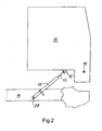
- the piston rod 13 is first rectilinear in a certain direction from the in the position shown in FIG. 2 through the opening 17 in FIG the hollow or spherical recess 25 of the second engaging part 15 is inserted.
- the Opening 17 on the second engaging part 15 is for this purpose to the rectilinear movement direction of the piston rod 13 mounted first engagement member 14 aligned.
- the dimensions of the Opening 17, the second engaging part which surrounded by boundary edges 23 and 24 is dimensioned slightly larger than the dimensions of the first engaging part 14, so that this through the opening 17 in the hollow or spherical recess 25 of the second Engaging part can be inserted.
- the front is spherical Engagement surface 22 of the first engagement part 14 on an engagement surface 21 of the second engagement part, which is designed as a spherical partial cavity in the recess 25 at.
- This spherical segment-shaped Engagement surface 21 is located on both sides of the slot 18, which adjoins the opening 17, continues in the recess and forms on both sides of the Slot 18 engagement surfaces 19.
- the spherical part of the first engagement part 14 has a larger diameter as the width of the slot 18, is the rear spherical engagement surface 20 of the first Engagement part 14 on the engagement surfaces 19 of the recess 25 on both sides of the slot 18 of the second engaging part, as shown in Fig. 5.
- the distance between the both boundary edges 23 at the bottom of the opening 17 opposite the top is less than the entire axial length of the Engagement part 14, as shown in FIG. 5 can be seen. This ensures that the engagement part 14 in the tilted position of the cab 11 neither through the opening 17 yet through the slot 18 can move out of the recess 25 in the engaging part 15.
- the Engagement member 14 is in all three spatial directions in the recess 25 of the engagement member 15th locked. In this case, the two parts of the engagement part 15, which on both sides of the slot 18, the claw-shaped engagement member 14th
- Fig. 4 is the visible boundary line 26 is shown.
- the spherical engagement surfaces 20, 22 and the spherical segment surface shown in the embodiment 21 on the engagement parts 14, 15 are preferred embodiments. It is however, also possible, these engagement surfaces circular cylindrical with parallel to the pivot axis Form 16 extending cylinder axes. This would then have to the piston rod 13th and transverse to the longitudinal center line of the piston rod 13, a cylindrical bolt with the corresponding Dimensions are fixed instead of the engaging member 14
- the direction of movement is by exact To ensure positioning of the tilt cylinder 12.
- the tilting cylinder 12th a fixed to the vehicle frame 10 of the utility vehicle fixing device 27 is provided be.
- the subsequent tilting of the tilting cylinder 12 for a Pivoting movement in the attachment point 28 are released from the fixing device 27 or stay fixed.
- the second engaging member 15 is located with the opening 17 on the cab 11 and the first engaging part 14 on the piston rod 13. It is also possible to reverse the arrangement of the engaging parts, so that with the opening 17th and the hollow groove 25 provided second engaging part 15 at the front end the piston rod 13 and the first engagement part 14 is fixed to the cab 11.
Landscapes
- Engineering & Computer Science (AREA)
- Chemical & Material Sciences (AREA)
- Combustion & Propulsion (AREA)
- Transportation (AREA)
- Mechanical Engineering (AREA)
- Body Structure For Vehicles (AREA)
- Actuator (AREA)
- Fluid-Damping Devices (AREA)
Applications Claiming Priority (2)
| Application Number | Priority Date | Filing Date | Title |
|---|---|---|---|
| DE200410015351 DE102004015351A1 (de) | 2004-03-30 | 2004-03-30 | Vorrichtung zum Kippen eines am Fahrzeugrahmen eines Nutzfahrzeugs abgefederten Fahrerhauses |
| DE102004015351 | 2004-03-30 |
Publications (3)
| Publication Number | Publication Date |
|---|---|
| EP1582443A2 true EP1582443A2 (fr) | 2005-10-05 |
| EP1582443A3 EP1582443A3 (fr) | 2006-02-01 |
| EP1582443B1 EP1582443B1 (fr) | 2009-09-09 |
Family
ID=34877645
Family Applications (1)
| Application Number | Title | Priority Date | Filing Date |
|---|---|---|---|
| EP05005687A Expired - Lifetime EP1582443B1 (fr) | 2004-03-30 | 2005-03-16 | Dispositif de basculement pour cabines suspendues disposé sur le châssis d'un camion |
Country Status (2)
| Country | Link |
|---|---|
| EP (1) | EP1582443B1 (fr) |
| DE (2) | DE102004015351A1 (fr) |
Cited By (2)
| Publication number | Priority date | Publication date | Assignee | Title |
|---|---|---|---|---|
| WO2007136341A1 (fr) * | 2006-05-19 | 2007-11-29 | Scania Cv Ab (Publ) | Dispositif de cabine basculante |
| EP2060475A4 (fr) * | 2006-10-25 | 2011-01-05 | Yanmar Co Ltd | Véhicule de travaux équipé d'une cabine |
Citations (4)
| Publication number | Priority date | Publication date | Assignee | Title |
|---|---|---|---|---|
| JPS58128974A (ja) | 1982-01-27 | 1983-08-01 | Hino Motors Ltd | キヤブのチルト装置 |
| DE3314404A1 (de) | 1982-08-19 | 1984-02-23 | Sanwa Seiki Mfg. Co., Ltd., Yono, Saitama | Fahrkabinen-kippsystem |
| EP0149810B1 (fr) | 1984-01-21 | 1987-03-11 | MAN Nutzfahrzeuge Aktiengesellschaft | Dispositif de commande pour la suspension élastique d'une cabine d'un camion |
| DE19805870A1 (de) | 1998-02-13 | 1999-08-26 | Daimler Chrysler Ag | Kippvorrichtung für abgefederte Fahrerhäuser von Nutzfahrzeugen |
Family Cites Families (4)
| Publication number | Priority date | Publication date | Assignee | Title |
|---|---|---|---|---|
| US2939541A (en) * | 1958-07-14 | 1960-06-07 | Int Harvester Co | Mounting and lock means for a forwardly tilting motor vehicle cab |
| JPS5897569A (ja) * | 1981-12-01 | 1983-06-10 | Mitsuwa Seiki Co Ltd | 運転台持上装置 |
| DE8809201U1 (de) * | 1988-07-19 | 1988-09-01 | Iveco Magirus AG, 7900 Ulm | Kippvorrichtung für das kippbare gefederte Fahrerhaus eines Nutzfahrzeuges |
| NL9101118A (nl) * | 1991-06-27 | 1993-01-18 | Applied Power Inc | Kantelinrichting voor een voertuig met kantelcabine. |
-
2004
- 2004-03-30 DE DE200410015351 patent/DE102004015351A1/de not_active Withdrawn
-
2005
- 2005-03-16 EP EP05005687A patent/EP1582443B1/fr not_active Expired - Lifetime
- 2005-03-16 DE DE200550008080 patent/DE502005008080D1/de not_active Expired - Lifetime
Patent Citations (4)
| Publication number | Priority date | Publication date | Assignee | Title |
|---|---|---|---|---|
| JPS58128974A (ja) | 1982-01-27 | 1983-08-01 | Hino Motors Ltd | キヤブのチルト装置 |
| DE3314404A1 (de) | 1982-08-19 | 1984-02-23 | Sanwa Seiki Mfg. Co., Ltd., Yono, Saitama | Fahrkabinen-kippsystem |
| EP0149810B1 (fr) | 1984-01-21 | 1987-03-11 | MAN Nutzfahrzeuge Aktiengesellschaft | Dispositif de commande pour la suspension élastique d'une cabine d'un camion |
| DE19805870A1 (de) | 1998-02-13 | 1999-08-26 | Daimler Chrysler Ag | Kippvorrichtung für abgefederte Fahrerhäuser von Nutzfahrzeugen |
Cited By (3)
| Publication number | Priority date | Publication date | Assignee | Title |
|---|---|---|---|---|
| WO2007136341A1 (fr) * | 2006-05-19 | 2007-11-29 | Scania Cv Ab (Publ) | Dispositif de cabine basculante |
| EP2060475A4 (fr) * | 2006-10-25 | 2011-01-05 | Yanmar Co Ltd | Véhicule de travaux équipé d'une cabine |
| US8157042B2 (en) | 2006-10-25 | 2012-04-17 | Yanmar Co., Ltd | Working vehicle with cabin |
Also Published As
| Publication number | Publication date |
|---|---|
| DE102004015351A1 (de) | 2005-10-20 |
| EP1582443B1 (fr) | 2009-09-09 |
| EP1582443A3 (fr) | 2006-02-01 |
| DE502005008080D1 (de) | 2009-10-22 |
Similar Documents
| Publication | Publication Date | Title |
|---|---|---|
| DE69600483T2 (de) | Dachgepäckträger für kraftfahrzeuge | |
| EP0752344B1 (fr) | Arceau de sécurité télescopique | |
| EP1145919A2 (fr) | Dispositif de sécurité pour le conducteur d'un véhicule, en particulier de manutention | |
| DE69501940T2 (de) | Abnehmbare Befestigung eines Fahrzeugsitzuntergestells auf einem Boden | |
| DE10261538A1 (de) | Lenksäule | |
| DE19740776C1 (de) | Umklappbare Rückenlehne für eine Sitzbank | |
| DE4315017C1 (de) | Haltevorrichtung für am Fahrzeugrahmen kippbar gelagerte Fahrerhäuser von Lastkraftwagen | |
| EP2053010B1 (fr) | Dispositif de verrouillage | |
| EP1544003B1 (fr) | Dispositif d'attelage pour véhicules automobiles | |
| DE102019200488A1 (de) | Lenksäule für ein Kraftfahrzeug | |
| EP3691958A1 (fr) | Dispositif de basculement pour la cabine d'un poids lourd | |
| EP1582443A2 (fr) | Dispositif de basculement pour cabines suspendues disposé sur le châssis d'un camion | |
| DE3340344C2 (fr) | ||
| DE19937698A1 (de) | Schaltvorrichtung eines automatischen Kraftfahrzeuggetriebes | |
| DE60003166T2 (de) | Kippvorrichtung | |
| DE10034019B4 (de) | Befestigungsvorrichtung, insbesondere für einen Fahrzeugsitz | |
| DE202007006419U1 (de) | Seitenrunge für einen Nutzfahrzeugaufbau | |
| EP1076147A2 (fr) | Dispositif déflecteur pour panneau basculant ou oscillo-battant monté pivotant sur un cadre et panneau basculant ou oscillo-battant avec dispositif déflecteur | |
| EP0384005B1 (fr) | Dispositif de basculement de cabines de conducteurs de camions | |
| DE2900514C2 (fr) | ||
| EP3868636A1 (fr) | Trottinette | |
| EP0333066A1 (fr) | Engin de terrassement, notamment un chargeur | |
| DE19719216C2 (de) | Crash-Verriegelung | |
| DE69919570T2 (de) | Befestigungsvorrichtung eines abnehmbaren sitzes an einem kraftfahrzeugboden | |
| DE69204758T2 (de) | Runge für eine Ladefläche und Methode zum Montieren einer Schliess- und Beeinflussungsvorrichtung in dieser. |
Legal Events
| Date | Code | Title | Description |
|---|---|---|---|
| PUAI | Public reference made under article 153(3) epc to a published international application that has entered the european phase |
Free format text: ORIGINAL CODE: 0009012 |
|
| AK | Designated contracting states |
Kind code of ref document: A2 Designated state(s): AT BE BG CH CY CZ DE DK EE ES FI FR GB GR HU IE IS IT LI LT LU MC NL PL PT RO SE SI SK TR |
|
| AX | Request for extension of the european patent |
Extension state: AL BA HR LV MK YU |
|
| PUAL | Search report despatched |
Free format text: ORIGINAL CODE: 0009013 |
|
| AK | Designated contracting states |
Kind code of ref document: A3 Designated state(s): AT BE BG CH CY CZ DE DK EE ES FI FR GB GR HU IE IS IT LI LT LU MC NL PL PT RO SE SI SK TR |
|
| AX | Request for extension of the european patent |
Extension state: AL BA HR LV MK YU |
|
| 17P | Request for examination filed |
Effective date: 20060215 |
|
| AKX | Designation fees paid |
Designated state(s): DE FR IT NL SE |
|
| GRAP | Despatch of communication of intention to grant a patent |
Free format text: ORIGINAL CODE: EPIDOSNIGR1 |
|
| GRAS | Grant fee paid |
Free format text: ORIGINAL CODE: EPIDOSNIGR3 |
|
| GRAA | (expected) grant |
Free format text: ORIGINAL CODE: 0009210 |
|
| AK | Designated contracting states |
Kind code of ref document: B1 Designated state(s): DE FR IT NL SE |
|
| REF | Corresponds to: |
Ref document number: 502005008080 Country of ref document: DE Date of ref document: 20091022 Kind code of ref document: P |
|
| REG | Reference to a national code |
Ref country code: SE Ref legal event code: TRGR |
|
| PLBE | No opposition filed within time limit |
Free format text: ORIGINAL CODE: 0009261 |
|
| STAA | Information on the status of an ep patent application or granted ep patent |
Free format text: STATUS: NO OPPOSITION FILED WITHIN TIME LIMIT |
|
| 26N | No opposition filed |
Effective date: 20100610 |
|
| REG | Reference to a national code |
Ref country code: NL Ref legal event code: TD Effective date: 20110420 |
|
| REG | Reference to a national code |
Ref country code: FR Ref legal event code: CD |
|
| REG | Reference to a national code |
Ref country code: DE Ref legal event code: R081 Ref document number: 502005008080 Country of ref document: DE Owner name: MAN TRUCK & BUS AG, DE Free format text: FORMER OWNER: MAN NUTZFAHRZEUGE AKTIENGESELLSCHAFT, 80995 MUENCHEN, DE Effective date: 20110518 |
|
| REG | Reference to a national code |
Ref country code: FR Ref legal event code: PLFP Year of fee payment: 12 |
|
| PG25 | Lapsed in a contracting state [announced via postgrant information from national office to epo] |
Ref country code: IT Free format text: LAPSE BECAUSE OF NON-PAYMENT OF DUE FEES Effective date: 20160316 |
|
| REG | Reference to a national code |
Ref country code: FR Ref legal event code: PLFP Year of fee payment: 13 |
|
| PG25 | Lapsed in a contracting state [announced via postgrant information from national office to epo] |
Ref country code: IT Free format text: LAPSE BECAUSE OF NON-PAYMENT OF DUE FEES Effective date: 20160316 |
|
| PGRI | Patent reinstated in contracting state [announced from national office to epo] |
Ref country code: IT Effective date: 20170710 |
|
| REG | Reference to a national code |
Ref country code: FR Ref legal event code: PLFP Year of fee payment: 14 |
|
| REG | Reference to a national code |
Ref country code: DE Ref legal event code: R081 Ref document number: 502005008080 Country of ref document: DE Owner name: MAN TRUCK & BUS SE, DE Free format text: FORMER OWNER: MAN TRUCK & BUS AG, 80995 MUENCHEN, DE |
|
| PGFP | Annual fee paid to national office [announced via postgrant information from national office to epo] |
Ref country code: FR Payment date: 20230323 Year of fee payment: 19 |
|
| PGFP | Annual fee paid to national office [announced via postgrant information from national office to epo] |
Ref country code: SE Payment date: 20230317 Year of fee payment: 19 Ref country code: IT Payment date: 20230321 Year of fee payment: 19 Ref country code: DE Payment date: 20230328 Year of fee payment: 19 |
|
| PGFP | Annual fee paid to national office [announced via postgrant information from national office to epo] |
Ref country code: NL Payment date: 20230323 Year of fee payment: 19 |
|
| REG | Reference to a national code |
Ref country code: DE Ref legal event code: R119 Ref document number: 502005008080 Country of ref document: DE |
|
| REG | Reference to a national code |
Ref country code: SE Ref legal event code: EUG |
|
| REG | Reference to a national code |
Ref country code: NL Ref legal event code: MM Effective date: 20240401 |
|
| PG25 | Lapsed in a contracting state [announced via postgrant information from national office to epo] |
Ref country code: NL Free format text: LAPSE BECAUSE OF NON-PAYMENT OF DUE FEES Effective date: 20240401 |
|
| PG25 | Lapsed in a contracting state [announced via postgrant information from national office to epo] |
Ref country code: NL Free format text: LAPSE BECAUSE OF NON-PAYMENT OF DUE FEES Effective date: 20240401 |
|
| PG25 | Lapsed in a contracting state [announced via postgrant information from national office to epo] |
Ref country code: DE Free format text: LAPSE BECAUSE OF NON-PAYMENT OF DUE FEES Effective date: 20241001 |
|
| PG25 | Lapsed in a contracting state [announced via postgrant information from national office to epo] |
Ref country code: FR Free format text: LAPSE BECAUSE OF NON-PAYMENT OF DUE FEES Effective date: 20240331 |
|
| PG25 | Lapsed in a contracting state [announced via postgrant information from national office to epo] |
Ref country code: FR Free format text: LAPSE BECAUSE OF NON-PAYMENT OF DUE FEES Effective date: 20240331 Ref country code: DE Free format text: LAPSE BECAUSE OF NON-PAYMENT OF DUE FEES Effective date: 20241001 |
|
| PG25 | Lapsed in a contracting state [announced via postgrant information from national office to epo] |
Ref country code: SE Free format text: LAPSE BECAUSE OF NON-PAYMENT OF DUE FEES Effective date: 20240317 |