EP1582631A1 - Vorrichtung um die Strömung eines Durchflussmediums zu sperren oder zu regeln - Google Patents
Vorrichtung um die Strömung eines Durchflussmediums zu sperren oder zu regeln Download PDFInfo
- Publication number
- EP1582631A1 EP1582631A1 EP04076062A EP04076062A EP1582631A1 EP 1582631 A1 EP1582631 A1 EP 1582631A1 EP 04076062 A EP04076062 A EP 04076062A EP 04076062 A EP04076062 A EP 04076062A EP 1582631 A1 EP1582631 A1 EP 1582631A1
- Authority
- EP
- European Patent Office
- Prior art keywords
- sliding plate
- longitudinal edges
- mounting plate
- shaped
- plate
- Prior art date
- Legal status (The legal status is an assumption and is not a legal conclusion. Google has not performed a legal analysis and makes no representation as to the accuracy of the status listed.)
- Granted
Links
- 230000001105 regulatory effect Effects 0.000 title claims abstract description 8
- 230000007246 mechanism Effects 0.000 claims abstract description 12
- 208000007101 Muscle Cramp Diseases 0.000 claims 1
- 238000007789 sealing Methods 0.000 description 3
- XLYOFNOQVPJJNP-UHFFFAOYSA-N water Substances O XLYOFNOQVPJJNP-UHFFFAOYSA-N 0.000 description 2
- 229910000831 Steel Inorganic materials 0.000 description 1
- 238000010276 construction Methods 0.000 description 1
- 230000001419 dependent effect Effects 0.000 description 1
- 229920001971 elastomer Polymers 0.000 description 1
- 230000002349 favourable effect Effects 0.000 description 1
- -1 for instance Substances 0.000 description 1
- 238000012986 modification Methods 0.000 description 1
- 230000004048 modification Effects 0.000 description 1
- 239000004033 plastic Substances 0.000 description 1
- 239000005060 rubber Substances 0.000 description 1
- 229910001220 stainless steel Inorganic materials 0.000 description 1
- 239000010935 stainless steel Substances 0.000 description 1
- 239000010959 steel Substances 0.000 description 1
- 238000005728 strengthening Methods 0.000 description 1
- 239000000126 substance Substances 0.000 description 1
- 238000003466 welding Methods 0.000 description 1
Images




Classifications
-
- F—MECHANICAL ENGINEERING; LIGHTING; HEATING; WEAPONS; BLASTING
- F16—ENGINEERING ELEMENTS AND UNITS; GENERAL MEASURES FOR PRODUCING AND MAINTAINING EFFECTIVE FUNCTIONING OF MACHINES OR INSTALLATIONS; THERMAL INSULATION IN GENERAL
- F16K—VALVES; TAPS; COCKS; ACTUATING-FLOATS; DEVICES FOR VENTING OR AERATING
- F16K3/00—Gate valves or sliding valves, i.e. cut-off apparatus with closing members having a sliding movement along the seat for opening and closing
- F16K3/02—Gate valves or sliding valves, i.e. cut-off apparatus with closing members having a sliding movement along the seat for opening and closing with flat sealing faces; Packings therefor
- F16K3/0218—Gate valves or sliding valves, i.e. cut-off apparatus with closing members having a sliding movement along the seat for opening and closing with flat sealing faces; Packings therefor with only one sealing face
-
- E—FIXED CONSTRUCTIONS
- E02—HYDRAULIC ENGINEERING; FOUNDATIONS; SOIL SHIFTING
- E02B—HYDRAULIC ENGINEERING
- E02B7/00—Barrages or weirs; Layout, construction, methods of, or devices for, making same
- E02B7/20—Movable barrages; Lock or dry-dock gates
- E02B7/26—Vertical-lift gates
- E02B7/28—Vertical-lift gates with sliding gates
-
- E—FIXED CONSTRUCTIONS
- E02—HYDRAULIC ENGINEERING; FOUNDATIONS; SOIL SHIFTING
- E02B—HYDRAULIC ENGINEERING
- E02B8/00—Details of barrages or weirs ; Energy dissipating devices carried by lock or dry-dock gates
- E02B8/04—Valves, slides, or the like; Arrangements therefor; Submerged sluice gates
-
- F—MECHANICAL ENGINEERING; LIGHTING; HEATING; WEAPONS; BLASTING
- F16—ENGINEERING ELEMENTS AND UNITS; GENERAL MEASURES FOR PRODUCING AND MAINTAINING EFFECTIVE FUNCTIONING OF MACHINES OR INSTALLATIONS; THERMAL INSULATION IN GENERAL
- F16K—VALVES; TAPS; COCKS; ACTUATING-FLOATS; DEVICES FOR VENTING OR AERATING
- F16K3/00—Gate valves or sliding valves, i.e. cut-off apparatus with closing members having a sliding movement along the seat for opening and closing
- F16K3/30—Details
- F16K3/312—Line blinds
-
- F—MECHANICAL ENGINEERING; LIGHTING; HEATING; WEAPONS; BLASTING
- F16—ENGINEERING ELEMENTS AND UNITS; GENERAL MEASURES FOR PRODUCING AND MAINTAINING EFFECTIVE FUNCTIONING OF MACHINES OR INSTALLATIONS; THERMAL INSULATION IN GENERAL
- F16K—VALVES; TAPS; COCKS; ACTUATING-FLOATS; DEVICES FOR VENTING OR AERATING
- F16K3/00—Gate valves or sliding valves, i.e. cut-off apparatus with closing members having a sliding movement along the seat for opening and closing
- F16K3/30—Details
- F16K3/316—Guiding of the slide
Definitions
- the invention relates to a device for shutting off or regulating a medium flow, such as, for instance, a shutoff or an overflow slide, provided with a sliding plate which is movably set up and which is connected with an adjusting mechanism by means of which the sliding plate can be brought in different positions.
- Such a device is known from practice in the design of a shutoff and an overflow slide and is provided with costly guides to guide the sliding plate when setting it in different positions, for instance when setting it from the open position into a closed position and vice versa.
- These guides are to be mounted on the wall which includes the passage opening that is to be closed or cleared, or regulated, by means of the shutoff or overflow slide.
- the pressure that is exerted by the water or like medium on the sliding plate is relatively low, a much simpler and hence much less costly construction of the device could suffice.
- the object of the invention is to provide such a much less costly device, which moreover is readily mountable.
- the device of the type described in the opening paragraph hereof is characterized according to the invention in that it is provided with a mounting plate in which a passage opening is provided, of which passage opening the passage area can be shut off or regulated with the sliding plate, while the mounting plate further serves for guiding the sliding plate, and to that end the sliding plate is U-shaped at two opposite, first longitudinal edges (2a, 2a'), with the two U-shaped parts embracing the corresponding longitudinal edges (7a, 7a') of the mounting plate (7).
- the mounting plate constitutes the guide of the sliding plate
- the main parts of a device are provided in a very efficient manner with just two relatively inexpensive parts.
- the U-shaped longitudinal edges impart strength to the sliding plate which, incidentally, can be formed from a simple plate.
- the U-shaped parts are formed with the aid of a flanging operation.
- the U-shaped parts can also be formed in a manner other than through a flanging operation.
- the U-shaped edges can, for instance, be provided by fastening a U-section adjacent the edges of the plate.
- the other two opposed, second longitudinal edges of the sliding plate are U-shaped, with the U-shaped parts of the first longitudinal edges being situated on a first main side of the sliding plate and the U-shaped parts of the second longitudinal edges being situated on a second main side of the sliding plate, opposite the first main side.
- one of the U-shaped second longitudinal edges can serve for mounting the adjusting mechanism thereon, which adjusting mechanism has another end connected with the fixed world.
- the shutoff 1 represented in Fig. 1 is provided with a sliding plate 2 which is movably arranged. The movement is realized by means of an adjusting mechanism which comprises a spindle 3, a spindle nut 4 and a bearing block 5, with the spindle nut 4 being mounted on an upper edge 2b of the sliding plate 2.
- the shutoff 1 is further provided with a mounting plate 7 in which a passage opening 8 is provided (see Fig. 4). The passage opening 8 is closed off when the sliding plate 2 is in the closed position and cleared when the sliding plate 2 is in the open position.
- the mounting plate 7 further serves for guiding the sliding plate 2.
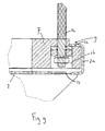
- the sliding plate 2 has been flanged on two opposite first longitudinal edges 2a, 2a' in the direction of a first main side of the sliding plate 2 to form a U-shape, which is clearly visible in the top plan view of Fig. 3.
- the two U-shaped, first longitudinal edges 2a, 2a' embrace the corresponding longitudinal edges 7a, 7a' of the mounting plate 7.
- the mounting plate 7 is provided with a recess 9, 9', which extends throughout the longitudinal edge of the mounting plate 7, such that a free leg of the U-shaped, first longitudinal edges 2a, 2a' of the sliding plate 2 are slidably receivable in the respective recesses.
- the mounting plate 7 is preferably made of plastic, which is of particular advantage from the viewpoint of costs.
- the sliding plate 2 is preferably manufactured from steel, such as, for instance, stainless steel.
- Fig. 4 shows a cross sectional view along line IV-IV from Fig. 2.
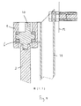
- the detail 2 which is represented in Fig. 6 shows in what way the screw spindle 3 is connected with the sliding plate 2 via the spindle nut 4.
- the spindle nut 4 will move up or down along the spindle 3.
- the sliding plate 2 will move up or down, respectively, while being guided over the mounting plate 7.
- the operating head 10 is connected with the fixed world by means of a bearing block support 6.
- the bearing block support 6 is also connected, by means of connecting rod 15, with the mounting plate, which has as a consequence that the bearing block support 6 only needs to be connected to the wall with a single bolt.
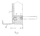
- FIG. 7 The detail 3 from Fig. 4 which is represented in Fig. 7 shows that in the mounting plate 7 two sealing rubbers 11, 12 are provided for providing, respectively, a sealing 11 between the mounting plate 7 and the wall M, and a sealing 12 between the mounting plate 7 and the sliding plate 2.
- Figs. 1 and 2 show that in the sliding plate 2 four holes 13 are provided at the corners. In a closed position of the sliding plate 2, the holes 13 are in line with four holes in the mounting plate 7 for mounting the mounting plate 7 on a wall M. Accordingly, the shutoff 1 can be transported to its destination site in virtually completely assembled condition and there be mounted on the wall M in a very simple manner.
- the sliding plate 2 only needs to be set in the closed condition; in the wall, four holes, if not present already, need to be provided, and subsequently the shutoff can be connected to the wall by means of four bolts or chemical anchors.
- the bearing block support 6 needs to be attached to the wall and the shutoff 1 is ready for use.
- the connection between the mounting plate 7 and the wall is clearly represented in Figs.
- the longitudinal edges 2a, 2a', 2b, 2b' have been made U-shaped through a flanging operation. It is also possible, however, to create the U-shape by, for instance, fastening a U-section to the sliding plate adjacent the longitudinal edges.
- the applied principle of the mounting plate and the sliding plate with U-shaped longitudinal edges can also be very well applied in an overflow slide.
- the passage opening in the mounting plate is not limited by a contour closed upon itself, such as, for instance, a circle, rectangle or triangle, but the passage opening is free at the top. Accordingly, the mounting plate will then be of U-shaped design, with the legs of the U bounding the passage opening on opposite sides, and the base of the U bounding the passage opening on the lower side.
- adjustment of the sliding plate can be done, instead of with a screw spindle, with a different adjusting mechanism, such as, for instance, a gear rack, a pneumatic or hydraulic cylinder, a chain, a winch or the like.
- the adjusting mechanism can also be connected with a side of the sliding plate instead of with the middle of the top. Further, the adjusting mechanisms can be made of double design.
Landscapes
- Engineering & Computer Science (AREA)
- General Engineering & Computer Science (AREA)
- Mechanical Engineering (AREA)
- Structural Engineering (AREA)
- Civil Engineering (AREA)
- Sliding Valves (AREA)
- Paper (AREA)
- Threshing Machine Elements (AREA)
- Manufacture, Treatment Of Glass Fibers (AREA)
- External Artificial Organs (AREA)
Priority Applications (4)
| Application Number | Priority Date | Filing Date | Title |
|---|---|---|---|
| AT04076062T ATE353110T1 (de) | 2004-04-02 | 2004-04-02 | Vorrichtung um die strömung eines durchflussmediums zu sperren oder zu regeln |
| DE602004004580T DE602004004580T2 (de) | 2004-04-02 | 2004-04-02 | Vorrichtung um die Strömung eines Durchflussmediums zu sperren oder zu regeln |
| EP04076062A EP1582631B1 (de) | 2004-04-02 | 2004-04-02 | Vorrichtung um die Strömung eines Durchflussmediums zu sperren oder zu regeln |
| DK04076062T DK1582631T3 (da) | 2004-04-02 | 2004-04-02 | Indretning til at stoppe eller regulere en ström af et medium |
Applications Claiming Priority (1)
| Application Number | Priority Date | Filing Date | Title |
|---|---|---|---|
| EP04076062A EP1582631B1 (de) | 2004-04-02 | 2004-04-02 | Vorrichtung um die Strömung eines Durchflussmediums zu sperren oder zu regeln |
Publications (2)
| Publication Number | Publication Date |
|---|---|
| EP1582631A1 true EP1582631A1 (de) | 2005-10-05 |
| EP1582631B1 EP1582631B1 (de) | 2007-01-31 |
Family
ID=34878279
Family Applications (1)
| Application Number | Title | Priority Date | Filing Date |
|---|---|---|---|
| EP04076062A Expired - Lifetime EP1582631B1 (de) | 2004-04-02 | 2004-04-02 | Vorrichtung um die Strömung eines Durchflussmediums zu sperren oder zu regeln |
Country Status (4)
| Country | Link |
|---|---|
| EP (1) | EP1582631B1 (de) |
| AT (1) | ATE353110T1 (de) |
| DE (1) | DE602004004580T2 (de) |
| DK (1) | DK1582631T3 (de) |
Cited By (6)
| Publication number | Priority date | Publication date | Assignee | Title |
|---|---|---|---|---|
| RU2313022C1 (ru) * | 2006-04-17 | 2007-12-20 | Открытое акционерное общество "НПО "Промавтоматика" | Регулирующее устройство |
| EP2906913A4 (de) * | 2012-10-11 | 2016-06-22 | Rubicon Res Pty Ltd | Flussmessung |
| CN111693099A (zh) * | 2020-06-24 | 2020-09-22 | 江苏杰创流量仪表有限公司 | 一种防腐型孔板流量计 |
| US10865536B1 (en) * | 2019-02-20 | 2020-12-15 | Keith D. Olson | Scissors gate valve and system water management system |
| CN112459018A (zh) * | 2020-11-17 | 2021-03-09 | 安徽伟诚建设工程有限公司 | 一种水利工程用装配式涵闸 |
| JP2023512293A (ja) * | 2020-02-03 | 2023-03-24 | デルタバルブ,エルエルシー | 自動ラインブラインド |
Citations (4)
| Publication number | Priority date | Publication date | Assignee | Title |
|---|---|---|---|---|
| US3953978A (en) * | 1975-03-10 | 1976-05-04 | Soileau Hosea J | Combined drain and flood gate |
| US4726709A (en) * | 1986-09-23 | 1988-02-23 | Camille Labelle | Sealing assemblies |
| US4848962A (en) * | 1987-12-11 | 1989-07-18 | Whipps, Inc. | Slide gate and seals therefor |
| DE29703184U1 (de) * | 1997-02-22 | 1997-04-10 | BAP Baumaschinen Vertriebs GmbH, 32257 Bünde | Sperrschieber |
-
2004
- 2004-04-02 AT AT04076062T patent/ATE353110T1/de not_active IP Right Cessation
- 2004-04-02 DE DE602004004580T patent/DE602004004580T2/de not_active Expired - Fee Related
- 2004-04-02 DK DK04076062T patent/DK1582631T3/da active
- 2004-04-02 EP EP04076062A patent/EP1582631B1/de not_active Expired - Lifetime
Patent Citations (4)
| Publication number | Priority date | Publication date | Assignee | Title |
|---|---|---|---|---|
| US3953978A (en) * | 1975-03-10 | 1976-05-04 | Soileau Hosea J | Combined drain and flood gate |
| US4726709A (en) * | 1986-09-23 | 1988-02-23 | Camille Labelle | Sealing assemblies |
| US4848962A (en) * | 1987-12-11 | 1989-07-18 | Whipps, Inc. | Slide gate and seals therefor |
| DE29703184U1 (de) * | 1997-02-22 | 1997-04-10 | BAP Baumaschinen Vertriebs GmbH, 32257 Bünde | Sperrschieber |
Cited By (9)
| Publication number | Priority date | Publication date | Assignee | Title |
|---|---|---|---|---|
| RU2313022C1 (ru) * | 2006-04-17 | 2007-12-20 | Открытое акционерное общество "НПО "Промавтоматика" | Регулирующее устройство |
| EP2906913A4 (de) * | 2012-10-11 | 2016-06-22 | Rubicon Res Pty Ltd | Flussmessung |
| AU2013330229B2 (en) * | 2012-10-11 | 2017-03-02 | Rubicon Research Pty Ltd | Flow measurement |
| US10865536B1 (en) * | 2019-02-20 | 2020-12-15 | Keith D. Olson | Scissors gate valve and system water management system |
| US10982402B1 (en) | 2019-02-20 | 2021-04-20 | Keith D. Olson | Scissors gate valve and system water management system |
| JP2023512293A (ja) * | 2020-02-03 | 2023-03-24 | デルタバルブ,エルエルシー | 自動ラインブラインド |
| CN111693099A (zh) * | 2020-06-24 | 2020-09-22 | 江苏杰创流量仪表有限公司 | 一种防腐型孔板流量计 |
| CN112459018A (zh) * | 2020-11-17 | 2021-03-09 | 安徽伟诚建设工程有限公司 | 一种水利工程用装配式涵闸 |
| CN112459018B (zh) * | 2020-11-17 | 2022-03-15 | 安徽伟诚建设工程有限公司 | 一种水利工程用装配式涵闸 |
Also Published As
| Publication number | Publication date |
|---|---|
| DE602004004580T2 (de) | 2007-11-15 |
| ATE353110T1 (de) | 2007-02-15 |
| DE602004004580D1 (de) | 2007-03-22 |
| EP1582631B1 (de) | 2007-01-31 |
| DK1582631T3 (da) | 2007-05-07 |
Similar Documents
| Publication | Publication Date | Title |
|---|---|---|
| EP2045403B1 (de) | Ablaufgarnitur mit integriertem Überlauf | |
| EP0872675A1 (de) | Linearventil | |
| EP1582631B1 (de) | Vorrichtung um die Strömung eines Durchflussmediums zu sperren oder zu regeln | |
| DE102008010770A1 (de) | Befestigungsvorrichtung | |
| WO2021116012A1 (de) | Anordnung für die installation und montage eines waschbecken | |
| EP3400342B1 (de) | Ventilarmatur für die befüllung eines sanitären spülkastens und sanitärer spülkasten mit einer solchen ventilarmatur | |
| EP3919787B1 (de) | Wasserabsperrventil mit niedrigem drehmoment und stufenweiser druckpunktunterstützung | |
| DE102010054072B4 (de) | Vorrichtung zur Steuerung des Überlaufs in Wasseranlagen | |
| EP3523486B1 (de) | Anordnung für die installation und wandmontage eines waschbeckens | |
| KR101677041B1 (ko) | 슬라이드밸브를 이용한 수차단 개폐장치 | |
| EP1598480B1 (de) | Gerät zum Schliessen oder Steuern eines Durchflussquerschnittes eines Durchganges, wie zum Beispiel ein Ventil oder eine Wehrklappe | |
| EP1462574A2 (de) | Vorrichtung und Verfahren zum Abdichten einer Durchlassöffnung | |
| DE3737162C2 (de) | ||
| DE4032684A1 (de) | Armatur | |
| WO2012038056A1 (de) | Absperrsystem, insbesondere für hochdruckleitungen | |
| DE102007009408A1 (de) | Armatur mit ausziehbarem Auslauf | |
| DE29800976U1 (de) | Abdichtung | |
| EP1785533B1 (de) | Vorrichtung aus Montagerahmen und höhenverstellbarer WC-Schüssel | |
| DE19828228C2 (de) | Dichtsystem zwischen dem Heckportal von Kastenaufbauten von Nutzfahrzeugen und Plattformen von Hubladebühnen | |
| DE1584185A1 (de) | Kraftbetaetigter Tueroeffner | |
| AT8851U1 (de) | Vorrichtung zum automatischen schliessen eines kippfensters | |
| KR200277320Y1 (ko) | 책상의 높,낮이 조절장치 | |
| CH265575A (de) | Biegepresse. | |
| DE19610697A1 (de) | Fußstück | |
| EP1130334A1 (de) | Volumenstromregler, insbesondere für klimatechnische Anlagen |
Legal Events
| Date | Code | Title | Description |
|---|---|---|---|
| PUAI | Public reference made under article 153(3) epc to a published international application that has entered the european phase |
Free format text: ORIGINAL CODE: 0009012 |
|
| AK | Designated contracting states |
Kind code of ref document: A1 Designated state(s): AT BE BG CH CY CZ DE DK EE ES FI FR GB GR HU IE IT LI LU MC NL PL PT RO SE SI SK TR |
|
| AX | Request for extension of the european patent |
Extension state: AL HR LT LV MK |
|
| 17P | Request for examination filed |
Effective date: 20060405 |
|
| AKX | Designation fees paid |
Designated state(s): AT BE BG CH CY CZ DE DK EE ES FI FR GB GR HU IE IT LI LU MC NL PL PT RO SE SI SK TR |
|
| GRAP | Despatch of communication of intention to grant a patent |
Free format text: ORIGINAL CODE: EPIDOSNIGR1 |
|
| GRAC | Information related to communication of intention to grant a patent modified |
Free format text: ORIGINAL CODE: EPIDOSCIGR1 |
|
| GRAS | Grant fee paid |
Free format text: ORIGINAL CODE: EPIDOSNIGR3 |
|
| GRAA | (expected) grant |
Free format text: ORIGINAL CODE: 0009210 |
|
| AK | Designated contracting states |
Kind code of ref document: B1 Designated state(s): AT BE BG CH CY CZ DE DK EE ES FI FR GB GR HU IE IT LI LU MC NL PL PT RO SE SI SK TR |
|
| PG25 | Lapsed in a contracting state [announced via postgrant information from national office to epo] |
Ref country code: AT Free format text: LAPSE BECAUSE OF FAILURE TO SUBMIT A TRANSLATION OF THE DESCRIPTION OR TO PAY THE FEE WITHIN THE PRESCRIBED TIME-LIMIT Effective date: 20070131 Ref country code: FI Free format text: LAPSE BECAUSE OF FAILURE TO SUBMIT A TRANSLATION OF THE DESCRIPTION OR TO PAY THE FEE WITHIN THE PRESCRIBED TIME-LIMIT Effective date: 20070131 Ref country code: CH Free format text: LAPSE BECAUSE OF FAILURE TO SUBMIT A TRANSLATION OF THE DESCRIPTION OR TO PAY THE FEE WITHIN THE PRESCRIBED TIME-LIMIT Effective date: 20070131 Ref country code: LI Free format text: LAPSE BECAUSE OF FAILURE TO SUBMIT A TRANSLATION OF THE DESCRIPTION OR TO PAY THE FEE WITHIN THE PRESCRIBED TIME-LIMIT Effective date: 20070131 Ref country code: PL Free format text: LAPSE BECAUSE OF FAILURE TO SUBMIT A TRANSLATION OF THE DESCRIPTION OR TO PAY THE FEE WITHIN THE PRESCRIBED TIME-LIMIT Effective date: 20070131 Ref country code: SI Free format text: LAPSE BECAUSE OF FAILURE TO SUBMIT A TRANSLATION OF THE DESCRIPTION OR TO PAY THE FEE WITHIN THE PRESCRIBED TIME-LIMIT Effective date: 20070131 |
|
| REG | Reference to a national code |
Ref country code: GB Ref legal event code: FG4D |
|
| REG | Reference to a national code |
Ref country code: CH Ref legal event code: EP |
|
| REG | Reference to a national code |
Ref country code: IE Ref legal event code: FG4D |
|
| REF | Corresponds to: |
Ref document number: 602004004580 Country of ref document: DE Date of ref document: 20070322 Kind code of ref document: P |
|
| PG25 | Lapsed in a contracting state [announced via postgrant information from national office to epo] |
Ref country code: BG Free format text: LAPSE BECAUSE OF FAILURE TO SUBMIT A TRANSLATION OF THE DESCRIPTION OR TO PAY THE FEE WITHIN THE PRESCRIBED TIME-LIMIT Effective date: 20070501 |
|
| REG | Reference to a national code |
Ref country code: SE Ref legal event code: TRGR |
|
| REG | Reference to a national code |
Ref country code: DK Ref legal event code: T3 |
|
| PG25 | Lapsed in a contracting state [announced via postgrant information from national office to epo] |
Ref country code: ES Free format text: LAPSE BECAUSE OF FAILURE TO SUBMIT A TRANSLATION OF THE DESCRIPTION OR TO PAY THE FEE WITHIN THE PRESCRIBED TIME-LIMIT Effective date: 20070512 |
|
| PG25 | Lapsed in a contracting state [announced via postgrant information from national office to epo] |
Ref country code: PT Free format text: LAPSE BECAUSE OF FAILURE TO SUBMIT A TRANSLATION OF THE DESCRIPTION OR TO PAY THE FEE WITHIN THE PRESCRIBED TIME-LIMIT Effective date: 20070702 |
|
| ET | Fr: translation filed | ||
| REG | Reference to a national code |
Ref country code: CH Ref legal event code: PL |
|
| PG25 | Lapsed in a contracting state [announced via postgrant information from national office to epo] |
Ref country code: SK Free format text: LAPSE BECAUSE OF FAILURE TO SUBMIT A TRANSLATION OF THE DESCRIPTION OR TO PAY THE FEE WITHIN THE PRESCRIBED TIME-LIMIT Effective date: 20070131 |
|
| PLBE | No opposition filed within time limit |
Free format text: ORIGINAL CODE: 0009261 |
|
| STAA | Information on the status of an ep patent application or granted ep patent |
Free format text: STATUS: NO OPPOSITION FILED WITHIN TIME LIMIT |
|
| PG25 | Lapsed in a contracting state [announced via postgrant information from national office to epo] |
Ref country code: RO Free format text: LAPSE BECAUSE OF FAILURE TO SUBMIT A TRANSLATION OF THE DESCRIPTION OR TO PAY THE FEE WITHIN THE PRESCRIBED TIME-LIMIT Effective date: 20070131 Ref country code: CZ Free format text: LAPSE BECAUSE OF FAILURE TO SUBMIT A TRANSLATION OF THE DESCRIPTION OR TO PAY THE FEE WITHIN THE PRESCRIBED TIME-LIMIT Effective date: 20070131 |
|
| 26N | No opposition filed |
Effective date: 20071101 |
|
| PG25 | Lapsed in a contracting state [announced via postgrant information from national office to epo] |
Ref country code: GR Free format text: LAPSE BECAUSE OF FAILURE TO SUBMIT A TRANSLATION OF THE DESCRIPTION OR TO PAY THE FEE WITHIN THE PRESCRIBED TIME-LIMIT Effective date: 20070501 |
|
| PG25 | Lapsed in a contracting state [announced via postgrant information from national office to epo] |
Ref country code: IE Free format text: LAPSE BECAUSE OF NON-PAYMENT OF DUE FEES Effective date: 20070402 |
|
| PGFP | Annual fee paid to national office [announced via postgrant information from national office to epo] |
Ref country code: DK Payment date: 20080404 Year of fee payment: 5 Ref country code: LU Payment date: 20080416 Year of fee payment: 5 |
|
| PGFP | Annual fee paid to national office [announced via postgrant information from national office to epo] |
Ref country code: IT Payment date: 20080423 Year of fee payment: 5 |
|
| PGFP | Annual fee paid to national office [announced via postgrant information from national office to epo] |
Ref country code: SE Payment date: 20080416 Year of fee payment: 5 |
|
| PG25 | Lapsed in a contracting state [announced via postgrant information from national office to epo] |
Ref country code: EE Free format text: LAPSE BECAUSE OF FAILURE TO SUBMIT A TRANSLATION OF THE DESCRIPTION OR TO PAY THE FEE WITHIN THE PRESCRIBED TIME-LIMIT Effective date: 20070131 |
|
| PG25 | Lapsed in a contracting state [announced via postgrant information from national office to epo] |
Ref country code: MC Free format text: LAPSE BECAUSE OF NON-PAYMENT OF DUE FEES Effective date: 20070430 |
|
| PG25 | Lapsed in a contracting state [announced via postgrant information from national office to epo] |
Ref country code: CY Free format text: LAPSE BECAUSE OF FAILURE TO SUBMIT A TRANSLATION OF THE DESCRIPTION OR TO PAY THE FEE WITHIN THE PRESCRIBED TIME-LIMIT Effective date: 20070131 |
|
| PGFP | Annual fee paid to national office [announced via postgrant information from national office to epo] |
Ref country code: FR Payment date: 20090408 Year of fee payment: 6 Ref country code: NL Payment date: 20090427 Year of fee payment: 6 |
|
| PG25 | Lapsed in a contracting state [announced via postgrant information from national office to epo] |
Ref country code: TR Free format text: LAPSE BECAUSE OF FAILURE TO SUBMIT A TRANSLATION OF THE DESCRIPTION OR TO PAY THE FEE WITHIN THE PRESCRIBED TIME-LIMIT Effective date: 20070131 Ref country code: HU Free format text: LAPSE BECAUSE OF FAILURE TO SUBMIT A TRANSLATION OF THE DESCRIPTION OR TO PAY THE FEE WITHIN THE PRESCRIBED TIME-LIMIT Effective date: 20070801 |
|
| PGFP | Annual fee paid to national office [announced via postgrant information from national office to epo] |
Ref country code: BE Payment date: 20090519 Year of fee payment: 6 |
|
| PGFP | Annual fee paid to national office [announced via postgrant information from national office to epo] |
Ref country code: DE Payment date: 20090624 Year of fee payment: 6 Ref country code: GB Payment date: 20090416 Year of fee payment: 6 |
|
| REG | Reference to a national code |
Ref country code: DK Ref legal event code: EBP |
|
| EUG | Se: european patent has lapsed | ||
| PG25 | Lapsed in a contracting state [announced via postgrant information from national office to epo] |
Ref country code: DK Free format text: LAPSE BECAUSE OF NON-PAYMENT OF DUE FEES Effective date: 20090430 |
|
| BERE | Be: lapsed |
Owner name: KWT HOLDING B.V. Effective date: 20100430 |
|
| REG | Reference to a national code |
Ref country code: NL Ref legal event code: V1 Effective date: 20101101 |
|
| GBPC | Gb: european patent ceased through non-payment of renewal fee |
Effective date: 20100402 |
|
| REG | Reference to a national code |
Ref country code: FR Ref legal event code: ST Effective date: 20101230 |
|
| PG25 | Lapsed in a contracting state [announced via postgrant information from national office to epo] |
Ref country code: NL Free format text: LAPSE BECAUSE OF NON-PAYMENT OF DUE FEES Effective date: 20101101 |
|
| PG25 | Lapsed in a contracting state [announced via postgrant information from national office to epo] |
Ref country code: DE Free format text: LAPSE BECAUSE OF NON-PAYMENT OF DUE FEES Effective date: 20101103 |
|
| PG25 | Lapsed in a contracting state [announced via postgrant information from national office to epo] |
Ref country code: GB Free format text: LAPSE BECAUSE OF NON-PAYMENT OF DUE FEES Effective date: 20100402 Ref country code: BE Free format text: LAPSE BECAUSE OF NON-PAYMENT OF DUE FEES Effective date: 20100430 Ref country code: IT Free format text: LAPSE BECAUSE OF NON-PAYMENT OF DUE FEES Effective date: 20090402 |
|
| PG25 | Lapsed in a contracting state [announced via postgrant information from national office to epo] |
Ref country code: LU Free format text: LAPSE BECAUSE OF NON-PAYMENT OF DUE FEES Effective date: 20090402 |
|
| PG25 | Lapsed in a contracting state [announced via postgrant information from national office to epo] |
Ref country code: SE Free format text: LAPSE BECAUSE OF NON-PAYMENT OF DUE FEES Effective date: 20090403 |
|
| PG25 | Lapsed in a contracting state [announced via postgrant information from national office to epo] |
Ref country code: FR Free format text: LAPSE BECAUSE OF NON-PAYMENT OF DUE FEES Effective date: 20100430 |