EP1582640A2 - Fugendichtungselement und Halter für Fugendichtungselemente - Google Patents
Fugendichtungselement und Halter für Fugendichtungselemente Download PDFInfo
- Publication number
- EP1582640A2 EP1582640A2 EP05004300A EP05004300A EP1582640A2 EP 1582640 A2 EP1582640 A2 EP 1582640A2 EP 05004300 A EP05004300 A EP 05004300A EP 05004300 A EP05004300 A EP 05004300A EP 1582640 A2 EP1582640 A2 EP 1582640A2
- Authority
- EP
- European Patent Office
- Prior art keywords
- joint
- sealing element
- element according
- holder
- adhesive layer
- Prior art date
- Legal status (The legal status is an assumption and is not a legal conclusion. Google has not performed a legal analysis and makes no representation as to the accuracy of the status listed.)
- Granted
Links
Images


Classifications
-
- E—FIXED CONSTRUCTIONS
- E04—BUILDING
- E04B—GENERAL BUILDING CONSTRUCTIONS; WALLS, e.g. PARTITIONS; ROOFS; FLOORS; CEILINGS; INSULATION OR OTHER PROTECTION OF BUILDINGS
- E04B1/00—Constructions in general; Structures which are not restricted either to walls, e.g. partitions, or floors or ceilings or roofs
- E04B1/62—Insulation or other protection; Elements or use of specified material therefor
- E04B1/66—Sealings
- E04B1/68—Sealings of joints, e.g. expansion joints
- E04B1/6806—Waterstops
Definitions
- the invention relates to a joint sealing element for sealing a formed between two concreting sections joint and a holder for fixing the joint sealing elements.
- a joint plate for sealing construction joints in concrete components comprising a carrier sheet, which is provided with a sealing layer.
- This sealing layer is Made of a fiber mat, made of a water-repellent or can also consist of a swellable material. Depending on Application, the sealant bitumen and / or swellable Contain masses.
- This joint plate has the disadvantage that the fiber mat uneven is soaked or depending on their storage differently impregnated areas comprises. A reliable one Sealing is not guaranteed.
- U1 is a setting plate for Häfugenabdichtung in concrete construction.
- This adjusting plate consists of a metal sheet and has along its entire length at a side edge portion a strip-shaped coating of water-swellable polymer material on.
- This water-swellable polymer material is by means provided to the source delay, so that the swelling of the water swellable Polymer material after concreting at least as long is delayed until the curing of the concrete sufficiently advanced is to stress, cracks or breaks in the concrete as well as changes of the fresh concrete by the swelling of the polymer material to prevent.
- the invention is based on the technical problem of a joint sealing element to create a high level of security for the desired Water barrier function achieved and installed without Betonaufkantung can.
- the inventive design of a jointing element with at least one adhering to the carrier element layer, the at least having a component which by crystallization the joint capillary seals, allowing a self-healing effect is given is.
- the crystallization-causing component grows or meanders through the pores or capillaries, penetrates through the moisture and dammed so even the smallest possible water-bearing capillary. Especially for hairline cracks up to 0.4 mm these are completely sealed by the growth of the crystals. This Crystallization effect continues for so long, so long as moisture contained in the joint or microcracks.
- This jointing element according to the invention can in all Application areas are used, especially for strong Concrete sections under water pressure.
- the Crystallization added an adhesive component, so that the crystallization component until installed on the support element sticks.
- the crystallization component inflated onto the adhesive layer on the carrier element, sprinkled, rolled, sprayed or the like.
- At least one side surface of the Carrier element has a rough surface on which the adhesive Layer is applied. Due to the roughness of the at least one side surface the support element, along its entire length at least is provided strip-shaped, the surface is enlarged, so that better adhesion of the layer with the at least one crystallization component given is. In addition, this surface roughness the advantage that after at least partial crystallization the crystal structures are also on the rough surface can catch the support element or approach to this or at least partially grow into it, around a capillary To allow sealing.
- the upper surface roughness of the carrier element is advantageously by knurling, corrugation, by etching, grinding, eroding, Laser treatment, sputtering or similar procedures introduced.
- Dependence of the materials used for the carrier element the individual methods used to produce the surface roughness.
- the corresponding methods for making the roughness to be selected depending on the desired surface roughness the corresponding methods for making the roughness to be selected.
- the jointing element has a further advantageous Embodiment of the surface roughness increasing granular material which is partially incorporated into the adhesive layer.
- the adhesive layer for receiving the granular Material advantageously slightly thicker than the exclusive Recording the crystal component, so that on the one hand a safe Grainy material is added and grainy on the other hand Material protrudes from the layer or protrudes. Even after Crystallizing out the at least one crystallization component of adhering layer, this adhesive layer remains at least slightly on the support element, leaving the crystals between the granular Material can grow into it.
- the granular material is preferably provided in the form of quartz sand.
- silicon carbide is used to form a stable and solid Connection between the joint sealing element and the adjacent Concrete sections to create.
- Glass particles, ceramic, porcelain and other metallic particles as granular material can be used.
- the coating of the granular material is advantageously full surface with a high degree of coverage be provided. Likewise, in some applications, too a small spread or a partial scattering be applied with different concentrations.
- the carrier element has a profiling having, in particular, a wave-shaped, zigzag-shaped, comprise multiple folded cross-sectional shape or the like.
- a profiling having, in particular, a wave-shaped, zigzag-shaped, comprise multiple folded cross-sectional shape or the like.
- the at least one adhesive Layer a component of bituminous and / or swellable material is added.
- the swellable material may be, for example to trade bentonite.
- the advantageous admixture of at least one adhesive layer by a component of swellable material is preferably in granular form or provided as granules.
- This swellable material such as bentonite or polymeric material, is with an agent surrounded, which prevents swelling before installation, but after the installation due to the surrounding concrete gradually, at least partially, preferably completely, dissolves.
- a subsequent coating by a protective coating or Adhesive coating or the like takes place, which is the swellable material as well as the crystallization component from the penetration of water protects.
- the agent for the protection of granular or in granular form swellable material is preferably a polymeric material Protective lacquer or an adhesive or a combination of these ingredients provided, which advantageously also several functions can be met.
- a Protective and adhesive function to be given at the same time.
- the at least one adhesive Layer of lime particles are added.
- the percentages and the combination of components added to the adhesive layer are matched to appropriate applications and are arbitrary combinable with each other.
- a joint plate for example, for use in a fuge or provided in a Sollrefuge a joint plate.
- This joint plate is preferably made of metallic material. Also can be an aluminum alloy or a carrier material with metallic or other coatings be provided.
- the carrier element can also be designed as a joint tape, so that a flexible carrier material is provided, which is the delivery allows the support element as a roll goods.
- a flexible carrier material is provided, which is the delivery allows the support element as a roll goods.
- the carrier element in the form of a film, made of a fabric, plastic and / or metal.
- the carrier element is designed as a filled tubular bag, the has at least the crystallization component in its interior, wherein the tubular bag is at least partially liquid-permeable, to initiate the crystallization in connection with the cement.
- a preferred embodiment of the joint sealing element provides that on a side surface of the support element, an adhesive layer and at least one crystallization component is provided and at the other side surface of the carrier element at least a rough surface, an adhesive layer or a granular material without crystallization component is applied. This can be achieved on the one side surface is a crystallization of the joint, whereby this capillary is sealed. On the other side creates a composite effect of the adjacent concrete due to the at least rough Surface, adhesive layers or granular material. Thereby can the sealing effect on the side surface of the support element be increased without crystallization area.
- the without crystallization components provided side surface can also be both a rough Surface, an adherent layer and granular material or only individual Include components or other components.
- the swellable material in granular or granular form As well as a protective coating, adhesive coating or -component.
- a jointing element that two opposing tabs by U-shaped Punches are formed in the opposite direction from the plane are movable out or bendable.
- the tabs each partially a reinforcing bar, embrace a mounting bracket or a bracket.
- the tabs can also already be issued upon delivery of the Fugendichtungselements be arranged. This will be advantageous However, application-oriented immediately made during installation.
- a Holder is formed, which at one end for positioning the support plate has a folded edge and at an opposite End includes a holding section that has a reinforcing bar at least partially surrounds.
- the Holding section as a curved or 2/3 or 3/4 circle cutout is designed to a self-holding function to the reinforcing bar fulfill.
- a mounting bracket to the an end for positioning and correct arrangement of the support element has a folded edge and at an opposite End at least one parallel to the longitudinal edge extending leg has, which rests at least on two bars of a reinforcement.
- a connection reinforcement can be fastened and the joint sealing element by a provided between the attachment points bracket fixed.
- a holder comprises a strip-shaped Body, which has a U-shaped holding portion on which adjoins an angularly arranged distance section, which an entanglement of the strip-shaped body 90 ° along includes its longitudinal axis and in a rectilinear holding section passes.
- This holder has the advantage that a simple Assembly is possible.
- the U-shaped holding section can on the fitted on the reinforcement joint sealing element are plugged. Following this, the holding section can easily a vertical reinforcing bar by bending the holding section be attached.
- the strip-shaped Body especially in the region of the holding section, can have different Distances between the joint sealing element and the vertical reinforcing bar are bridged so that a flexible arrangement and adaptation in the position of the joint sealing element is possible.
- the holder has a U-shaped section with two to each other having spaced legs whose distance from each other smaller than the thickness of a jointing element or two itself overlapping areas of the jointing elements is. This can a self-holding effect of the holder on the jointing element be given.
- attaching the U-shaped section in the overlapping region of two mutually associated joint sealing elements becomes a close concern of the two end sections of the Sealing element achieved.
- the strip-shaped body is a U-shaped Section and the U-shaped portion opposite includes a fold.
- the distance of the fold to the U-shaped Section corresponds to the width of a joint sealing element. This can be fixed with a holding element, the jointing element and in particular the overlap area at the top and bottom Enclosed edge of the jointing element and tight against each other be fixed. Additional retaining clips are unnecessary. By simply putting the U-shaped section on a longitudinal edge of the joint plate and a subsequent Aufklippsen the fold on the opposite longitudinal edge of the joint plate is a easy to install without tools.
- a joint-sealing element 11 is in the range a Häfuge 12 arranged.
- the joint sealing element 11 is fixed on a reinforcement 14 before concreting.
- the joint sealing element 11 is preferably between a connection reinforcement 16 arranged, which is wired to the reinforcement 14.
- After positioning of the joint sealing element 11 is a bottom plate as the first Concreting 17 concreted.
- the Joint sealing element 11 seals the working joint 12 between the first and second concreting section 17, 18.
- the joint sealing element 11 comprises a band-shaped or strip-shaped Carrier element 19.
- the carrier element 19 is made of metal, for example, Plastic, of a woven or knitted fabric, of a composite material made of plastic and / or metal and / or textile material and / or wood educated.
- an adhesive layer is provided as a strip along its longitudinal direction. This layer extends at least partially, preferably completely, over the entire width or according to the one shown in FIG Installation position over the entire height of the support element 19.
- Die Adhesive layer can, for example, by an adhesive tape, a spray adhesive, a hot or cold adhesive, a one- or multi-component adhesive, be formed of synthetic resin or the like.
- the at least one crystallization component according to the invention becomes a capillary in the critical region of the working joint 12 Sealing achieved.
- the at least one crystallization component as a layer on the support member 19 has the advantage that with further penetration of moisture a regrowth of the crystals and complete sealing of the leaks is given.
- the joint sealing element 11 is shown in FIG 1 for arrangement in one Construction joint shown.
- the joint sealing element 11 is on this Scope not limited. Any other joints, Fitting locations or mounting positions between two concrete sections be provided.
- the joint sealing element 11 according to FIG. 1 can be used, for example one side comprise an adhesive layer on which the crystallization component is applied.
- the other side of the support element 19th For example, it can only by a roughened surface of the Carrier element may be formed. Additionally or alternatively to the roughened Surface may be provided an adhesive layer.
- both at the crystallization component having Side as well as the opposite side of a swellable material be provided, which is a protective sheath, protective coating or Adhesive coating comprising the swellable material, in particular in the form of granules or granules, against the ingress of water protects, however, partially or completely after concreting dissolves to any resulting spaces through the To seal in addition shrinkage of the concrete.
- the joint sealing element 11 can thus on one and the other Pages an identical structure of the individual coatings have, however, also be designed such that the component, which is applied on one side, not on the other side or even partially provided.
- FIG. 2a and b is an inventive holder 24 for the joint sealing element 11 is shown.
- This holder 24 is as a mounting bracket formed, which has a folded edge 26 at one end, which forms a V-shaped end portion. At the opposite End is a bending radius introduced to a reinforcing rod 27 to embrace.
- This holder 24 has the advantage that in particular contiguous areas between the first concreting section 17 and the second concreting 18 crystallization done can, without the holder 24 hinders this process.
- the holders 24 are advantageously alternately on the left and right sides of the Carrier element 19 arranged so that an independent alignment, for example, in the case of an arrangement in a working joint according to FIG. 1, is possible. These holders 24 are easy and quick to mount, without the addition of a tie wire or the like is required.
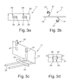
- FIGS. 3a and b is an alternative embodiment of a holder 24 to FIGS. 3a and b.
- the U-shaped recesses 29 are provided such that two are opposite each other Tabs 31 are formed, which according to Figure 3c a reinforcing rod 27 embrace.
- the holder 24 according to FIG. 3c is preferred as formed angular bracket. Due to the design of two in a plane lying legs 33 which are arranged at right angles to each other are, allows this holder 24 without use a Rödeldrahtes the joint sealing element 11 in an installed position positioned.
- the free leg 33 is advantageously in its length provided such that this at least two arranged in a grid Reinforcing bars 27 covered.
- FIG. 3c 24 an alternative embodiment of a holder is shown in FIG. 3c 24 provided.
- brackets or clips are provided, on the one hand to attack the support member 19 and on the other hand, a reinforcing rod 27 or encompass a Haiterelement. This is Klipsiata, due to their bias also without further Aids are fastened.
- These clip elements also allow the additional positioning of an injection hose to the support element 19th
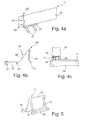
- FIG. 4 a shows a further alternative embodiment of a holder 24 shown.
- This holder 24 includes a folded edge 26, which in a vertical section 36 passes, which entanglement by 90 ° having. This is followed by a horizontal section 37, preferably extends over at least two reinforcing rods 27.
- This Holder 24 is advantageously inexpensive as a sheet metal stamped and bent part produced. Furthermore, the assembly is easy to perform.
- FIG. 4b An alternative embodiment of a holder 24 is shown in FIG. 4b.
- This holder 24 is different from that shown in Figure 4a Holder 24 formed without entanglement.
- To each side of the support member 19 positioned holder 24 is again a simple, fast and secure positioning of the jointing element 11 given.
- FIG. 4 c shows a further alternative embodiment of a holder 24 shown.
- This holder 24 is advantageously on the connection reinforcement 16 attachable or clipped.
- a centering aid or a receptacle or the like In the middle area of the stop 24 is provided a centering aid or a receptacle or the like, to position the joint sealing element 11.
- FIG. 5 shows a further alternative embodiment of a holder 24 shown.
- This holder 24 has a tab 31, which on a End has a rod 38 which extends along the support element 19th extends. At preferably regular intervals tabs 31 are arranged, to support the support member 19.
- the tabs 31 are preferred firmly attached to the support member 19, and can in the shown form are provided according to Figure 5.
- you can be provided that the voltage applied to the support member 19 prior to installation Tab 31 is bent with the rod 38 to the outside, so that the carrier 19 is independent.
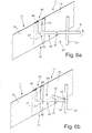
- FIGS. 6 a and b show an alternative embodiment of a holder 24 shown by way of example at an overlap region 41 of two mutually associated joint sealing elements 11 attacks. Such a Holder 24 may also outside of the overlap region 41 on the Attacking joint sealing element 11.
- the holder 24 has a strip-shaped Body 40, which includes different sections. At one End is a U-shaped holding portion 43 with a first leg 44th and a further leg 46 arranged parallel thereto, which is shown in dashed lines.
- the U-shaped holding portion 43 is located after application, preferably under bias on the side surfaces the joint sealing elements 11, to fix these adjacent to each other.
- the length of the leg 46 advantageously extends over half the width of the support member 19, in particular includes the Length of the leg 46 two thirds of the width of the support member 19th
- the leg 46 advantageously has a curb 47, which as an insertion bevel for facilitating attachment of the U-shaped holding section 43 of the holder 24 is used.
- the upstand 47 opposite Leg 44 corresponds in length to at least one fifth the width of the joint sealing element 11, so that the holding portion 43 allows an alignment function of the joint sealing element 11. At the same time, the erected position on the reinforcing bars 27 be assured.
- the leg 44 is followed by a spacer section 49, which is preferably bent at right angles to the leg 44.
- This spacer section 49 includes, for example, an entanglement 51 by 90 ° along the longitudinal axis of the strip-shaped body 40, see FIG that is a subsequent holding portion 52 having a side surface aligned parallel to a vertical reinforcing bar 27 is.
- the holding portion 52 is preferably as a rectilinear Body trained. Depending on the distance of the joint sealing element 11 to the rebar 27 or to the desired Distance, the holding portion 52 is bent around the reinforcing rod 27. Following this, by means of a pair of pliers one each Bead 54 are inserted into the holding portion 52, whereby the distance of the joint sealing element 11 to the reinforcing rod 27 set and the holding portion 52 a holding tab for further fixing the Holder 24 forms.
- This embodiment of a holder 24 has the advantage that a quick and easy attachment without the help of a metal wire is required.
- a quick and easy installation regardless of Distance of the standing joint sealing element 11 to the reinforcing bar 27 allows.
- the holders 24 are preferably arranged on the carrier element 19 such that that these alternately an upper and lower end side of the support element 19 engage around with its holding portion 43. This can be sure that while filling concrete or the Concrete vibrate the support member 19 in its vertical position to Reinforcement can be held.
- an overlap region 41 of the carrier element 19 on the underside and the other overlap region 41 of the carrier element 19 on the upper side is fixed by the holding portion 43 of the holder 24.
- the holding section 43 opposite one Retaining clip attached to the overlap area 41st to fix on both ends.
- the holder 24 according to FIGS. 6 a and b may alternatively have a spacer section 49, which at an angle between 0 ° and 90 ° is arranged to the leg 44.
- a spacer section 49 which at an angle between 0 ° and 90 ° is arranged to the leg 44.
- an angle between 30 ° and 60 ° provided and the spacer portion 49 without entanglement be formed, so that the holding portion 52 to a horizontal extending reinforcing rod is applied and for attachment to this is bent.
- a pair of pliers can in an analogous manner in each case a bead 54 are introduced into the holding section 52.
- FIG. 7 shows an alternative embodiment of a holder 24 according to FIGS Figures 6 a and b shown.
- the leg 46 extends over the entire width of the joint sealing element 11 and has a folded edge 56, which on a side edge of the joint sealing element 11th attacks.
- This holder 24 has the advantage that a simple application is made possible by first the U-shaped holding portion 43 is attached to a side edge of the joint sealing element 11 and then the folded edge 56 clipped on the other side edge becomes. When positioning the holder 24 in an overlapping area 41 can at the same time a close juxtaposition of the two End portions of the joint sealing element 11 can be achieved.
- a carrier element 19 is shown schematically and not to scale represented, for example, on one side a rough surface 61, on which an adhesive layer, a lacquer, a bituminous or swellable material is applied. Deviating from this page the opposite side of the support element 19 is formed.
- a coarse grain is provided on an adhesive layer.
- This granular material 62 may be quartz sand, silicon carbide, for example or other alternative granular material particles. These Material particles 62 are through the adhesive layer on the substrate 19 and / or by an adhesive component between the Carrier material 19 and the granular material 62 acts.
- a granulate 64 can be introduced be made of a swellable material and a protective sheath is trained.
- each granule particle is one Protective cover provided so that only when dissolving the protective sheath through the concrete due to its alkaline PH value Swelling takes place.
- the percentages of each described Components applied to this one side of the substrate 19 are, can be varied as you like.
- An advantage is a mixture, in which the material particles 62 with respect to the other in the Interspaces arranged components protrude to one To effect clawing with the adjacent concrete.
Landscapes
- Engineering & Computer Science (AREA)
- Architecture (AREA)
- Physics & Mathematics (AREA)
- Electromagnetism (AREA)
- Civil Engineering (AREA)
- Structural Engineering (AREA)
- Building Environments (AREA)
- Sealing Devices (AREA)
- Glass Compositions (AREA)
- Seal Device For Vehicle (AREA)
- Road Paving Structures (AREA)
- Sealing Material Composition (AREA)
Abstract
Description
- Figur 1
- eine schematische Schnittdarstellung eines in einer Arbeitsfuge angeordneten erfindungsgemäßen Fugendichtungselementes,
- Figur 2a/b
- eine erfindungsgemäße Ausgestaltung eines Halters für ein Fugendichtungselement,
- Figur 3a/b
- eine schematische Darstellung einer alternativen Ausgestaltung eines Halters für ein Fugendichtungselement,
- Figur 4 a-e
- weitere schematiche Darstellungen von alternativen Ausführungsformen von Haltern für Fugendichtungselemente,
- Figur 5
- eine weitere alternative Ausgestaltung eines Halters,
- Figur 6 a/b
- eine schematische Darstellung einer weiteren alternativen Ausgestaltung eines Halters ,
- Figur 7
- eine schematische Seitenansicht einer alternativen Ausgestaltung zu einem Halter zu Figur 6 a und b und
- Figur 8
- eine schematische Schnittdarstellung eines beschichteten Trägerelementes.
Claims (22)
- Fugendichtungselement zum Abdichten einer zwischen zwei Betonierabschnitten (17, 18) ausgebildeten Fuge (12), wobei das Fugendichtungselement (11) in die Betonierabschnitte (17, 18) eingebettet ist, mit einem Trägerelement (19), das dünnwandig und streifenförmig ausgebildet ist, dadurch gekennzeichnet, dass zumindest längs einer Seitenfläche des Trägerelementes (19) und in der Breite des Trägerelementes (19) zumindest abschnittsweise eine haftende Schicht vorgesehen ist, die zumindest eine Komponente aufweist, welche durch Kristallisation die Fuge (12) kapillar abdichtet.
- Fugendichtungselement nach Anspruch 1, dadurch gekennzeichnet, dass ein Anteil von wenigstens 1% der Kristallisationskomponente auf dem Trägerelement (19) vorgesehen ist.
- Fugendichtungselement nach Anspruch 1 oder 2, dadurch gekennzeichnet, dass die zumindest eine Seitenfläche des Trägerelementes (19) eine raue Oberfläche aufweist, auf der die haftende Schicht aufgebracht ist.
- Fugendichtungselement nach einem der vorhergehenden Ansprüche, dadurch gekennzeichnet, dass die Oberfläche des Trägerelementes durch Rändelung, Riffelung, Schleifen, Ätzen, Erodieren, Laserbehandeln oder Sputtern aufgeraut ist.
- Fugendichtungselement nach einem der vorhergehenden Ansprüche, dadurch gekennzeichnet, dass in der haftenden Schicht die Rauhigkeit der Oberfläche erhöhendes körniges Material eingearbeitet ist.
- Fugendichtungselement nach Anspruch 5, dadurch gekennzeichnet, dass als körniges Material Quarzsand, Siliciumcarbid, Glas-, Keramik-, Porzellan- oder metallische Teilchen eingesetzt sind.
- Fugendichtungselement nach einem der vorhergehenden Ansprüche, dadurch gekennzeichnet, dass das Trägerelement (19) eine Profilierung, insbesondere eine wellenförmige, zickzackförmige, mehrfach gekantete Querschnittsform aufweist.
- Fugendichtungselement nach einem der vorhergehenden Ansprüche, dadurch gekennzeichnet, dass der haftenden Schicht ein bituminöses Material beigemischt ist.
- Fugendichtungselement nach einem der vorhergehenden Ansprüche, dadurch gekennzeichnet, dass der haftenden Schicht zumindest ein quellfähiges Material, insbesondere Ton oder Betonit, beigefügt ist.
- Fugendichtungselement nach Anspruch 9, dadurch gekennzeichnet, dass das quellfähige Material gekörnt oder als Granulat ausgebildet ist, welches mit einem Mittel umgeben ist, welches die Körnung oder das Granulat vor dem Einbau des Trägerelementes (19) vor Wasser schützt und unter Einfluss des umgebenden Betons in eingebautem Zustand zumindest zum überwiegenden Teil sich auflöst.
- Fugendichtungselement nach Anspruch 10, dadurch gekennzeichnet, dass das Mittel ein Schutzlack, ein Klebemittel, ein Polymermaterial oder eine Kombination aus mehreren Bestandteilen ist.
- Fugendichtungselement nach einem der vorhergehenden Ansprüche, dadurch gekennzeichnet, dass der zumindest einen haftenden Schicht Kalk- oder Zementanteile beigemischt sind.
- Fugendichtungselement nach einem der vorhergehenden Ansprüche, dadurch gekennzeichnet, dass das Trägerelement (19) aus Metall, aus Kunststoff, aus einem Gewebe, aus einem Gewirke, aus einem Verbundmaterial hergestellt ist und als Fugenblech, Fugenband, Fugenfolie oder als gefüllter Schlauchbeutel ausgebildet ist.
- Fugendichtungselement nach einem der vorhergehenden Ansprüche, dadurch gekennzeichnet, dass an einer Seitenfläche des Trägerelementes (19) eine haftende Schicht und zumindest eine Kristallisationskomponente und an der anderen Seitenfläche des Trägerelementes (19) zumindest eine raue Oberfläche, eine haftende Schicht oder ein körniges Material ohne Kristallisationskomponente vorgesehen ist.
- Fugendichtungselement nach einem der vorhergehenden Ansprüche, dadurch gekennzeichnet, dass mehrere U-förmige Ausstanzungen (29) zur Bildung von Laschen (31) in dem Trägerelement (19) vorgesehen sind, die aus einer Ebene des Trägerelementes (19) heraus bewegbar sind.
- Fugendichtungselement nach Anspruch 14, dadurch gekennzeichnet, dass zwei einander gegenüberliegende U-förmige Ausstanzungen (29) in einer Ebene des Trägerelementes (19) vorgesehen sind; die einen Halteabschnitt bilden und zwei Laschen (31) gegenläufig aus der Ebene des Trägerelementes (19) heraus bewegbar sind.
- Halter, insbesondere für ein Fugendichtungselement nach einem der Ansprüche 1 bis 16, dadurch gekennzeichnet, dass ein streifenförmiger Körper vorgesehen ist, der an einem Ende zur Positionierung des Trägerelementes (19) eine Umkantung (26) aufweist und an dem gegenüberliegenden Ende einen Halteabschnitt aufweist, der einen Bewehrungsstab (27) zumindest teilweise umgreift.
- Halter, insbesondere für ein Fugendichtungselement nach einem der Ansprüche 1 bis 16, dadurch gekennzeichnet, dass ein streifenförmiger Körper vorgesehen ist, der an einem Ende zur Positionierung des Trägerelementes (19) eine Umkantung (26) aufweist und an dem gegenüberliegenden Ende einen parallel zur Längskante des Trägerelementes (19) verlaufenden Schenkel (33) umfasst, der sich zumindest über zwei parallel verlaufende Bewehrungsstäbe (27) erstreckt.
- Halter, insbesondere für ein Fugendichtungselement nach einem der Ansprüche 1 bis 16, dadurch gekennzeichnet, dass ein streifenförmiger Körper vorgesehen ist, der in einer Anschlussbewehrung (16) befestigbar ist und das Fugendichtungselement (11) in einer zwischen der Anschlussbewehrung (16) liegenden Position ausrichtet.
- Halter, insbesondere für ein Fugendichtungselement (11) nach einem der Ansprüche 1 bis 16, dadurch gekennzeichnet, dass ein streifenförmiger Körper (40) vorgesehen ist, der einen U-förmigen Halteabschnitt (43) aufweist, an den sich ein winklig dazu angeordneter Distanzabschnitt (49) anschließt, der geradlinig oder mit einer Verschränkung (51) des streifenförmigen Körpers um 90° entlang seiner Längsachse in einen Halteabschnitt (52) übergeht.
- Halter nach Anspruch 20, dadurch gekennzeichnet, dass der U-förmige Halteabschnitt (43) zwei zueinander beabstandete Schenkel (44, 46) aufweist, deren Abstand zueinander kleiner als die Dicke von einem oder von zwei sich überlappenden Fugendichtungselementen (11) ist und insbesondere einen in den Distanzabschnitt (49) übergehenden Schenkel (44) aufweist, der sich zumindest über ein Fünftel der Breite des Fugendichtungselementes (11) erstreckt.
- Halter nach einem der Ansprüche 18 oder 21, dadurch gekennzeichnet, dass der dem Distanzabschnitt (49) entfernt angeordnete Schenkel (46) des U-förmigen Halteabschnitts (43) sich vollständig entlang der Breite des Fugendichtungselementes (11) erstreckt und am freien Ende eine Umkantung (56) umfasst.
Priority Applications (1)
| Application Number | Priority Date | Filing Date | Title |
|---|---|---|---|
| EP09002248A EP2053173A1 (de) | 2004-03-28 | 2005-02-28 | Halter für Fugendichtungselemente |
Applications Claiming Priority (4)
| Application Number | Priority Date | Filing Date | Title |
|---|---|---|---|
| DE102004015507 | 2004-03-28 | ||
| DE102004015507 | 2004-03-28 | ||
| DE102005005525A DE102005005525A1 (de) | 2004-03-28 | 2005-01-31 | Fugendichtungselement und Halter für Fugendichtungselemente |
| DE102005005525 | 2005-01-31 |
Related Child Applications (2)
| Application Number | Title | Priority Date | Filing Date |
|---|---|---|---|
| EP09002248A Division EP2053173A1 (de) | 2004-03-28 | 2005-02-28 | Halter für Fugendichtungselemente |
| EP09002248.4 Division-Into | 2009-02-18 |
Publications (3)
| Publication Number | Publication Date |
|---|---|
| EP1582640A2 true EP1582640A2 (de) | 2005-10-05 |
| EP1582640A3 EP1582640A3 (de) | 2006-07-19 |
| EP1582640B1 EP1582640B1 (de) | 2010-05-26 |
Family
ID=34888820
Family Applications (2)
| Application Number | Title | Priority Date | Filing Date |
|---|---|---|---|
| EP05004300A Expired - Lifetime EP1582640B1 (de) | 2004-03-28 | 2005-02-28 | Fugendichtungselement |
| EP09002248A Withdrawn EP2053173A1 (de) | 2004-03-28 | 2005-02-28 | Halter für Fugendichtungselemente |
Family Applications After (1)
| Application Number | Title | Priority Date | Filing Date |
|---|---|---|---|
| EP09002248A Withdrawn EP2053173A1 (de) | 2004-03-28 | 2005-02-28 | Halter für Fugendichtungselemente |
Country Status (4)
| Country | Link |
|---|---|
| EP (2) | EP1582640B1 (de) |
| AT (1) | ATE469275T1 (de) |
| DE (2) | DE102005005525A1 (de) |
| DK (1) | DK1582640T3 (de) |
Cited By (1)
| Publication number | Priority date | Publication date | Assignee | Title |
|---|---|---|---|---|
| CN113863519A (zh) * | 2021-11-16 | 2021-12-31 | 中建八局第二建设有限公司 | 一种水管拦截施工缝装置及其施工方法 |
Families Citing this family (8)
| Publication number | Priority date | Publication date | Assignee | Title |
|---|---|---|---|---|
| DE102006060787A1 (de) * | 2006-12-21 | 2008-07-03 | Knauf Gips Kg | Fugenband |
| EP2060689B1 (de) * | 2007-11-14 | 2018-10-24 | Robotec-Schomburg AG | Abdichtungsvorrichtung zur Abdichtung von Arbeitsfugen |
| DE102009014309B4 (de) | 2009-03-25 | 2021-12-02 | Abdichtungs + Sanierungs-Systeme Gmbh | Dichtungselement für Betonkonstruktionen |
| DE102009044266A1 (de) * | 2009-10-16 | 2011-05-05 | Roland Wolf | Dichtelement und dessen Verwendung |
| DE202011102524U1 (de) * | 2011-06-28 | 2012-10-01 | Fwr Solutions Gmbh | Fugenabdichtvorrichtung für den Betonbau |
| DE102012021148A1 (de) | 2012-10-29 | 2014-04-30 | H-Bau Technik Gmbh | Fugenblech |
| DE202014101564U1 (de) | 2014-04-02 | 2015-07-07 | Stekox Gmbh | Befestigungselement für ein Fugenabdichtungselement |
| KR102880252B1 (ko) * | 2023-12-11 | 2025-11-04 | (주)하나 | 데크 플레이트용 지수판 상부 고정구 |
Citations (2)
| Publication number | Priority date | Publication date | Assignee | Title |
|---|---|---|---|---|
| DE29710007U1 (de) | 1997-06-03 | 1997-08-07 | Technische Produkte Handelsgesellschaft mbH, 22335 Hamburg | Stellblech zur Arbeitsfugenabdichtung im Betonbau |
| DE19935578C2 (de) | 1998-08-01 | 2001-11-29 | Fischer Gert | Fugenblech zum Abdichten von Arbeitsfugen |
Family Cites Families (8)
| Publication number | Priority date | Publication date | Assignee | Title |
|---|---|---|---|---|
| US1924724A (en) * | 1932-02-15 | 1933-08-29 | Charles M Read | Concrete wall and method of building and finishing same |
| JPS606236B2 (ja) * | 1981-02-16 | 1985-02-16 | 株式会社クラレ | 水膨潤性止水剤 |
| US5042218A (en) * | 1989-09-25 | 1991-08-27 | Gerald Nasca | Re-bar support |
| DE9206140U1 (de) * | 1992-05-07 | 1993-09-09 | Peca-Verbundtechnik Gmbh, 84130 Dingolfing | Schalung |
| US5388804A (en) * | 1993-07-19 | 1995-02-14 | Cohen; Jack H. | Anchor bolt holder-spacer |
| DE29606217U1 (de) | 1996-04-04 | 1997-08-07 | Dausend, Hans-Werner, 42289 Wuppertal | Fugenbandhalterung |
| EP0833014B1 (de) * | 1996-09-27 | 2004-06-09 | Elmenhorst Bauspezialartikel GmbH & Co.KG | Bewehrungsanordnung für ein Mauerwerk |
| DE19905691A1 (de) | 1999-02-11 | 2000-08-17 | Dausend Hans Werner | Halterung für ein Fugenband |
-
2005
- 2005-01-31 DE DE102005005525A patent/DE102005005525A1/de not_active Withdrawn
- 2005-02-28 AT AT05004300T patent/ATE469275T1/de active
- 2005-02-28 EP EP05004300A patent/EP1582640B1/de not_active Expired - Lifetime
- 2005-02-28 DE DE502005009620T patent/DE502005009620D1/de not_active Expired - Lifetime
- 2005-02-28 DK DK05004300.9T patent/DK1582640T3/da active
- 2005-02-28 EP EP09002248A patent/EP2053173A1/de not_active Withdrawn
Patent Citations (2)
| Publication number | Priority date | Publication date | Assignee | Title |
|---|---|---|---|---|
| DE29710007U1 (de) | 1997-06-03 | 1997-08-07 | Technische Produkte Handelsgesellschaft mbH, 22335 Hamburg | Stellblech zur Arbeitsfugenabdichtung im Betonbau |
| DE19935578C2 (de) | 1998-08-01 | 2001-11-29 | Fischer Gert | Fugenblech zum Abdichten von Arbeitsfugen |
Cited By (1)
| Publication number | Priority date | Publication date | Assignee | Title |
|---|---|---|---|---|
| CN113863519A (zh) * | 2021-11-16 | 2021-12-31 | 中建八局第二建设有限公司 | 一种水管拦截施工缝装置及其施工方法 |
Also Published As
| Publication number | Publication date |
|---|---|
| DE502005009620D1 (de) | 2010-07-08 |
| EP1582640A3 (de) | 2006-07-19 |
| ATE469275T1 (de) | 2010-06-15 |
| DK1582640T3 (da) | 2010-08-16 |
| DE102005005525A1 (de) | 2005-10-13 |
| EP2053173A1 (de) | 2009-04-29 |
| EP1582640B1 (de) | 2010-05-26 |
Similar Documents
| Publication | Publication Date | Title |
|---|---|---|
| DE19501384C9 (de) | Dichtungsvorrichtung zum Abdichten von Betonierfugen | |
| EP2096229B1 (de) | Abstandhalter für Dickputzsystem | |
| EP1582640A2 (de) | Fugendichtungselement und Halter für Fugendichtungselemente | |
| EP0410079B1 (de) | Anschlussschalung für aneinander anschliessende Betonplatten | |
| EP0760885A1 (de) | Sollriss-fugenschiene | |
| EP2320001B1 (de) | Vorrichtung zum Erstellen einer Teilabschalung und/oder einer Dehnungsfugen-Abschalung an einem Betonbauwerk | |
| EP1918486B1 (de) | Fliesenendabschluss-Profilschiene | |
| EP0652330A2 (de) | Betonhaltiger Formkörper für Abflussringen, Sinkkästen od. dgl. und Verfahren zu dessen Herstellung | |
| DE102019110683A1 (de) | Vorrichtung zur Abdichtung von Betonfugen | |
| DE29606107U1 (de) | Abschlußprofil bei der Wärmedämmschicht einer Gebäudewand | |
| CH702922B1 (de) | Abschlussbauelement für einen Balkon oder eine Fassade eines Gebäudes. | |
| DE2907267C2 (de) | Vorgefertigtes Deckenauflagerelement | |
| EP1956174B1 (de) | Profilschiene zum Positionieren eines Befestigungselements und Verfahren zum Herstellen einer Mehrfachverglasungseinheit | |
| DE19837080A1 (de) | Flüssigkeitsbehälter, insbesondere Klärwerksbecken, und Verfahren zur Herstellung einer Abdeckung desselben | |
| DE102004059531B4 (de) | Dämmung für eine Gebäudewand | |
| EP4063589B1 (de) | Abschalelement für den betonbau, verfahren zur herstellung eines abschalelements und verfahren zum abschalen und bewehren | |
| DE69613744T2 (de) | Schutzvorrichtung zum Verhindern des Eindringens von Wasser in eine Wand und zum Verbessern des Abführens von Wasser aus einer Wand | |
| EP1548197A1 (de) | Anordnung und Verfahren zum Abdichten von Fugen an Bauwerken, insbesondere von Dehnfugen in einer Aussenfassade | |
| DD150918A5 (de) | Dacheindeckungsplatte mit waermeleitvorrichtung | |
| AT528007B1 (de) | Anschlussprofil für an putz angrenzende bauteile mit selbstvernetzenden und/oder aushärtenden dichtmittel | |
| DE9413613U1 (de) | Fugenblech für Betonwandungen | |
| EP1970498B1 (de) | Abschlussprofilanordnung für Balkone, Terassen und dergleichen mit Plattenbelägen | |
| EP3653805B1 (de) | Anschlussprofil | |
| DE9106704U1 (de) | Halteelement für strangförmige Bauteile, insbesondere für Rohre oder Schläuche | |
| EP0716199A2 (de) | Stirnwand-Abschlussprofil für Balkone, Terrassen u.dgl. |
Legal Events
| Date | Code | Title | Description |
|---|---|---|---|
| PUAI | Public reference made under article 153(3) epc to a published international application that has entered the european phase |
Free format text: ORIGINAL CODE: 0009012 |
|
| AK | Designated contracting states |
Kind code of ref document: A2 Designated state(s): AT BE BG CH CY CZ DE DK EE ES FI FR GB GR HU IE IS IT LI LT LU MC NL PL PT RO SE SI SK TR |
|
| AX | Request for extension of the european patent |
Extension state: AL BA HR LV MK YU |
|
| PUAL | Search report despatched |
Free format text: ORIGINAL CODE: 0009013 |
|
| AK | Designated contracting states |
Kind code of ref document: A3 Designated state(s): AT BE BG CH CY CZ DE DK EE ES FI FR GB GR HU IE IS IT LI LT LU MC NL PL PT RO SE SI SK TR |
|
| AX | Request for extension of the european patent |
Extension state: AL BA HR LV MK YU |
|
| 17P | Request for examination filed |
Effective date: 20070119 |
|
| AKX | Designation fees paid |
Designated state(s): AT BE BG CH CY CZ DE DK EE ES FI FR GB GR HU IE IS IT LI LT LU MC NL PL PT RO SE SI SK TR |
|
| 17Q | First examination report despatched |
Effective date: 20080905 |
|
| GRAP | Despatch of communication of intention to grant a patent |
Free format text: ORIGINAL CODE: EPIDOSNIGR1 |
|
| RTI1 | Title (correction) |
Free format text: JOINT SEALING |
|
| GRAS | Grant fee paid |
Free format text: ORIGINAL CODE: EPIDOSNIGR3 |
|
| GRAA | (expected) grant |
Free format text: ORIGINAL CODE: 0009210 |
|
| AK | Designated contracting states |
Kind code of ref document: B1 Designated state(s): AT BE BG CH CY CZ DE DK EE ES FI FR GB GR HU IE IS IT LI LT LU MC NL PL PT RO SE SI SK TR |
|
| REG | Reference to a national code |
Ref country code: GB Ref legal event code: FG4D Free format text: NOT ENGLISH |
|
| REG | Reference to a national code |
Ref country code: CH Ref legal event code: EP |
|
| REG | Reference to a national code |
Ref country code: IE Ref legal event code: FG4D Free format text: LANGUAGE OF EP DOCUMENT: GERMAN |
|
| RAP2 | Party data changed (patent owner data changed or rights of a patent transferred) |
Owner name: STEKOX GMBH |
|
| REF | Corresponds to: |
Ref document number: 502005009620 Country of ref document: DE Date of ref document: 20100708 Kind code of ref document: P |
|
| REG | Reference to a national code |
Ref country code: DE Ref legal event code: R096 Ref document number: 502005009620 Country of ref document: DE Effective date: 20100708 |
|
| REG | Reference to a national code |
Ref country code: CH Ref legal event code: NV Representative=s name: E. BLUM & CO. AG PATENT- UND MARKENANWAELTE VSP |
|
| REG | Reference to a national code |
Ref country code: NL Ref legal event code: T3 |
|
| REG | Reference to a national code |
Ref country code: DK Ref legal event code: T3 |
|
| REG | Reference to a national code |
Ref country code: DE Ref legal event code: R081 Ref document number: 502005009620 Country of ref document: DE Owner name: AN.KOX GMBH, DE Free format text: FORMER OWNER: STEKOX GMBH, 71701 SCHWIEBERDINGEN, DE Effective date: 20100525 |
|
| LTIE | Lt: invalidation of european patent or patent extension |
Effective date: 20100526 |
|
| PG25 | Lapsed in a contracting state [announced via postgrant information from national office to epo] |
Ref country code: SE Free format text: LAPSE BECAUSE OF FAILURE TO SUBMIT A TRANSLATION OF THE DESCRIPTION OR TO PAY THE FEE WITHIN THE PRESCRIBED TIME-LIMIT Effective date: 20100526 Ref country code: LT Free format text: LAPSE BECAUSE OF FAILURE TO SUBMIT A TRANSLATION OF THE DESCRIPTION OR TO PAY THE FEE WITHIN THE PRESCRIBED TIME-LIMIT Effective date: 20100526 |
|
| PG25 | Lapsed in a contracting state [announced via postgrant information from national office to epo] |
Ref country code: SI Free format text: LAPSE BECAUSE OF FAILURE TO SUBMIT A TRANSLATION OF THE DESCRIPTION OR TO PAY THE FEE WITHIN THE PRESCRIBED TIME-LIMIT Effective date: 20100526 Ref country code: IS Free format text: LAPSE BECAUSE OF FAILURE TO SUBMIT A TRANSLATION OF THE DESCRIPTION OR TO PAY THE FEE WITHIN THE PRESCRIBED TIME-LIMIT Effective date: 20100926 Ref country code: FI Free format text: LAPSE BECAUSE OF FAILURE TO SUBMIT A TRANSLATION OF THE DESCRIPTION OR TO PAY THE FEE WITHIN THE PRESCRIBED TIME-LIMIT Effective date: 20100526 |
|
| PG25 | Lapsed in a contracting state [announced via postgrant information from national office to epo] |
Ref country code: PL Free format text: LAPSE BECAUSE OF FAILURE TO SUBMIT A TRANSLATION OF THE DESCRIPTION OR TO PAY THE FEE WITHIN THE PRESCRIBED TIME-LIMIT Effective date: 20100526 Ref country code: GR Free format text: LAPSE BECAUSE OF FAILURE TO SUBMIT A TRANSLATION OF THE DESCRIPTION OR TO PAY THE FEE WITHIN THE PRESCRIBED TIME-LIMIT Effective date: 20100827 Ref country code: CY Free format text: LAPSE BECAUSE OF FAILURE TO SUBMIT A TRANSLATION OF THE DESCRIPTION OR TO PAY THE FEE WITHIN THE PRESCRIBED TIME-LIMIT Effective date: 20100526 |
|
| REG | Reference to a national code |
Ref country code: IE Ref legal event code: FD4D |
|
| PG25 | Lapsed in a contracting state [announced via postgrant information from national office to epo] |
Ref country code: PT Free format text: LAPSE BECAUSE OF FAILURE TO SUBMIT A TRANSLATION OF THE DESCRIPTION OR TO PAY THE FEE WITHIN THE PRESCRIBED TIME-LIMIT Effective date: 20100927 Ref country code: IE Free format text: LAPSE BECAUSE OF FAILURE TO SUBMIT A TRANSLATION OF THE DESCRIPTION OR TO PAY THE FEE WITHIN THE PRESCRIBED TIME-LIMIT Effective date: 20100526 Ref country code: EE Free format text: LAPSE BECAUSE OF FAILURE TO SUBMIT A TRANSLATION OF THE DESCRIPTION OR TO PAY THE FEE WITHIN THE PRESCRIBED TIME-LIMIT Effective date: 20100526 |
|
| PG25 | Lapsed in a contracting state [announced via postgrant information from national office to epo] |
Ref country code: SK Free format text: LAPSE BECAUSE OF FAILURE TO SUBMIT A TRANSLATION OF THE DESCRIPTION OR TO PAY THE FEE WITHIN THE PRESCRIBED TIME-LIMIT Effective date: 20100526 Ref country code: RO Free format text: LAPSE BECAUSE OF FAILURE TO SUBMIT A TRANSLATION OF THE DESCRIPTION OR TO PAY THE FEE WITHIN THE PRESCRIBED TIME-LIMIT Effective date: 20100526 Ref country code: CZ Free format text: LAPSE BECAUSE OF FAILURE TO SUBMIT A TRANSLATION OF THE DESCRIPTION OR TO PAY THE FEE WITHIN THE PRESCRIBED TIME-LIMIT Effective date: 20100526 |
|
| PLBE | No opposition filed within time limit |
Free format text: ORIGINAL CODE: 0009261 |
|
| STAA | Information on the status of an ep patent application or granted ep patent |
Free format text: STATUS: NO OPPOSITION FILED WITHIN TIME LIMIT |
|
| 26N | No opposition filed |
Effective date: 20110301 |
|
| REG | Reference to a national code |
Ref country code: DE Ref legal event code: R097 Ref document number: 502005009620 Country of ref document: DE Effective date: 20110228 Ref country code: DE Ref legal event code: R097 Ref document number: 502005009620 Country of ref document: DE Effective date: 20110301 |
|
| PG25 | Lapsed in a contracting state [announced via postgrant information from national office to epo] |
Ref country code: MC Free format text: LAPSE BECAUSE OF NON-PAYMENT OF DUE FEES Effective date: 20110228 |
|
| PG25 | Lapsed in a contracting state [announced via postgrant information from national office to epo] |
Ref country code: LU Free format text: LAPSE BECAUSE OF NON-PAYMENT OF DUE FEES Effective date: 20110228 |
|
| PG25 | Lapsed in a contracting state [announced via postgrant information from national office to epo] |
Ref country code: BG Free format text: LAPSE BECAUSE OF FAILURE TO SUBMIT A TRANSLATION OF THE DESCRIPTION OR TO PAY THE FEE WITHIN THE PRESCRIBED TIME-LIMIT Effective date: 20100826 Ref country code: TR Free format text: LAPSE BECAUSE OF FAILURE TO SUBMIT A TRANSLATION OF THE DESCRIPTION OR TO PAY THE FEE WITHIN THE PRESCRIBED TIME-LIMIT Effective date: 20100526 |
|
| PG25 | Lapsed in a contracting state [announced via postgrant information from national office to epo] |
Ref country code: HU Free format text: LAPSE BECAUSE OF FAILURE TO SUBMIT A TRANSLATION OF THE DESCRIPTION OR TO PAY THE FEE WITHIN THE PRESCRIBED TIME-LIMIT Effective date: 20100526 Ref country code: ES Free format text: LAPSE BECAUSE OF FAILURE TO SUBMIT A TRANSLATION OF THE DESCRIPTION OR TO PAY THE FEE WITHIN THE PRESCRIBED TIME-LIMIT Effective date: 20100906 |
|
| REG | Reference to a national code |
Ref country code: FR Ref legal event code: PLFP Year of fee payment: 12 |
|
| REG | Reference to a national code |
Ref country code: FR Ref legal event code: PLFP Year of fee payment: 13 |
|
| REG | Reference to a national code |
Ref country code: FR Ref legal event code: PLFP Year of fee payment: 14 |
|
| REG | Reference to a national code |
Ref country code: DE Ref legal event code: R082 Ref document number: 502005009620 Country of ref document: DE Representative=s name: MAMMEL UND MASER, PATENTANWAELTE, DE Ref country code: DE Ref legal event code: R081 Ref document number: 502005009620 Country of ref document: DE Owner name: AN.KOX GMBH, DE Free format text: FORMER OWNER: STEKOX GMBH, 71106 MAGSTADT, DE Ref country code: DE Ref legal event code: R081 Ref document number: 502005009620 Country of ref document: DE Owner name: ANKOX GMBH, DE Free format text: FORMER OWNER: STEKOX GMBH, 71106 MAGSTADT, DE |
|
| REG | Reference to a national code |
Ref country code: DE Ref legal event code: R082 Ref document number: 502005009620 Country of ref document: DE Representative=s name: MAMMEL UND MASER, PATENTANWAELTE, DE Ref country code: DE Ref legal event code: R081 Ref document number: 502005009620 Country of ref document: DE Owner name: AN.KOX GMBH, DE Free format text: FORMER OWNER: ANKOX GMBH, 71106 MAGSTADT, DE Ref country code: DE Ref legal event code: R081 Ref document number: 502005009620 Country of ref document: DE Owner name: ANKOX GMBH, DE Free format text: FORMER OWNER: ANKOX GMBH, 71106 MAGSTADT, DE Ref country code: CH Ref legal event code: PFA Owner name: ANKOX GMBH, DE Free format text: FORMER OWNER: ANKOX GMBH, DE Ref country code: CH Ref legal event code: PFA Owner name: ANKOX GMBH, DE Free format text: FORMER OWNER: STEKOX GMBH, DE |
|
| REG | Reference to a national code |
Ref country code: BE Ref legal event code: HC Owner name: ANKOX GMBH; DE Free format text: DETAILS ASSIGNMENT: CHANGE OF OWNER(S), CHANGEMENT DE NOM DU PROPRIETAIRE Effective date: 20190108 |
|
| REG | Reference to a national code |
Ref country code: NL Ref legal event code: HC Owner name: ANKOX GMBH; DE Free format text: DETAILS ASSIGNMENT: CHANGE OF OWNER(S), CHANGE OF OWNER(S) NAME; FORMER OWNER NAME: STEKOX GMBH Effective date: 20181221 |
|
| REG | Reference to a national code |
Ref country code: AT Ref legal event code: HC Ref document number: 469275 Country of ref document: AT Kind code of ref document: T Owner name: ANKOX GMBH, DE Effective date: 20190306 |
|
| PGFP | Annual fee paid to national office [announced via postgrant information from national office to epo] |
Ref country code: GB Payment date: 20200219 Year of fee payment: 16 Ref country code: DK Payment date: 20200211 Year of fee payment: 16 Ref country code: IT Payment date: 20200128 Year of fee payment: 16 Ref country code: AT Payment date: 20200127 Year of fee payment: 16 |
|
| PGFP | Annual fee paid to national office [announced via postgrant information from national office to epo] |
Ref country code: FR Payment date: 20200127 Year of fee payment: 16 |
|
| REG | Reference to a national code |
Ref country code: DE Ref legal event code: R082 Ref document number: 502005009620 Country of ref document: DE Representative=s name: MAMMEL UND MASER, PATENTANWAELTE, DE Ref country code: DE Ref legal event code: R081 Ref document number: 502005009620 Country of ref document: DE Owner name: AN.KOX GMBH, DE Free format text: FORMER OWNER: ANKOX GMBH, 71106 MAGSTADT, DE |
|
| REG | Reference to a national code |
Ref country code: DK Ref legal event code: EBP Effective date: 20210228 |
|
| REG | Reference to a national code |
Ref country code: AT Ref legal event code: MM01 Ref document number: 469275 Country of ref document: AT Kind code of ref document: T Effective date: 20210228 |
|
| GBPC | Gb: european patent ceased through non-payment of renewal fee |
Effective date: 20210228 |
|
| PG25 | Lapsed in a contracting state [announced via postgrant information from national office to epo] |
Ref country code: AT Free format text: LAPSE BECAUSE OF NON-PAYMENT OF DUE FEES Effective date: 20210228 |
|
| PG25 | Lapsed in a contracting state [announced via postgrant information from national office to epo] |
Ref country code: GB Free format text: LAPSE BECAUSE OF NON-PAYMENT OF DUE FEES Effective date: 20210228 Ref country code: FR Free format text: LAPSE BECAUSE OF NON-PAYMENT OF DUE FEES Effective date: 20210228 Ref country code: DK Free format text: LAPSE BECAUSE OF NON-PAYMENT OF DUE FEES Effective date: 20210228 |
|
| PG25 | Lapsed in a contracting state [announced via postgrant information from national office to epo] |
Ref country code: IT Free format text: LAPSE BECAUSE OF NON-PAYMENT OF DUE FEES Effective date: 20210228 |
|
| P01 | Opt-out of the competence of the unified patent court (upc) registered |
Effective date: 20230516 |
|
| PGFP | Annual fee paid to national office [announced via postgrant information from national office to epo] |
Ref country code: NL Payment date: 20240108 Year of fee payment: 20 |
|
| PGFP | Annual fee paid to national office [announced via postgrant information from national office to epo] |
Ref country code: DE Payment date: 20240222 Year of fee payment: 20 Ref country code: CH Payment date: 20240301 Year of fee payment: 20 |
|
| PGFP | Annual fee paid to national office [announced via postgrant information from national office to epo] |
Ref country code: BE Payment date: 20240105 Year of fee payment: 20 |
|
| REG | Reference to a national code |
Ref country code: DE Ref legal event code: R071 Ref document number: 502005009620 Country of ref document: DE Ref country code: CH Ref legal event code: PL |
|
| REG | Reference to a national code |
Ref country code: NL Ref legal event code: MK Effective date: 20250227 |
|
| REG | Reference to a national code |
Ref country code: BE Ref legal event code: MK Effective date: 20250228 |