EP1583175A2 - Unité d'antenne à large bande - Google Patents
Unité d'antenne à large bande Download PDFInfo
- Publication number
- EP1583175A2 EP1583175A2 EP05250496A EP05250496A EP1583175A2 EP 1583175 A2 EP1583175 A2 EP 1583175A2 EP 05250496 A EP05250496 A EP 05250496A EP 05250496 A EP05250496 A EP 05250496A EP 1583175 A2 EP1583175 A2 EP 1583175A2
- Authority
- EP
- European Patent Office
- Prior art keywords
- antenna
- expanding
- antenna unit
- inverted triangular
- conductor pattern
- Prior art date
- Legal status (The legal status is an assumption and is not a legal conclusion. Google has not performed a legal analysis and makes no representation as to the accuracy of the status listed.)
- Withdrawn
Links
Images

Classifications
-
- H—ELECTRICITY
- H01—ELECTRIC ELEMENTS
- H01Q—ANTENNAS, i.e. RADIO AERIALS
- H01Q9/00—Electrically-short antennas having dimensions not more than twice the operating wavelength and consisting of conductive active radiating elements
- H01Q9/04—Resonant antennas
- H01Q9/30—Resonant antennas with feed to end of elongated active element, e.g. unipole
- H01Q9/40—Element having extended radiating surface
-
- H—ELECTRICITY
- H01—ELECTRIC ELEMENTS
- H01Q—ANTENNAS, i.e. RADIO AERIALS
- H01Q1/00—Details of, or arrangements associated with, antennas
- H01Q1/40—Radiating elements coated with or embedded in protective material
-
- H—ELECTRICITY
- H01—ELECTRIC ELEMENTS
- H01Q—ANTENNAS, i.e. RADIO AERIALS
- H01Q19/00—Combinations of primary active antenna elements and units with secondary devices, e.g. with quasi-optical devices, for giving the antenna a desired directional characteristic
- H01Q19/06—Combinations of primary active antenna elements and units with secondary devices, e.g. with quasi-optical devices, for giving the antenna a desired directional characteristic using refracting or diffracting devices, e.g. lens
- H01Q19/09—Combinations of primary active antenna elements and units with secondary devices, e.g. with quasi-optical devices, for giving the antenna a desired directional characteristic using refracting or diffracting devices, e.g. lens wherein the primary active element is coated with or embedded in a dielectric or magnetic material
Definitions
- This invention relates to an antenna unit and, in particular, to an antenna unit for an ultra wideband (UWB).
- UWB ultra wideband
- the UWB technology means an ultra wideband radio technology and is a broad term representative of a radio transmission system that occupies a bandwidth of at least 25% of a center frequency or a bandwidth wider than 1.5 GHz.
- the UWB technology is a revolutionary radio technology for carrying out communication using short pulses (typically having a pulse width of 1 ns or less) of an ultra wideband.
- a key difference between the UWB technology and the traditional radio technology is presence or absence of a carrier wave.
- a sinusoidal wave having a certain frequency called a carrier wave
- the UWB technology does not use the carrier wave but uses the short pulses of an ultra wideband as described above.
- the traditional radio technology uses a narrow frequency band. This is because communication using a narrow frequency band allows an effective use of a radio wave which is a finite resource.
- the UWB technology uses an ultra wide frequency band. Nevertheless, the UWB technology occupying an ultra wideband attracts increasing attention. The reason resides in output energy at each frequency.
- the frequency band is very wide but output power at each frequency is very low. Since the output power has a very low level below a noise level, an interference between UWB communication and other radio communications is extremely small.
- the UWB communication extends over an ultra wideband which overlaps frequency bands of existing radio communication services. Therefore, the band for the UWB communication is limited to a range from 3.1 GHz to 10.6 GHz at present.
- an antenna basically utilizes a resonance phenomenon.
- the antenna has a resonance frequency determined by its length.
- UWB communication including a number of frequency components, it is difficult to cause a resonance.
- a patch antenna is known as a compact antenna.
- a compact flat patch antenna is disclosed, for example, in Japanese Unexamined Patent Application Publication (JP-A) No. H7-94934.
- the flat patch antenna is excellent in portability, high in frequency temperature characteristic, suppressed in variation of the resonance frequency, and excellent in reliability.
- a patch antenna unit adaptable to a plurality of frequencies is disclosed, for example, in Japanese Unexamined Patent Application Publication (JP-A) No. H10-190347.
- the patch antenna does not cover a wideband and is therefore unsuitable for use as a UWB antenna.
- TAIYO YUDEN CO., LTD., Tokyo, Japan has successfully developed a very small ceramic chip antenna for UWB which is recognized as a next-generation technology that will simultaneously achieve high-rate data transmission and low power consumption in the field of short-range radio communication.
- the ceramic chip antenna has a size of 10 mm x 8 mm and a thickness as small as 1 mm.
- the UWB technology traditionally limited to military applications is now released for commercial use, for example, high-speed connection of data between digital equipments such as a PDP (Plasma Display Panel) television and a digital camera. It is therefore possible to miniaturize various equipments, including mobile equipments.
- Such a UWB antenna may be used for various applications such as Bluetooth (registered trademark) and wireless LAN (Local Area Network).
- Bluetooth is an open standard for an advanced technology for realizing wireless data and voice communication in a relatively short range between desktop and notebook computers, PDAs (Personal Digital Assistants), mobile telephones, printers, scanners, digital cameras, and home electric appliances, and so on. Bluetooth is operable using a radio wave in a worldwide available 2.4 GHz band and, therefore, can be used throughout the world. Briefly speaking, use of Bluetooth makes it possible to connect digital peripheral devices without cables. Therefore, any trouble associated with cable connection is a matter of the past.
- the wireless LAN is a LAN using a transmission path, such as a radio wave or an infrared ray, except a cable and a wire.
- an existing antenna such as a patch antenna is disadvantageous in that it is difficult to cover a wideband and waveform distortion (waveform broadening or widening) occurs. Further, an antenna characteristic is excellent if a voltage standing wave ratio (VSWR) is as low as possible.
- VSWR voltage standing wave ratio
- the existing antenna can not lower the VSWR in a highfrequency range. In other words, the VSWR inevitably becomes high in a highfrequency range.
- an antenna unit comprising an upper dielectric member, a lower dielectric member, and a conductor pattern interposed between the upper and the lower dielectric members, the conductor pattern having a feeding point at a generally center portion of a front surface of the antenna unit and comprising an inverted triangular portion having a right tapered portion and a left tapered portion extending from the feeding point towards a right side surface and a left side surface of the antenna unit with a predetermined angle, respectively, a main expanding portion expanding from an upper side of the inverted triangular portion, a right expanding portion expanding from the right tapered portion, and a left expanding portion expanding from the left tapered portion.
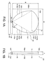
- a UWB antenna as an antenna unit according to an embodiment of this invention.
- the UWB antenna depicted by a reference numeral 10 has, as a whole external appearance, a shape of a rectangular solid (rectangular plate) with a length B (in a vertical direction in Fig. 1A), a width W (in a horizontal direction in Fig. 1A), and a thickness T.
- the length B is equal to 10.1 mm
- the width W is equal to 10.1 mm
- the thickness T is equal to 0.8 mm.
- the UWB antenna 10 has an upper surface 10u, a bottom surface 10d, a front surface 10f, a back surface 10b, a right side surface 10rs, and a left side surface 10ls.
- the UWB antenna 10 comprises an upper rectangular dielectric member 11, a lower rectangular dielectric member 13, and a conductor pattern 15 interposed between the upper and the lower rectangular dielectric members 11 and 13.
- Each of the upper and the lower rectangular dielectric members 11 and 13 has a length B, a width W, and a thickness T/2.
- the conductor pattern 15 is made of a material such as a silver paste and has a thickness of about 8 ⁇ m.
- Each of the upper and the lower rectangular dielectric members 11 and 13 has a specific dielectric constant ⁇ r.
- the specific dielectric constant ⁇ r is equal to 4.4.
- each of the upper and the lower rectangular dielectric members 11 and 13 comprises a ceramic plate.
- the conductor pattern 15 has a feeding point 151 at a generally center portion of the front surface 10f.
- the feeding point 151 of the conductor pattern 15 is electrically connected to a ground member 20 having a length G and a width W.
- the length G is equal to 0.8 mm.
- the conductor pattern 15 has an inverted triangular portion 15-1 having a right tapered portion 152 and a left tapered portion 153 extending from the feeding point 151 towards the right side surface 10rs and the left side surface 10ls with a predetermined angle ⁇ , respectively, a main expanding portion 15-2 expanding from an upper side 154 of the inverted triangular portion 15-1, a right expanding portion 15-3 expanding from the right tapered portion 152, and a left expanding portion 15-4 expanding from the left tapered portion 153.
- the main expanding portion 15-2, the right expanding portion 15-3, and the left expanding portion 15-4 are integral with the inverted triangular portion 15-1.
- the predetermined angle ⁇ is equal to 60°. Accordingly, the inverted triangular portion 15-1 is an equilateral triangle.
- the main expanding portion 15-2 is defined by an arc 15-2a connecting opposite ends of the upper side 154 of the inverted triangular portion 15-1.
- the upper side 154 of the inverted triangular portion 15-1 is in closely contact with a base side of the main expanding portion 15-2.
- the upper side 154 serves as the base side of the main expanding portion 15-2.
- the arc 15-2a has a center coincident with centers of the length B and the width W.
- the right and the left expanding portions 15-3 and 15-4 are defined by a smooth right curve 15-3a and a smooth left curve 15-4a, respectively.
- the right and the left curves 15-3a and 15-4a connect an apex of the inverted triangular portion 15-1 and the opposite ends of the upper side 154, respectively, and are symmetrical with each other.
- the conductor pattern 15 is interposed between the upper and the lower rectangular dielectric members 11 and 13. Further, the conductor pattern 15 has the feeding point 151 and the right and the left tapered portions 152 and 153 extending rightward and leftward from the feeding point 151 with the predetermined angle. Thus, the UWB antenna of a wideband can be obtained.
- the conductor pattern 15 has the right and the left expanding portions 15-3 and 15-4 expanding from the right and the left tapered portions 152 and 153, respectively. Therefore, even in a highfrequency range, a low VSWR is maintained. It is consequently possible to further improve frequency characteristics.
- z 0 and y 0 are equal to 7.60 mm and 4.39 mm, respectively.
- y y 0 - ⁇ e a(z0-z) - 1 ⁇
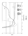
- an abscissa represents the frequency (GHz) while an ordinate represents the VSWR.
- an ordinate represents the VSWR.
- three types of conductor patterns are shown.
- a lower VSWR represents a superior antenna characteristic.
- a first characteristic curve T1 represents the antenna characteristic of an antenna having the conductor pattern 15 illustrated in Fig. 1, i.e., the first conductor pattern Type 1.
- a second characteristic curve T2 represents the antenna characteristic of the second conductor pattern Type 2.
- a third characteristic curve T3 represents the antenna characteristic of the third conductor pattern Type 3.
- the first characteristic curve T1 has a low VSWR at a relatively high frequency, i.e., a frequency higher than about 5 GHz. Therefore, the antenna having the first conductor pattern Type 1 exhibits an excellent antenna characteristic. Thus, the UWB antenna illustrated in Fig. 1 is excellent in antenna characteristic.
- the second characteristic curve T2 has a low VSWR only in a frequency range from about 3.5 to about 4.8 GHz but has a high VSWR at other frequencies.
- an antenna having the second conductor pattern Type 2 is inferior in antenna characteristic.
- the third characteristic curve T3 has a low VSWR only in a frequency range from about 3 to about 4 GHz but has an extremely high VSWR at other frequencies.
- an antenna having the third conductor pattern Type 3 is also inferior in antenna characteristic.
Landscapes
- Details Of Aerials (AREA)
- Waveguide Aerials (AREA)
Applications Claiming Priority (2)
| Application Number | Priority Date | Filing Date | Title |
|---|---|---|---|
| JP2004110212A JP2005295390A (ja) | 2004-04-02 | 2004-04-02 | アンテナ装置 |
| JP2004110212 | 2004-04-02 |
Publications (2)
| Publication Number | Publication Date |
|---|---|
| EP1583175A2 true EP1583175A2 (fr) | 2005-10-05 |
| EP1583175A3 EP1583175A3 (fr) | 2006-06-21 |
Family
ID=34880135
Family Applications (1)
| Application Number | Title | Priority Date | Filing Date |
|---|---|---|---|
| EP05250496A Withdrawn EP1583175A3 (fr) | 2004-04-02 | 2005-01-31 | Unité d'antenne à large bande |
Country Status (4)
| Country | Link |
|---|---|
| US (1) | US7091909B2 (fr) |
| EP (1) | EP1583175A3 (fr) |
| JP (1) | JP2005295390A (fr) |
| CN (1) | CN1677745A (fr) |
Cited By (1)
| Publication number | Priority date | Publication date | Assignee | Title |
|---|---|---|---|---|
| FR2911725A1 (fr) * | 2007-01-24 | 2008-07-25 | Groupe Ecoles Telecomm | Antenne ou element d'antenne ultra-large bande. |
Families Citing this family (8)
| Publication number | Priority date | Publication date | Assignee | Title |
|---|---|---|---|---|
| CN2512043Y (zh) * | 2001-12-29 | 2002-09-18 | 台均实业有限公司 | 具有柔性隔膜式电磁感应发生装置的电子白板 |
| US7872607B2 (en) * | 2006-01-27 | 2011-01-18 | Qualcomm, Incorporated | Diverse spectrum antenna for handsets and other devices |
| JP2007235395A (ja) * | 2006-02-28 | 2007-09-13 | Mitsumi Electric Co Ltd | 広帯域アンテナ装置 |
| JP4844748B2 (ja) * | 2007-03-15 | 2011-12-28 | ミツミ電機株式会社 | 広帯域アンテナ装置 |
| US8232922B2 (en) * | 2008-01-25 | 2012-07-31 | Dublin Institute Of Technology | Ultra wide band antenna with a spline curve radiating element |
| KR101082775B1 (ko) * | 2008-06-23 | 2011-11-14 | (주)파트론 | 광대역 패치 안테나 및 그것을 이용한 중계기 |
| MX357478B (es) * | 2013-08-20 | 2018-07-11 | Voxx Int Corp | Antena de alambre plana, ultra-delgada y flexible, de perfil bajo, de banda ancha. |
| EP3270461B1 (fr) * | 2016-07-14 | 2020-11-04 | Advanced Automotive Antennas, S.L. | Système d'antenne à large bande pour véhicule |
Family Cites Families (9)
| Publication number | Priority date | Publication date | Assignee | Title |
|---|---|---|---|---|
| US3815141A (en) * | 1973-01-12 | 1974-06-04 | E Kigler | High frequency antenna |
| JPS57142003A (en) * | 1981-02-27 | 1982-09-02 | Denki Kogyo Kk | Antenna |
| DE3300677C2 (de) * | 1983-01-11 | 1986-12-18 | O.D.A.M. - Office de Distribution d'Appareils Médicaux, Wissembourg | Applikator zum Zuführen und/oder Abführen von Hochfrequenzenergie |
| FR2683952A1 (fr) * | 1991-11-14 | 1993-05-21 | Dassault Electronique | Dispositif d'antenne microruban perfectionne, notamment pour transmissions telephoniques par satellite. |
| JPH0794934A (ja) | 1993-09-22 | 1995-04-07 | Matsushita Electric Ind Co Ltd | 小型平面パッチアンテナ |
| JPH10513329A (ja) * | 1995-02-06 | 1998-12-15 | メガウエイブ コーポレーション | 窓ガラスアンテナ |
| JPH10190347A (ja) | 1996-12-26 | 1998-07-21 | Nippon Avionics Co Ltd | パッチアンテナ装置 |
| EP1270168B1 (fr) * | 2001-06-25 | 2006-02-22 | The Furukawa Electric Co., Ltd. | Antenne monopuce et son procédé de fabrication |
| US6768461B2 (en) * | 2001-08-16 | 2004-07-27 | Arc Wireless Solutions, Inc. | Ultra-broadband thin planar antenna |
-
2004
- 2004-04-02 JP JP2004110212A patent/JP2005295390A/ja active Pending
-
2005
- 2005-01-10 CN CN200510000390.3A patent/CN1677745A/zh active Pending
- 2005-01-28 US US11/046,391 patent/US7091909B2/en not_active Expired - Lifetime
- 2005-01-31 EP EP05250496A patent/EP1583175A3/fr not_active Withdrawn
Cited By (4)
| Publication number | Priority date | Publication date | Assignee | Title |
|---|---|---|---|---|
| FR2911725A1 (fr) * | 2007-01-24 | 2008-07-25 | Groupe Ecoles Telecomm | Antenne ou element d'antenne ultra-large bande. |
| WO2008090204A1 (fr) * | 2007-01-24 | 2008-07-31 | Groupe Des Ecoles Des Telecommunications (Enst Bretagne) | Antenne ou element d'antenne ultra-large bande |
| CN101627506B (zh) * | 2007-01-24 | 2013-05-08 | 电讯集团学校国际电讯学院(恩斯特布列塔尼) | 超宽带天线或天线构件 |
| US8791872B2 (en) | 2007-01-24 | 2014-07-29 | Groupe des Ecoles des Telecommunications (ENST Bretange) | Ultra wide band antenna or antenna member |
Also Published As
| Publication number | Publication date |
|---|---|
| CN1677745A (zh) | 2005-10-05 |
| US20050219127A1 (en) | 2005-10-06 |
| US7091909B2 (en) | 2006-08-15 |
| EP1583175A3 (fr) | 2006-06-21 |
| JP2005295390A (ja) | 2005-10-20 |
Similar Documents
| Publication | Publication Date | Title |
|---|---|---|
| US7081859B2 (en) | Antenna unit having a wide band | |
| US5945954A (en) | Antenna assembly for telecommunication devices | |
| JP4499676B2 (ja) | 広帯域アンテナ装置 | |
| US7405697B2 (en) | Compact diversity antenna | |
| CN1164009C (zh) | 具有两个有源辐射器的天线 | |
| EP4152519A1 (fr) | Dispositif électronique | |
| TWI321376B (en) | Directional antenna | |
| EP1962378A1 (fr) | Unité d'antenne de bande large comprenant une partie d'antenne monopôle en forme de plaque pliée et une partie extensible | |
| US8310406B2 (en) | Antenna device | |
| EP2043195A1 (fr) | Antenne à bande large comprenant une antenne monopôle en forme de plaque pliée et deux éléments conducteurs | |
| EP1460713A1 (fr) | Antenne-diversité compacte | |
| JP3964382B2 (ja) | アンテナ装置 | |
| US7091909B2 (en) | Antenna unit adaptable to a wideband | |
| US11189916B2 (en) | Double-frequency antenna structure with high isolation | |
| EP1717902A1 (fr) | Antennes monopoles planaires | |
| US8232927B2 (en) | Antenna element | |
| KR101903990B1 (ko) | 이중대역 슬롯 안테나 | |
| WO2023240987A1 (fr) | Ensemble antenne et dispositif électronique | |
| JP2002299945A (ja) | マイクロストリップアンテナ | |
| JP4067041B2 (ja) | プレートアンテナおよびそのアンテナを備える通信端末 | |
| KR100640339B1 (ko) | 광대역 모노폴 안테나 | |
| JP4935256B2 (ja) | アンテナ装置 | |
| US11600925B2 (en) | Antenna structure | |
| US12621379B2 (en) | Electronic device | |
| KR100438423B1 (ko) | 평면 안테나 및 그 급전구조 |
Legal Events
| Date | Code | Title | Description |
|---|---|---|---|
| PUAI | Public reference made under article 153(3) epc to a published international application that has entered the european phase |
Free format text: ORIGINAL CODE: 0009012 |
|
| AK | Designated contracting states |
Kind code of ref document: A2 Designated state(s): AT BE BG CH CY CZ DE DK EE ES FI FR GB GR HU IE IS IT LI LT LU MC NL PL PT RO SE SI SK TR |
|
| AX | Request for extension of the european patent |
Extension state: AL BA HR LV MK YU |
|
| PUAL | Search report despatched |
Free format text: ORIGINAL CODE: 0009013 |
|
| AK | Designated contracting states |
Kind code of ref document: A3 Designated state(s): AT BE BG CH CY CZ DE DK EE ES FI FR GB GR HU IE IS IT LI LT LU MC NL PL PT RO SE SI SK TR |
|
| AX | Request for extension of the european patent |
Extension state: AL BA HR LV MK YU |
|
| 17P | Request for examination filed |
Effective date: 20061212 |
|
| AKX | Designation fees paid |
Designated state(s): DE GB |
|
| 17Q | First examination report despatched |
Effective date: 20070914 |
|
| STAA | Information on the status of an ep patent application or granted ep patent |
Free format text: STATUS: THE APPLICATION IS DEEMED TO BE WITHDRAWN |
|
| 18D | Application deemed to be withdrawn |
Effective date: 20090801 |