EP1583401A1 - Zeremonielle Vorrichtung - Google Patents
Zeremonielle Vorrichtung Download PDFInfo
- Publication number
- EP1583401A1 EP1583401A1 EP04007919A EP04007919A EP1583401A1 EP 1583401 A1 EP1583401 A1 EP 1583401A1 EP 04007919 A EP04007919 A EP 04007919A EP 04007919 A EP04007919 A EP 04007919A EP 1583401 A1 EP1583401 A1 EP 1583401A1
- Authority
- EP
- European Patent Office
- Prior art keywords
- installation according
- interface
- programmer
- source
- installation
- Prior art date
- Legal status (The legal status is an assumption and is not a legal conclusion. Google has not performed a legal analysis and makes no representation as to the accuracy of the status listed.)
- Withdrawn
Links
- 230000005855 radiation Effects 0.000 claims abstract description 20
- 238000009434 installation Methods 0.000 claims description 63
- 230000006698 induction Effects 0.000 claims description 15
- 230000035622 drinking Effects 0.000 claims description 14
- 230000006870 function Effects 0.000 claims description 11
- 230000008878 coupling Effects 0.000 claims description 9
- 238000010168 coupling process Methods 0.000 claims description 9
- 238000005859 coupling reaction Methods 0.000 claims description 9
- 238000012876 topography Methods 0.000 claims description 8
- 230000005670 electromagnetic radiation Effects 0.000 claims description 7
- 238000000926 separation method Methods 0.000 claims description 4
- 230000004913 activation Effects 0.000 claims description 2
- 239000011521 glass Substances 0.000 abstract description 52
- 230000004044 response Effects 0.000 description 7
- 230000008859 change Effects 0.000 description 6
- 239000000463 material Substances 0.000 description 6
- 210000000056 organ Anatomy 0.000 description 6
- 230000006399 behavior Effects 0.000 description 5
- 230000000694 effects Effects 0.000 description 4
- 238000002604 ultrasonography Methods 0.000 description 4
- 238000004891 communication Methods 0.000 description 3
- 230000001276 controlling effect Effects 0.000 description 3
- 238000000034 method Methods 0.000 description 3
- 241001465754 Metazoa Species 0.000 description 2
- 241001639412 Verres Species 0.000 description 2
- 230000009471 action Effects 0.000 description 2
- 230000005540 biological transmission Effects 0.000 description 2
- 238000005034 decoration Methods 0.000 description 2
- 238000010586 diagram Methods 0.000 description 2
- 239000007788 liquid Substances 0.000 description 2
- 230000011664 signaling Effects 0.000 description 2
- 239000000853 adhesive Substances 0.000 description 1
- 238000013459 approach Methods 0.000 description 1
- 230000004888 barrier function Effects 0.000 description 1
- 230000008901 benefit Effects 0.000 description 1
- 235000013361 beverage Nutrition 0.000 description 1
- 239000003990 capacitor Substances 0.000 description 1
- 230000004456 color vision Effects 0.000 description 1
- 239000000470 constituent Substances 0.000 description 1
- 230000005611 electricity Effects 0.000 description 1
- 230000004438 eyesight Effects 0.000 description 1
- 239000011888 foil Substances 0.000 description 1
- 239000000446 fuel Substances 0.000 description 1
- 230000001939 inductive effect Effects 0.000 description 1
- 238000002329 infrared spectrum Methods 0.000 description 1
- 239000003550 marker Substances 0.000 description 1
- 239000002184 metal Substances 0.000 description 1
- 230000000737 periodic effect Effects 0.000 description 1
- 238000002360 preparation method Methods 0.000 description 1
- 230000008569 process Effects 0.000 description 1
- 230000001105 regulatory effect Effects 0.000 description 1
- 238000002211 ultraviolet spectrum Methods 0.000 description 1
- 238000005406 washing Methods 0.000 description 1
- XLYOFNOQVPJJNP-UHFFFAOYSA-N water Substances O XLYOFNOQVPJJNP-UHFFFAOYSA-N 0.000 description 1
Images
Classifications
-
- A—HUMAN NECESSITIES
- A47—FURNITURE; DOMESTIC ARTICLES OR APPLIANCES; COFFEE MILLS; SPICE MILLS; SUCTION CLEANERS IN GENERAL
- A47G—HOUSEHOLD OR TABLE EQUIPMENT
- A47G19/00—Table service
- A47G19/22—Drinking vessels or saucers used for table service
- A47G19/2205—Drinking glasses or vessels
- A47G19/2227—Drinking glasses or vessels with means for amusing or giving information to the user
-
- H—ELECTRICITY
- H05—ELECTRIC TECHNIQUES NOT OTHERWISE PROVIDED FOR
- H05B—ELECTRIC HEATING; ELECTRIC LIGHT SOURCES NOT OTHERWISE PROVIDED FOR; CIRCUIT ARRANGEMENTS FOR ELECTRIC LIGHT SOURCES, IN GENERAL
- H05B47/00—Circuit arrangements for operating light sources in general, i.e. where the type of light source is not relevant
- H05B47/10—Controlling the light source
- H05B47/155—Coordinated control of two or more light sources
-
- H—ELECTRICITY
- H05—ELECTRIC TECHNIQUES NOT OTHERWISE PROVIDED FOR
- H05B—ELECTRIC HEATING; ELECTRIC LIGHT SOURCES NOT OTHERWISE PROVIDED FOR; CIRCUIT ARRANGEMENTS FOR ELECTRIC LIGHT SOURCES, IN GENERAL
- H05B45/00—Circuit arrangements for operating light-emitting diodes [LED]
- H05B45/20—Controlling the colour of the light
Definitions
- the invention relates to installations ceremonial or used to animate ceremonies.
- US-A-4 344 113 relates to an installation combining bright glasses and a support for the periodic induction charging, a battery lodged in the bottom of each glass.
- the invention therefore aims to remedy these limited performances of known devices, providing a new ceremonial facility, comprising movable or fixed objects (for example drinking vessels), provided with a source of acoustic or electromagnetic radiation, objects with improved performance with respect to regards the ceremonial aspect.
- the invention relates especially to an installation of this type, in which said objects are capable of to adopt a behavior that varies according to various circumstances, such as their position among a public, the presence of personalities, the appearance of defined phenomena, etc., this behavior being elsewhere be programmed or modified at will by a user of said installation.
- the term "object” designates any material object, movable or fixed.
- movable object means a material object that is specially designed to undergo substantial and varied travel during a ceremony and one of the essential technical functions is precisely to be subject to such travel during a ceremony .
- fixed object designates a material object that does not fulfill the technical function defined above of the movable object. It is therefore an object whose position is not normally subject to substantial change during a ceremony or is only subject to sporadic movements.
- the shape, dimensions and mass of the object are not critical for the definition of the invention and depend on various parameters, including the type of ceremony to which it is intended.
- a movable object it may for example be an object normally carried by a person or an animal or an object mounted on a carriage that is moved on the ground or in the atmosphere.
- movable objects within the scope of the invention include drinking vessels (glasses, cups, cups), clothing, clothing ornaments, jewelry, mobile signaling systems, flashlights, batons, light, transmitters of sounds (illustrative list, not exhaustive).
- fixed objects within the scope of the invention include light projectors (monochromatic or polychromatic), loudspeakers or fixed signaling systems (non-exhaustive list)
- the object of the installation according to the invention is provided with at least one source of acoustic and / or electromagnetic radiation.
- an acoustic radiation source it may be a source of ultrasound, when the object is intended to be identified by an ultrasound-sensitive receptor or by an ultrasound-sensitive animal (for example a trained dog) so as to react to ultrasound). It is generally preferred to use a sound source in the range of frequencies audible by the human ear.
- a source of electromagnetic radiation it is advantageously a light source. It may be a monochromatic or polychromatic light source or a laser beam. Non-visible radiation sources (for example in the infrared or ultraviolet spectra) are within the scope of the invention.
- the radiation source could comprise a flash lamp (of the type commonly used in photography) or a pyrotechnic device.
- the object may include an electrical relay or control of the radiation source which is then at the outside of the object.
- this relay or this control device is driven by the actuator of the object.
- the function of the actuating member is to activate the source of radiation. It includes a memory and is generally multifunctional, which means that it is designed to act on one or more parameters of the source of radiation, according to an operative program defined, contained in its memory, these parameters including activation, frequency and intensity of the source of radiation.
- a simplified explanatory program example operation includes the automatic variation of the frequency or intensity of a light torch electric carried by an individual in a room show, depending on the spatial position of the individual in the theater. Examples detailed programs will be discussed below.
- the programmer has the function of making the aforementioned operating program and communicate it to the memory of the actuating member.
- the preparation of the operating program is normally performed by an operator (for example a person organizing a ceremony).
- the operating program can be made by combining a series of different instructions. It is also possible, according to a particular embodiment of the invention, to select the operating program from a few pre-established and pre-recorded programs in the programmer.
- the programmer contains several pre-recorded programs and a device for the selection, as desired, of one of these prerecorded programs which is then the operating program cited. upper.
- operating program will designate the program which is in the memory of the actuating member of the radiation source of the object and which controls the operation of this actuating member.
- set program shall mean a program made by an operator (a natural person or a group of natural persons) and the term “pre-recorded program” shall mean a pre-established program recorded in the programmer.
- the programmer can be moved or fixed, the words "movable” and “fixed” having the same definitions as those provided above, for the definitions of the movable object and the object fixed.
- the memory of the organ operating the radiation source of the object contains an operating program.
- This operating program serves to control the actuating member of said source of radiation. It was made in the programmer by an assembly of instructions (pre-established program) or it was selected from a list of programs that have been previously saved in the programmer (pre-recorded program).
- the operating program and, where appropriate, the pre-recorded programs contain during a series of instructions that depend on the object proper, of its destination and function.
- the operative program selected in the programmer and transmitted to the memory of the object will be different, depending on whether this space is going to be a garden, an outdoor property or the interior of a building.
- the operating program selected in the programmer and transmitted to the memory of the object will be different depending on whether this object is a drinking vessel intended for a festive ceremony or a electric torch used in a demonstration popular, or a clothing accessory.
- the interface serves to transfer the aforementioned operating program of the programmer in the memory of the actuator of the object.
- the interface can be moved or fixed, the words "movable” and “fixed” with the same definitions as those provided above, for object definitions movable and fixed object.
- the interface can be connected removably or irremovable to the programmer.
- the programmer can be an integral part of the interface.
- Any appropriate interface for the transfer of signals containing data or instructions may in the context of the invention.
- the selection of the most appropriate interface will depend on the object and of the programmer and it can be different depending on the object is a movable object or a fixed object, according to that the programmer is movable or fixed, depending on whether the interface is movable or fixed and depending on whether it is connected in a removable or irremovable manner to programmer.
- the frank or inductive electric couplings constitute appropriate interfaces.
- a specially designed interface appropriate, based on such electrical couplings, consists of a material surface, against which one physically applies the object.
- This material surface can generally comprise a metal support or a other matter, the shape and dimensions of which adapted to those of the object.
- This surface can then include electrical connectors intended to cooperate with additional electrical connectors from the object.
- it may include one or more electric induction loops, intended to cooperate with one or more induction loops of the object.
- the physical contact between the object and the surface must be removable, in the case where the object is movable.
- the interface can advantageously include a medium [eg a tray or surface on which was laid a tablecloth or glued a sheet (for example a self-adhesive foil) provided with frank electrical contacts or, preferably, of induction loops] for supporting the container to drink.
- a medium eg a tray or surface on which was laid a tablecloth or glued a sheet (for example a self-adhesive foil) provided with frank electrical contacts or, preferably, of induction loops] for supporting the container to drink.
- the programmer and the interface to the general power grid we put the object physically in contact with the interface (In the application example described above, the drinking vessel on the above-mentioned tray or surface aforesaid constituting said interface) and selecting a operating program from a list of programs pre-set and pre-recorded in the programmer, for that it is subsequently transferred to the memory of the actuator of the radiation source of the object (eg the drinking vessel) by through the interface (for example the tray or the surface).
- the link between the programmer and the memory of the actuator is obviously deleted as soon as the object is physically separated from the interface. It follows that from that moment, the program of the actuator is frozen and, if wants to change it, it is necessary to link again physically the object at the interface (in the case of drinking vessel and tray, it is necessary to deposit said container again on the tray).
- the transfer of programs is carried out by means of a energy wave interface.
- a energy wave interface we equip the object of an energy wave receiver and one makes intervene at least one beacon that includes a transmitter of energy waves and a memory that has recorded a setpoint using the programmer.
- the link between the memory of the actuator of the source of radiation from the object and the beacon is done by means of energy waves.
- an energy wave bond consists of a transmission of energy that is essentially carried out without the intervention of a hardware connection by wires, cables or the like.
- the energy waves performing this communication can understand sound waves. They include preferably electromagnetic waves, especially radio waves of the type commonly found used in radio links. VHF and UHF waves are good.
- the laser beam connections can also agree.
- Using a tag for the interface allows in particular to determine at any time the position of the object according to that of the tag.
- the known method which consists in equipping the beacon with a pulse counter and to send electromagnetic signals from the transmitter of the beacon to the receiver of the object, at intervals of defined time.
- the tag can replace an active operating program of the object by another operating program.
- a table of spatialization and / or topography involves a series of parameters that are selectively activated to drive the actuator of the object, in response to the instructions given by the tag and relative to the spatial coordinates of the object. Under the effect of this control, the frequency and / or the intensity of the acoustic or electromagnetic source of the object will change depending on the coordinates spatial boundaries of said object.
- the topography table has a series of parameters that are enabled selectively for controlling the actuating member of the object, in response to the instructions transmitted by the beacon and relating to information in relation to the topography of places, such as different levels or floors of a building or obstacles to the spread participants in the environment where the ceremony.
- These barriers may, for example, include walls, stairs, inclined planes, low ceilings, statues or other decorations, bins of plants, ponds, fountains, etc.
- the especially advantageous embodiment described above and its particular variant of execution have the particularity that they allow maintain a link between the programmer and the memory of the object, even in the case where the object and / or the programmer. It allows in this way to modify in permanence and at will the operating program included in the memory of the object or to send to the latter specific instructions, to adapt the behavior of the source of acoustic or electromagnetic radiation in according to various circumstances that would not have been preprogrammed such as, for example, the position space or geographical area of the object, the appearance of a unexpected or particular phenomenon, the occurrence of a local or fortuitous information, a variation of the pressure or ambient temperature, or lighting ambient (illustrative, non-exhaustive list).
- the object may possibly include a wave transmitter energetic and the beacon can possibly include an energy wave receiver.
- the transceiver of the object and the transceiver of the beacon can dialogue from such that the aforementioned actuating member of the object responds to signals from the beacon, said signals being piloted from information transferred by the transmitter of the object to the receiver of the beacon.
- the installation comprises at least two links connected in a network (by means of specific cables, by means of cables of the electrical network or by means of a transmission by energy waves), each beacon comprising an energy wave transceiver and a memory as explained above.
- the beacons are connected in a network, which means that the receiver of the object is successively scanned by the signal of the transmitter of each beacon, acting individually.
- the installation comprises, on the one hand, five objects each provided with a radiation source and a receiver and, on the other hand, four beacons each provided with a transmitter, the receiver each object (considered individually) is scanned by a succession of four individual signals, respectively from, successively and in a predefined order of the tags.
- the actuator of the object is controlled by the beacons according to an operating program stored in their memory or according to instructions directly sent to the beacon by the programmer, so regulating the frequency and / or intensity of the radiation source of the object, as a function of the position of the object relative to each beacon.
- the frequency will increase gradually as the object moves away from one beacon and approaches another beacon and vice versa.
- the respective intensities and / or frequencies of the sources may vary in different directions and in different ways, when the spatial position of the object relative to the beacons exchange, these meanings and modalities of variations being governed by the aforementioned pre-established program.
- the frequency and / or intensity of one of the sources will vary according to the spatial position of the object with respect to one of the beacons, while the frequency and / or intensity of another source will vary depending on the spatial position of the object relative to another beacon.
- the installation according to this variant of the invention comprises at least two tags. It may include a larger number of tags (the number of tags not being critical) that are scattered in the ceremony space, randomly or in a predefined manner.
- the tags can be indifferently all fixed or all movable; alternatively, some of them can be fixed, while others are movable.
- the energy wave link between the receiver (or, as the case may be, the transceiver) of the object and the transmitter (or, where applicable, the transceiver) one or more tags goes through at least one relay equipped with an energy wave transceiver (eg example a relay of hertzian waves).
- an energy wave transceiver eg example a relay of hertzian waves.
- the installation includes a unit for marking said objects.
- the object marking unit is used to mark the other constituents of the installation, such as as the programmer and the elements of the interface.
- This particular embodiment of the invention makes it possible to distinguish the elements of an installation conforming to the invention, corresponding elements of another installation according to the invention. It avoids an element of a defined installation (for example a object or a tag) can be substituted by an element corresponding from another installation.
- the invention possibly provides a procedure which allows elements marked differently than can be used simultaneously in a single installation as if they were all marked the same way.
- the installation further comprises a control device, designed to transfer punctual instructions to the actuator of the object in addition to those of his memory or after short-circuiting of it.
- a control device designed to transfer punctual instructions to the actuator of the object in addition to those of his memory or after short-circuiting of it.
- This embodiment of the invention implies that the object and the or each tag of the interface include wave transceivers Energy.
- the installation allows a cooperation of the control device with a specific object defined by its serial number for transfer instructions to this object.
- the operation of the installation according to the invention requires the intervention of one or more energy sources.
- the object In the case where the object is movable, it must normally be equipped with an autonomous energy source to ensure in particular the operation of its actuator.
- the programmer In the case where the programmer is movable, it should normally be equipped with an independent power source. It is the same for the interface if it is movable or separable from the programmer.
- the autonomous energy source of the object and / or the programmer and / or the interface is not critical for the definition of the invention. Its choice will depend on various parameters, such as the nature, shape, dimensions and destination of the object and / or the programmer and / or the interface.
- the autonomous energy source advantageously comprises a source of electric current.
- the autonomous energy source may for example be chosen from electrical generators (such as batteries and fuel cells) and electric accumulators (such as capacitors and rechargeable electric batteries).
- the object can invariably be equipped with an autonomous energy source (as defined above) or be connected to the electrical distribution network.
- the programmer and the interface can be equipped with an autonomous energy source or be connected to the electrical distribution network.
- the aforementioned interface includes a direct electrical coupling or by induction as defined above and a connection by energy waves (involving one or several tags and possibly one or more relay, these elements having been defined and explained more high).
- This embodiment is well adapted to facilities that include accumulators rechargeable electric units and marking units of its components. The electric coupling or by induction is then used to achieve the marking of components and to couple the electric accumulators to an electric charger, while the wave link energy is used to put the programmer in communication with the memory of the actuating member of the object.
- the coupling also serves to put the programmer in communication with the memory of the actuating member of the object.
- the electrical coupling is used to to transfer an operating program to that memory, departure from a pre-established and pre-recorded program in the programmer, while the link by beacons and waves used during the use of the installation, to adapt in real time this program operation or to send him instructions specific to local circumstances such as pressure and the room temperature, ambient light, position space of the object, the presence of natural obstacles or artifacts, topography of places (illustrative list, non-limiting).
- the object can possibly include, one or more sensors whose the technical function is to allow the program mentioned above, recorded in his memory, to react autonomously on the actuating member of the source of radiation from this object, in response to local parameters (eg the luminous intensity of places, a change in this luminous intensity or, in the case of a drinking vessel, the level of the liquid that it contains)
- local parameters eg the luminous intensity of places, a change in this luminous intensity or, in the case of a drinking vessel, the level of the liquid that it contains
- the installation according to the invention finds applications in a varied number of public ceremonies or private, such as, for example, shows, religious or secular ceremonies, weddings, carnivals, receptions of personalities, congress, artistic events, cultural, commercial or advertising popular (non-exhaustive list). It can also be customarily used in bars, restaurants, hotels, discotheques, etc.
- the installation according to the invention finds a particular application in the case where the object provided with a source of radiation consists of a container to drink (eg a glass or a cup) and where the interface includes an electrical coupling or by induction.
- the drinking vessel advantageously has a part (or all) of its wall that is translucent or transparent
- the source of radiation is advantageously a light source
- the interface can for example include a tray to support the drinking vessel or a tablecloth or sheet example glued) on a suitable support, this tray, this web or sheet including contacts electric or induction loops intended for cooperate with corresponding electrical components of the drinking vessel.
- the operating program selected by the programmer and transferred to the memory of the containers to drink has the effect of modifying the transmitted light in the container when it leaves the interface, or when it is deposited on the interface, or when moving the container in a room or on a space, for example among a crowd.
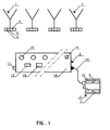
- the glasses 1 are equipped with a light source polychromatic 4, a battery 5 and an organ 6 of the polychromatic source 4. further include a circuitry electronic devices, not shown, among which circuit for controlling the battery charge and a memory associated with the actuating member 6 and intended to contain an operating program for the maneuver and the piloting this actuator.
- the control module 3 comprises a charger of battery 7, a programmer 8 and a marking member 9 glasses 1 and tray 18.
- the programmer 8 includes a list of pre-established programs and preregistered.
- a switch 15 makes it possible to select to choose an operating program from this list of pre-recorded programs.
- An electrical connection removable 10 allows to connect the module 3 to the plate 18.
- the plate 18 includes a socket 11 for the connect to the electricity supply network, electric induction loops 12, a battery 13, a memory 19 and a switch 14.
- the number of induction loops 12 is generally equal to the number of glasses 1, although this is not not essential.
- the glasses 1 are placed on the plateau 18, with their respective bases above the induction loops 12, the switch 14 is positioned on the mode 'charge' and connects the socket 11 to the network electric.
- the switch 14 is positioned on the mode 'charge' and connects the socket 11 to the network electric.
- the marking member 9 is connected to the plate 18 to assign to the glasses 1 and the tray 18 a code identification by means of the marking member 9.
- auxiliary step which follows the operation of marking of the first step, we operate a switch 15 of the control module 3, to select a operating program from the aforementioned list of programs prerecorded and that one sends to the tray 18 which the put in memory.
- a second step following the first step and the auxiliary step, we operate the switch 14 of the tray 18 to place it in a position for which the operating program selected at the auxiliary step aforesaid is transferred to the memory of the organ actuating 6 glasses 1.
- the light source 4 of the glasses 1 adopts a behavior imposed by the actuating member 6, which acts in response to an instruction of the operating program of his memory (The light source 4 emits for example a light monochromatic in a defined range of frequencies and with a defined intensity).
- the plate 18 and the glasses 1 are then ready for use in a ceremony.
- the plug is disconnected 11 of the electrical network and, at that moment, the light emitted by the glasses changes by action of the organ actuator 6, driven by the operating program of his memory.
- the plate 18 is circulated among participants of the ceremony (eg guests, in the case of a festive ceremony), way that they remove a glass from the tray, in turn role. As soon as a glass leaves the tray, the frequency of the light it emits changes, by action of the organ actuator 6, driven by the operating program of his memory.
- the frequency or the intensity of the light source 4 of the glasses changes in response to the variation of one or more parameters particular, such as, for example, the flow of time, the position of the glass with respect to reference (eg electromagnetic terminals) or lighting of the premises (non-exhaustive list).
- a fifth step corresponding to the delivery of the glass 1 on the plate 18, the frequency of its source of light will change again, to adopt a value to distinguish between him (glass rested on the tray 18 after use) and the full glasses lying on the board and not having still been used.
- a sixth step is the washing of the glasses, the outcome of the reception.
- the actuating member 6 cuts the electrical connection from its battery to its source of light.
- Programming (the operating program of the memory of the actuating device 6) furthermore an incidental step, between the third and the fourth stage, which corresponds to the case where a glass is placed on the tray, immediately after being removed, without have been consumed.
- the light source adopts a distinctive behavior, for which, for example, the light emitted by its source flashes.
- This accessory step distinguishes two categories of full glasses on tray 18 (the original glasses and those who have already gone through hands of the guests) and it allows to withdraw immediately the second category of glasses on the board.
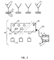
- the glasses 1 are equipped with a wave transceiver 16 and the interface 2 comprises, in addition to the plateau 18, beacons 17 each equipped with a transceiver of radio waves.
- the tags 17 of the interface 2 are dispersed in the environment where the ceremony is held be, for example, a room or an outdoor space). They are designed and programmed to interact with transceivers 16 of the glasses 1 and with the programmer 8 of the control module 3. For this purpose, they are connected to the control module 3 by a wiring electric or by radio waves. In the case of a radio wave link, the control 3 is equipped with a wave transceiver radio signals (not shown) and beacons 17 include an electric battery or are connected to the electrical distribution network.
- the plate 18 When using the installation of the figure 2, the plate 18 is used to mark the glasses 1, the tray 18 and beacons 17, as well as charging the batteries 5 and 13 and possibly those of the beacons 17.
- the transfer of the operating program into the memory of the actuating member 6 of the glasses 1 from the prerecorded programs of the programmer 8 is realized via the induction loops of the board 18 or by waves between the transceivers of the beacons 17 and the transceivers 16 of the glasses 1.
- the or each tag 17 sends its instructions to transceivers 16 of the glasses 1, according to an order predetermined logic.
- the information received is interpreted by the operating program of glasses 1 which will control the actuating member 6 of each glass in function of instructions from the pre-recorded program that has been selected in the programmer 8.
- the operating program of a glasses 1 will calculate the position of said glass relative to the beacons 17 and control the actuator of its light source according to the instructions of the tags and instructions of the pre-recorded program selected and stored in its memory.
- the transceiver 16 of each glass 1 is normally swept by a succession of radio signals that are emitted successively by the beacon transceivers 17, according to a predetermined logical order.
- the mode of most appropriate scan will depend on the circumstances local authorities and the means to implement it can be determined in each particular case by a man of job.
- the pre-recorded programs of the programmer 8 include a spatialization table and / or a topography table.
- the spatialization table has a series of parameters which are selectively activated to drive the organ actuating 6 glasses 1, in response to signals radio signals emitted by the transceivers of beacons 17 and received by transceivers 16 of glasses 1 and analyzed to determine, among other things, spatial coordinates of these. Under the effect of this control, the frequency and / or the intensity of the light glasses will change according to the coordinates relative spatial values of glasses.
- the topography table has a series of parameters that are enabled selectively for controlling the actuating member 6 of the glasses 1, in response to radio signals transmitted by the transceivers 17 and received by the transceivers 16 of the glasses 1 and relating to information related to the topography of the places, such as obstacles to the normal spread of participants in the environment where the ceremony is being held.
- These obstacles can for example include different levels or floors of a building, walls, stairs, inclined planes, low ceilings, statues or other decorations, bins of plants, water basins, fountains, etc.
- the beacons 17 of interface 2 can be fixed. This form of realization of the installation allows in particular glasses users to identify their position in a space, by color vision or information appearing on their glass.
- the tags 17 of interface 2 or some of them can be mobile. For example, we can imagine that some participants of a ceremony bear a marker 17, which will trace them, by vision of the color of the light of the glasses of the other participants located in their immediate vicinity.
Landscapes
- Toys (AREA)
- Detergent Compositions (AREA)
- Drying Of Solid Materials (AREA)
- Management, Administration, Business Operations System, And Electronic Commerce (AREA)
- Circuit Arrangement For Electric Light Sources In General (AREA)
Priority Applications (17)
| Application Number | Priority Date | Filing Date | Title |
|---|---|---|---|
| EP04007919A EP1583401A1 (de) | 2004-04-01 | 2004-04-01 | Zeremonielle Vorrichtung |
| AT05731856T ATE400983T1 (de) | 2004-04-01 | 2005-03-31 | Zeremonielle installation |
| CA002561439A CA2561439A1 (fr) | 2004-04-01 | 2005-03-31 | Installation ceremonielle |
| JP2007505343A JP2007530180A (ja) | 2004-04-01 | 2005-03-31 | 儀式用設備 |
| US11/547,163 US8124948B2 (en) | 2004-04-01 | 2005-03-31 | Ceremonial installation |
| PT05731856T PT1733597E (pt) | 2004-04-01 | 2005-03-31 | Instalação cerimonial |
| DK05731856T DK1733597T3 (da) | 2004-04-01 | 2005-03-31 | Ceremoniel installation |
| BRPI0509550-6A BRPI0509550A (pt) | 2004-04-01 | 2005-03-31 | instalação cerimonial |
| PCT/BE2005/000044 WO2005096676A1 (fr) | 2004-04-01 | 2005-03-31 | Installation ceremonielle |
| EP05731856A EP1733597B1 (de) | 2004-04-01 | 2005-03-31 | Zeremonielle installation |
| ES05731856T ES2310818T3 (es) | 2004-04-01 | 2005-03-31 | Instalacion ceremonial. |
| DE602005008026T DE602005008026D1 (de) | 2004-04-01 | 2005-03-31 | Zeremonielle installation |
| CNA200580011612XA CN1973581A (zh) | 2004-04-01 | 2005-03-31 | 仪式的设施 |
| AU2005227523A AU2005227523B2 (en) | 2004-04-01 | 2005-03-31 | Ceremonial installation |
| PL05731856T PL1733597T3 (pl) | 2004-04-01 | 2005-03-31 | Instalacja do stosowania podczas uroczystości |
| HK07106027.7A HK1101006B (en) | 2004-04-01 | 2005-03-31 | Ceremonial installation |
| IL178408A IL178408A (en) | 2004-04-01 | 2006-09-28 | Ceremonial installation |
Applications Claiming Priority (1)
| Application Number | Priority Date | Filing Date | Title |
|---|---|---|---|
| EP04007919A EP1583401A1 (de) | 2004-04-01 | 2004-04-01 | Zeremonielle Vorrichtung |
Publications (1)
| Publication Number | Publication Date |
|---|---|
| EP1583401A1 true EP1583401A1 (de) | 2005-10-05 |
Family
ID=34878231
Family Applications (2)
| Application Number | Title | Priority Date | Filing Date |
|---|---|---|---|
| EP04007919A Withdrawn EP1583401A1 (de) | 2004-04-01 | 2004-04-01 | Zeremonielle Vorrichtung |
| EP05731856A Expired - Lifetime EP1733597B1 (de) | 2004-04-01 | 2005-03-31 | Zeremonielle installation |
Family Applications After (1)
| Application Number | Title | Priority Date | Filing Date |
|---|---|---|---|
| EP05731856A Expired - Lifetime EP1733597B1 (de) | 2004-04-01 | 2005-03-31 | Zeremonielle installation |
Country Status (15)
| Country | Link |
|---|---|
| US (1) | US8124948B2 (de) |
| EP (2) | EP1583401A1 (de) |
| JP (1) | JP2007530180A (de) |
| CN (1) | CN1973581A (de) |
| AT (1) | ATE400983T1 (de) |
| AU (1) | AU2005227523B2 (de) |
| BR (1) | BRPI0509550A (de) |
| CA (1) | CA2561439A1 (de) |
| DE (1) | DE602005008026D1 (de) |
| DK (1) | DK1733597T3 (de) |
| ES (1) | ES2310818T3 (de) |
| IL (1) | IL178408A (de) |
| PL (1) | PL1733597T3 (de) |
| PT (1) | PT1733597E (de) |
| WO (1) | WO2005096676A1 (de) |
Cited By (1)
| Publication number | Priority date | Publication date | Assignee | Title |
|---|---|---|---|---|
| WO2007102112A1 (en) * | 2006-03-06 | 2007-09-13 | Koninklijke Philips Electronics N.V. | Use of decision trees for automatic commissioning. |
Families Citing this family (1)
| Publication number | Priority date | Publication date | Assignee | Title |
|---|---|---|---|---|
| US10306419B2 (en) | 2017-09-29 | 2019-05-28 | Abl Ip Holding Llc | Device locating using angle of arrival measurements |
Citations (13)
| Publication number | Priority date | Publication date | Assignee | Title |
|---|---|---|---|---|
| US3737647A (en) | 1971-04-16 | 1973-06-05 | Chiyoda Kk | Electronic luminous device |
| US4344113A (en) | 1979-12-18 | 1982-08-10 | Donald R. Ditto | Apparatus to illuminate a liquid drink |
| GB2135536A (en) | 1982-12-24 | 1984-08-30 | Wobbot International Limited | Sound responsive lighting system and devices incorporating same |
| US5339548A (en) | 1992-08-26 | 1994-08-23 | Russell James M | Receptacle display activated after the sensing of the condition of the liquid |
| US6163248A (en) * | 1998-03-06 | 2000-12-19 | Paek; Seung-Mok | Cup luminous apparatus and its control method |
| FR2807281A1 (fr) | 2000-03-29 | 2001-10-05 | Christophe Mermaz | Articles lumineux jetables, notamment verres et autres articles pour la fete ou autres applications |
| FR2807282A1 (fr) | 2000-03-29 | 2001-10-05 | Christophe Mermaz | Articles a dispositif lumineux incorpore, notamment verres et autres articles pour la fete ou autres, d'esthetique "haut de gamme", et le dispositif correspondant |
| US20020047646A1 (en) * | 1997-08-26 | 2002-04-25 | Ihor Lys | Lighting entertainment system |
| US20020068544A1 (en) * | 2000-12-01 | 2002-06-06 | Ziv Barzilay | Method and system for remotely controlling a plurality of electrical switches |
| US6430064B1 (en) * | 2001-06-29 | 2002-08-06 | Aichi Electric Co. Ltd. | Non-contact power supply device |
| DE10138063A1 (de) * | 2001-08-03 | 2003-02-27 | Helmut Bucksch | Trinkgefäß mit einer Vorrichtung zur Anzeige der Trinkmenge |
| WO2003026358A1 (en) * | 2001-09-17 | 2003-03-27 | Color Kinetics Incorporated | Light emitting diode based products |
| WO2003067934A2 (en) * | 2002-02-06 | 2003-08-14 | Color Kinetics Incorporated | Controlled lighting methods and apparatus |
Family Cites Families (3)
| Publication number | Priority date | Publication date | Assignee | Title |
|---|---|---|---|---|
| US4980806A (en) * | 1986-07-17 | 1990-12-25 | Vari-Lite, Inc. | Computer controlled lighting system with distributed processing |
| CA1293989C (en) * | 1986-07-17 | 1992-01-07 | Brooks W. Taylor | Computer controlled lighting system with distributed processing |
| US5307295A (en) * | 1991-01-14 | 1994-04-26 | Vari-Lite, Inc. | Creating and controlling lighting designs |
-
2004
- 2004-04-01 EP EP04007919A patent/EP1583401A1/de not_active Withdrawn
-
2005
- 2005-03-31 PL PL05731856T patent/PL1733597T3/pl unknown
- 2005-03-31 WO PCT/BE2005/000044 patent/WO2005096676A1/fr not_active Ceased
- 2005-03-31 DK DK05731856T patent/DK1733597T3/da active
- 2005-03-31 JP JP2007505343A patent/JP2007530180A/ja active Pending
- 2005-03-31 PT PT05731856T patent/PT1733597E/pt unknown
- 2005-03-31 CN CNA200580011612XA patent/CN1973581A/zh active Pending
- 2005-03-31 EP EP05731856A patent/EP1733597B1/de not_active Expired - Lifetime
- 2005-03-31 BR BRPI0509550-6A patent/BRPI0509550A/pt not_active IP Right Cessation
- 2005-03-31 US US11/547,163 patent/US8124948B2/en not_active Expired - Fee Related
- 2005-03-31 DE DE602005008026T patent/DE602005008026D1/de not_active Expired - Lifetime
- 2005-03-31 ES ES05731856T patent/ES2310818T3/es not_active Expired - Lifetime
- 2005-03-31 CA CA002561439A patent/CA2561439A1/fr not_active Abandoned
- 2005-03-31 AT AT05731856T patent/ATE400983T1/de active
- 2005-03-31 AU AU2005227523A patent/AU2005227523B2/en not_active Ceased
-
2006
- 2006-09-28 IL IL178408A patent/IL178408A/en not_active IP Right Cessation
Patent Citations (13)
| Publication number | Priority date | Publication date | Assignee | Title |
|---|---|---|---|---|
| US3737647A (en) | 1971-04-16 | 1973-06-05 | Chiyoda Kk | Electronic luminous device |
| US4344113A (en) | 1979-12-18 | 1982-08-10 | Donald R. Ditto | Apparatus to illuminate a liquid drink |
| GB2135536A (en) | 1982-12-24 | 1984-08-30 | Wobbot International Limited | Sound responsive lighting system and devices incorporating same |
| US5339548A (en) | 1992-08-26 | 1994-08-23 | Russell James M | Receptacle display activated after the sensing of the condition of the liquid |
| US20020047646A1 (en) * | 1997-08-26 | 2002-04-25 | Ihor Lys | Lighting entertainment system |
| US6163248A (en) * | 1998-03-06 | 2000-12-19 | Paek; Seung-Mok | Cup luminous apparatus and its control method |
| FR2807282A1 (fr) | 2000-03-29 | 2001-10-05 | Christophe Mermaz | Articles a dispositif lumineux incorpore, notamment verres et autres articles pour la fete ou autres, d'esthetique "haut de gamme", et le dispositif correspondant |
| FR2807281A1 (fr) | 2000-03-29 | 2001-10-05 | Christophe Mermaz | Articles lumineux jetables, notamment verres et autres articles pour la fete ou autres applications |
| US20020068544A1 (en) * | 2000-12-01 | 2002-06-06 | Ziv Barzilay | Method and system for remotely controlling a plurality of electrical switches |
| US6430064B1 (en) * | 2001-06-29 | 2002-08-06 | Aichi Electric Co. Ltd. | Non-contact power supply device |
| DE10138063A1 (de) * | 2001-08-03 | 2003-02-27 | Helmut Bucksch | Trinkgefäß mit einer Vorrichtung zur Anzeige der Trinkmenge |
| WO2003026358A1 (en) * | 2001-09-17 | 2003-03-27 | Color Kinetics Incorporated | Light emitting diode based products |
| WO2003067934A2 (en) * | 2002-02-06 | 2003-08-14 | Color Kinetics Incorporated | Controlled lighting methods and apparatus |
Cited By (2)
| Publication number | Priority date | Publication date | Assignee | Title |
|---|---|---|---|---|
| WO2007102112A1 (en) * | 2006-03-06 | 2007-09-13 | Koninklijke Philips Electronics N.V. | Use of decision trees for automatic commissioning. |
| US8416713B2 (en) | 2006-03-06 | 2013-04-09 | Koninklijke Philips Electronics N.V. | Use of decision trees for automatic commissioning |
Also Published As
| Publication number | Publication date |
|---|---|
| IL178408A0 (en) | 2007-02-11 |
| DE602005008026D1 (de) | 2008-08-21 |
| BRPI0509550A (pt) | 2007-09-18 |
| AU2005227523A1 (en) | 2005-10-13 |
| AU2005227523B2 (en) | 2011-01-06 |
| US20070272879A1 (en) | 2007-11-29 |
| IL178408A (en) | 2010-05-17 |
| ES2310818T3 (es) | 2009-01-16 |
| PL1733597T3 (pl) | 2009-01-30 |
| CN1973581A (zh) | 2007-05-30 |
| ATE400983T1 (de) | 2008-07-15 |
| JP2007530180A (ja) | 2007-11-01 |
| PT1733597E (pt) | 2008-10-16 |
| CA2561439A1 (fr) | 2005-10-13 |
| WO2005096676A1 (fr) | 2005-10-13 |
| HK1101006A1 (zh) | 2007-10-05 |
| EP1733597B1 (de) | 2008-07-09 |
| EP1733597A1 (de) | 2006-12-20 |
| US8124948B2 (en) | 2012-02-28 |
| DK1733597T3 (da) | 2008-10-20 |
Similar Documents
| Publication | Publication Date | Title |
|---|---|---|
| US12562584B2 (en) | System and method for charging and updating electronic candles | |
| CN105874728B (zh) | 信息通信方法及信息通信装置 | |
| EP3527105B1 (de) | Kompakter spiegel | |
| EP2293414A2 (de) | Vorrichtung zum Abkoppeln mindestens eines Geräts vom Stromnetz, die mindestens einen Ausnahmefunktionsmodus anbietet, konfigurierbare Vorrichtung sowie Konfigurationssystem und -verfahren | |
| EP3254443B1 (de) | Kommunikationssystem und kommunikationsverfahren mit dem einsatz von einem behälter fur schönheitsmittel, medikament, wein, oder alkoholisches getränk zusammen mit zwei mobilen kommunikationsendgeräten | |
| WO2015121433A1 (fr) | Lampe electrique portative dotee d'un systeme de communication sans fil | |
| JP2009187951A (ja) | 発光ダイオードに基づく製品 | |
| CN104871455B (zh) | 信息通信方法 | |
| FR2628335A1 (fr) | Installation pour assurer la regie du son, de la lumiere et/ou d'autres effets physiques d'un spectacle | |
| EP1733597B1 (de) | Zeremonielle installation | |
| EP0495322A1 (de) | Elektrisches Kontroll- und Steuerungssystem einer Funktionseinheit, insbesondere eines Hauses eines Gebäudes, eines Schiffes oder dergleichen | |
| EP3840165A1 (de) | Ladegestell für flammenlose kerzen | |
| US11602233B2 (en) | Digital shadow box | |
| HK1101006B (en) | Ceremonial installation | |
| FR2991545A1 (fr) | Dispositif et procede de pilotage de peripherique luminaire par programme de controle importe | |
| EP3573345B1 (de) | Verbundenes objekt, das mit einem funkkommunikationsmittel und einem bordmikrofon versehen ist, das in mindestens zwei stabilen positionen platziert werden kann | |
| CN210747823U (zh) | 一种智能镜 | |
| WO2008043889A1 (fr) | Luminaire comprenant au moins un moyen d'eclairage dont l'activation s'effectue par l'emission d'un rayonnement lumineux | |
| FR3050299A1 (fr) | Dispositif electrique communiquant par ultrasons et procede de controle d'un systeme comprenant un tel dispositif electrique | |
| WO2017198604A1 (en) | System for the ritual and gestural lighting of electrical or electronic light sources | |
| FR2718827A1 (fr) | Procédé d'illumination d'objets. | |
| WO2014016503A2 (fr) | Appairage de dispositifs | |
| WO2002082860A2 (fr) | Procede et systeme pour diffuser selectivement des informations dans un espace, et equipements mis en oeuvre dans ce systeme | |
| EP2107802A1 (de) | Steuervorrichtung für mehrere Geräte mit Hilfe einer Infrarot-Fernsteuerung |
Legal Events
| Date | Code | Title | Description |
|---|---|---|---|
| PUAI | Public reference made under article 153(3) epc to a published international application that has entered the european phase |
Free format text: ORIGINAL CODE: 0009012 |
|
| AK | Designated contracting states |
Kind code of ref document: A1 Designated state(s): AT BE BG CH CY CZ DE DK EE ES FI FR GB GR HU IE IT LI LU MC NL PL PT RO SE SI SK TR |
|
| AX | Request for extension of the european patent |
Extension state: AL HR LT LV MK |
|
| AKX | Designation fees paid | ||
| REG | Reference to a national code |
Ref country code: DE Ref legal event code: 8566 |
|
| STAA | Information on the status of an ep patent application or granted ep patent |
Free format text: STATUS: THE APPLICATION IS DEEMED TO BE WITHDRAWN |
|
| 18D | Application deemed to be withdrawn |
Effective date: 20060406 |