EP1583633B1 - Procede et dispositif de percage laser dans une atmosphere de gaz de traitement - Google Patents
Procede et dispositif de percage laser dans une atmosphere de gaz de traitement Download PDFInfo
- Publication number
- EP1583633B1 EP1583633B1 EP03779697A EP03779697A EP1583633B1 EP 1583633 B1 EP1583633 B1 EP 1583633B1 EP 03779697 A EP03779697 A EP 03779697A EP 03779697 A EP03779697 A EP 03779697A EP 1583633 B1 EP1583633 B1 EP 1583633B1
- Authority
- EP
- European Patent Office
- Prior art keywords
- laser beam
- process gas
- workpiece
- outlet opening
- backing
- Prior art date
- Legal status (The legal status is an assumption and is not a legal conclusion. Google has not performed a legal analysis and makes no representation as to the accuracy of the status listed.)
- Expired - Lifetime
Links
Images


Classifications
-
- B—PERFORMING OPERATIONS; TRANSPORTING
- B23—MACHINE TOOLS; METAL-WORKING NOT OTHERWISE PROVIDED FOR
- B23K—SOLDERING OR UNSOLDERING; WELDING; CLADDING OR PLATING BY SOLDERING OR WELDING; CUTTING BY APPLYING HEAT LOCALLY, e.g. FLAME CUTTING; WORKING BY LASER BEAM
- B23K26/00—Working by laser beam, e.g. welding, cutting or boring
- B23K26/12—Working by laser beam, e.g. welding, cutting or boring in a special environment or atmosphere, e.g. in an enclosure
- B23K26/123—Working by laser beam, e.g. welding, cutting or boring in a special environment or atmosphere, e.g. in an enclosure in an atmosphere of particular gases
-
- B—PERFORMING OPERATIONS; TRANSPORTING
- B23—MACHINE TOOLS; METAL-WORKING NOT OTHERWISE PROVIDED FOR
- B23K—SOLDERING OR UNSOLDERING; WELDING; CLADDING OR PLATING BY SOLDERING OR WELDING; CUTTING BY APPLYING HEAT LOCALLY, e.g. FLAME CUTTING; WORKING BY LASER BEAM
- B23K26/00—Working by laser beam, e.g. welding, cutting or boring
- B23K26/009—Working by laser beam, e.g. welding, cutting or boring using a non-absorbing, e.g. transparent, reflective or refractive, layer on the workpiece
-
- B—PERFORMING OPERATIONS; TRANSPORTING
- B23—MACHINE TOOLS; METAL-WORKING NOT OTHERWISE PROVIDED FOR
- B23K—SOLDERING OR UNSOLDERING; WELDING; CLADDING OR PLATING BY SOLDERING OR WELDING; CUTTING BY APPLYING HEAT LOCALLY, e.g. FLAME CUTTING; WORKING BY LASER BEAM
- B23K26/00—Working by laser beam, e.g. welding, cutting or boring
- B23K26/14—Working by laser beam, e.g. welding, cutting or boring using a fluid stream, e.g. a jet of gas, in conjunction with the laser beam; Nozzles therefor
- B23K26/1435—Working by laser beam, e.g. welding, cutting or boring using a fluid stream, e.g. a jet of gas, in conjunction with the laser beam; Nozzles therefor involving specially adapted flow-control means
- B23K26/1436—Working by laser beam, e.g. welding, cutting or boring using a fluid stream, e.g. a jet of gas, in conjunction with the laser beam; Nozzles therefor involving specially adapted flow-control means for pressure control
-
- B—PERFORMING OPERATIONS; TRANSPORTING
- B23—MACHINE TOOLS; METAL-WORKING NOT OTHERWISE PROVIDED FOR
- B23K—SOLDERING OR UNSOLDERING; WELDING; CLADDING OR PLATING BY SOLDERING OR WELDING; CUTTING BY APPLYING HEAT LOCALLY, e.g. FLAME CUTTING; WORKING BY LASER BEAM
- B23K26/00—Working by laser beam, e.g. welding, cutting or boring
- B23K26/14—Working by laser beam, e.g. welding, cutting or boring using a fluid stream, e.g. a jet of gas, in conjunction with the laser beam; Nozzles therefor
- B23K26/1435—Working by laser beam, e.g. welding, cutting or boring using a fluid stream, e.g. a jet of gas, in conjunction with the laser beam; Nozzles therefor involving specially adapted flow-control means
- B23K26/1438—Working by laser beam, e.g. welding, cutting or boring using a fluid stream, e.g. a jet of gas, in conjunction with the laser beam; Nozzles therefor involving specially adapted flow-control means for directional control
-
- B—PERFORMING OPERATIONS; TRANSPORTING
- B23—MACHINE TOOLS; METAL-WORKING NOT OTHERWISE PROVIDED FOR
- B23K—SOLDERING OR UNSOLDERING; WELDING; CLADDING OR PLATING BY SOLDERING OR WELDING; CUTTING BY APPLYING HEAT LOCALLY, e.g. FLAME CUTTING; WORKING BY LASER BEAM
- B23K26/00—Working by laser beam, e.g. welding, cutting or boring
- B23K26/14—Working by laser beam, e.g. welding, cutting or boring using a fluid stream, e.g. a jet of gas, in conjunction with the laser beam; Nozzles therefor
- B23K26/1462—Nozzles; Features related to nozzles
-
- B—PERFORMING OPERATIONS; TRANSPORTING
- B23—MACHINE TOOLS; METAL-WORKING NOT OTHERWISE PROVIDED FOR
- B23K—SOLDERING OR UNSOLDERING; WELDING; CLADDING OR PLATING BY SOLDERING OR WELDING; CUTTING BY APPLYING HEAT LOCALLY, e.g. FLAME CUTTING; WORKING BY LASER BEAM
- B23K26/00—Working by laser beam, e.g. welding, cutting or boring
- B23K26/18—Working by laser beam, e.g. welding, cutting or boring using absorbing layers on the workpiece, e.g. for marking or protecting purposes
-
- B—PERFORMING OPERATIONS; TRANSPORTING
- B23—MACHINE TOOLS; METAL-WORKING NOT OTHERWISE PROVIDED FOR
- B23K—SOLDERING OR UNSOLDERING; WELDING; CLADDING OR PLATING BY SOLDERING OR WELDING; CUTTING BY APPLYING HEAT LOCALLY, e.g. FLAME CUTTING; WORKING BY LASER BEAM
- B23K26/00—Working by laser beam, e.g. welding, cutting or boring
- B23K26/36—Removing material
- B23K26/38—Removing material by boring or cutting
- B23K26/382—Removing material by boring or cutting by boring
-
- B—PERFORMING OPERATIONS; TRANSPORTING
- B23—MACHINE TOOLS; METAL-WORKING NOT OTHERWISE PROVIDED FOR
- B23K—SOLDERING OR UNSOLDERING; WELDING; CLADDING OR PLATING BY SOLDERING OR WELDING; CUTTING BY APPLYING HEAT LOCALLY, e.g. FLAME CUTTING; WORKING BY LASER BEAM
- B23K26/00—Working by laser beam, e.g. welding, cutting or boring
- B23K26/36—Removing material
- B23K26/38—Removing material by boring or cutting
- B23K26/382—Removing material by boring or cutting by boring
- B23K26/389—Removing material by boring or cutting by boring of fluid openings, e.g. nozzles, jets
-
- B—PERFORMING OPERATIONS; TRANSPORTING
- B23—MACHINE TOOLS; METAL-WORKING NOT OTHERWISE PROVIDED FOR
- B23K—SOLDERING OR UNSOLDERING; WELDING; CLADDING OR PLATING BY SOLDERING OR WELDING; CUTTING BY APPLYING HEAT LOCALLY, e.g. FLAME CUTTING; WORKING BY LASER BEAM
- B23K26/00—Working by laser beam, e.g. welding, cutting or boring
- B23K26/36—Removing material
- B23K26/40—Removing material taking account of the properties of the material involved
-
- B—PERFORMING OPERATIONS; TRANSPORTING
- B23—MACHINE TOOLS; METAL-WORKING NOT OTHERWISE PROVIDED FOR
- B23K—SOLDERING OR UNSOLDERING; WELDING; CLADDING OR PLATING BY SOLDERING OR WELDING; CUTTING BY APPLYING HEAT LOCALLY, e.g. FLAME CUTTING; WORKING BY LASER BEAM
- B23K2103/00—Materials to be soldered, welded or cut
- B23K2103/50—Inorganic materials other than metals or composite materials
Definitions
- the present invention relates to a method for laser drilling according to the preamble of patent claim 1 and a corresponding device according to the preamble of claim 8 (see, eg. US-A-6 070 813 ).
- precision mini-holes are conventionally introduced by means of erosion processes.
- minimum diameters of about 120 ⁇ m can currently be produced in large series.
- laser drilling enables the production of precision holes with diameters smaller than 120 ⁇ m, but has not yet been introduced as a large-scale production process.
- a laser beam performs a wobbling motion relative to a workpiece. This ensures that a conical surface is traversed within the workpiece. The polarization plane of the laser beam is thereby rotated synchronously with the tumbling motion.
- a method of introducing a microhole into a workpiece by means of a laser beam is disclosed.
- the focus of the laser beam is continuously moved along a concentric circular path to the hole axis, wherein the laser beam is composed of a sequence of short laser pulses.
- HE hydroerosive
- the course of the exit of the bore is to be influenced in a targeted manner.
- a region of a component is exposed to a laser beam, a hole being produced within this region.
- This admission or bore is carried out under an adjustable process gas atmosphere. Due to an interaction between the laser beam used and the selected process gas within the area acted upon by the laser beam or hole plasma is formed by ionization of the process gas.
- the invention provides that a tiltable backing is arranged on an outlet opening of the hole produced by the laser beam.
- the process gas or gas mixture used according to the invention serves primarily to increase the quality of the processing and to optimize the processing time, in particular to shorten the processing time.
- the creation of special process atmospheres indirectly influences the laser beam-matter interaction in the applied area or hole and thus the processing process.
- the type of process gas atmosphere determines the properties of the plasmas forming according to the invention in the interaction with the laser radiation used with the material or material to be processed, wherein the plasma formation is supported by material vapor.
- a laser for example, a solid-state laser (Nd: YAG) is used.
- Different process gases each generate plasmas, which are z. B. can differ in their temperature and expansion.
- the process time of HE rounding can be significantly reduced, or that HE rounds is no longer necessary.
- fuel inlets can be designed in a way that does not allow HE rounding.
- asymmetrical fillets can be introduced by the method according to the invention or symmetrical or asymmetrical bulges can be generated shortly after the fuel inlet. Fillets have the advantage of improved inflow behavior while bulges can be used to prevent turbulence, which may occur at the fuel inlet, or to produce targeted.
- the plasma state shortly before and during the re-emergence of the laser beam from the material.
- fillets, bulges and / or sharp exit edges may form, which may be rotationally symmetric uniform over the entire borehole exit, or the phenomena may occur only on one side.
- backings have the task of preventing free propagation of the laser beam after its re-emergence from the material or material. This may conventionally serve to protect another workpiece or parts or areas of the same workpiece from damage. In addition, such backings may maintain the condition of a closed well for a certain time and thus help to create an exit orifice as desired.
- Backing can influence the formation of a borehole outlet by reflecting the incoming laser radiation back towards the material or by influencing the plasma ionized from the process gas in its propagation, thus leading to further material removal.
- Another influence can be a plasma, which may be caused by the removal of the backing.
- an inert gas such as nitrogen is suitably used as the process gas, in particular with the addition of noble gases such as helium, argon and the like.
- the use of such a process gas has the advantage that a region to be acted becomes inert, so that oxidation of this region is avoided.
- by such a composition of the process gas ensures that sufficient bore surface qualities and melt film thicknesses are ensured.
- the process gas is pressurized, wherein the pressure is preferably set below about 1.5 bar. This promotes the formation of bulges in the holes produced. It is also possible to choose higher pressures, which can suppress bulges.
- the pressures used according to the invention lead to bulging phenomena in the vicinity of the edge region of the workpiece to be machined. The higher the pressure used, the deeper a Ausbauchom moves into the interior of the workpiece.
- the angle of tilting can in this case in particular be between 0 ° and 15 °.
- the ionization of the process gas can, apart from the prevailing conditions of introduction of the process gas (composition, pressure, direction), in particular be influenced by properties of the laser beam such as wavelength and power.
- a backing used in this case can have thermal or optical properties which influence the shape or design of the outlet opening.
- it is provided here to provide suitable metallic materials, in particular copper. These material properties are particularly important for the degree of expansion of the outlet opening of importance. For example, at laser wavelengths of 1064 .mu.m and a backing made of copper arranged at a suitable distance from the outlet opening, relatively large expansions are formed, whereas in the case of a backing made of steel relatively small widenings occur.
- the geometry of the backing can influence the shape or design of the outlet opening. According to the invention, the use of copper as backing material is particularly preferred.
- the backing in an influencing the shape of the outlet opening distance to arrange the outlet opening.
- Such a distance is preferably selected between 20 ⁇ m to 200 ⁇ m.
- the geometry of the expansion of the borehole outlet can be influenced in a simple manner.
- the backing is, according to the invention, arranged by tilting relative to the outlet opening at a predetermined angle. Differently strongly selected tiltings in this case produce differently asymmetrical widening of the outlet opening of the borehole. Preferred angles used here are between 0 ° and 20 °.
- asymmetric rounding be introduced in a region of the outlet opening of a hole in a simple manner, which has the advantage that a subsequent HE rounding is no longer required or only to a limited extent.
- the device according to the invention is characterized in that it comprises a laser beam, a holding device for a component to be processed and means for adjusting a process gas atmosphere.
- As means for adjusting the process gas atmosphere may preferably be provided at least one gas nozzle. This allows flowing process gas of suitable composition to be controlled in a manner which is easy to control under suitable pressure and at a suitable angle directing area of a workpiece directable.
- a suitable composition of the process gas may be provided by a gas mixer.
- a backing is positioned on an outlet opening produced on the component by the action of the laser beam.
- FIG. 1 the illustrated embodiment of the device according to the invention is generally designated 100.
- a laser beam 30 generated by a laser 31 The laser beam 30 is partially reflected or switched on a shutter 34, in which case scattered or excess residual radiation is absorbed by a jet sump 33.
- the direction of the laser beam 30 is deflected within its beam path by one or more mirrors 37.
- a trephining optics 35 is also arranged within the beam path, and the device for focusing the laser beam also has a focusing lens 36.
- the beam path of the laser beam 30 passes through a gas nozzle 12 and strikes a workpiece 40 to be machined.
- the process gas required for carrying out the method according to the invention is provided by a gas mixer 11 and added to a gas nozzle 12 via a line 11a.
- the process gas is blown directly onto the workpiece 40 with the aid of the gas nozzle 12.
- the workpiece 40 is mounted in a handle 50.
- This handling 50 can be moved by suitable measures in all three spatial directions x, y or z, so that a suitable for carrying out the method positioning of the workpiece 40 is adjustable.
- the laser beam 30 can be varied in its focus position.
- the gas nozzle 12 can be positioned relative to the direction of the beam path of the laser beam 30 passing through the gas nozzle 12 or to the workpiece 40. In this case, a movement takes place along the direction x or y.
- a rotation of the gas nozzle 12 can be realized by means of a suitable mechanism, wherein such pivotability in FIG. 1 is symbolized with ⁇ .
- the method according to the invention for laser drilling can be realized in a simple manner.
- the laser beam 30, after its beam path has passed through the gas nozzle 12, strikes the workpiece 40.
- the ionization of process gas to plasma by the interaction between the process gas and the laser beam 30 within the Beauftschungs Kunststoffes favored hereby.
- FIG. 2 is a detail from FIG. 1 shown.
- the workpiece 40 is according to the invention via a holder 51 relative to the handling 50 fixed positionable, wherein a suitable position of the workpiece 40 relative to the handling 50 via the holder 51 is adjustable by movement.
- a backing 20 is fixedly positionable relative to the handle 50 by means of a holder 52, wherein a suitable position of the backing 20 relative to the handling 50 can be adjusted via the holder 52 by movement.
- the backing 20 and the workpiece 40 can be spatially positioned relative to one another in a desired manner, but this can also be achieved before during the described method.
- a hole 44 to be produced in the workpiece 40 by means of the laser drilling method is formed at the location of the workpiece 40 at which the laser beam 30 impinges on the workpiece 40, the laser beam being incident on an exit opening 43 of the hole 44 on the workpiece Backing 20 facing side of the workpiece 40 exits.
- the process gas blown onto the workpiece 40 at a suitable angle from a suitable gas nozzle, not shown, is ionized by interaction with the laser beam 30 in the region of the hole 44 or a region of the outlet opening 43 by interaction with plasma.
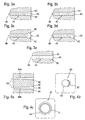
- FIGS. 3a to 3e show detailed views of holes 44 within the workpiece 40 in a cross-sectional view parallel to a bore center axis 46 of the hole 44.
- An unillustrated laser beam 30 was directed from the left parallel to the wellbore center axis 46 on the workpiece 40, piercing the region of its impact the laser beam 30, the workpiece 40, wherein the place of entry into the FIGS. 3a to 3e not shown.
- the respective outlet openings 43 of the holes 44 are in the FIGS. 3a to 3e recognizable.
- a region of the outlet opening 43 of the borehole 44 has a symmetrical expansion 41 or rounding, which by preferably symmetrical arrangement of a backing, not shown.
- the Bohrungsstoffachse 46 within a range behind, in the illustration of FIGS. 3a to 3e right next to, the exit opening 43 was caused.
- the extent of this widening 41 or rounding can be influenced by suitable spacing of the backing relative to the outlet opening 43.
- the widening 41 of a region of the outlet opening 43 of the borehole 44 is asymmetrical or only rounded on one side.
- the method according to the invention was carried out such that the backing was arranged under tilting at a suitable angle to the borehole center axis 46 in a region behind the outlet opening 43.
- Drill hole 44 off Figure 3c see page 12 has symmetrical or bilateral bulges 42 in a region of the outlet opening 43 of the hole 44.
- Such a bulge 42 can be realized, for example, by the described interaction between laser beam and formed plasma.
- Hole 12 shown on page 12 has an asymmetrical bulge 42.
- Such asymmetrical formation of the bulge 42 is facilitated by tilting a nozzle introducing the process gas at a suitable angle relative to the borehole center axis 46 and the laser beam, respectively.
- the borehole 44 is designed such that it has a combination of expansion 41 and bulge 42 in a region of the outlet opening 43.
- Such a design can be achieved by combining the measures described above (tilting of the backing and process gas at an angle).
- FIGS. 4a to 4c Further embodiments of holes 44 produced within a workpiece 40 and produced outlet openings 43 are shown in longitudinal section and in plan view, respectively.
- FIG. 4a see page 12 shows two different shapes of bulges 42 in longitudinal section. Furthermore, by applying the workpiece by a laser beam incident from the left entrance openings 45 are shown, which have a smaller diameter than the outlet openings 43 right.
- the bulge 42 is analogous to 3d figure asymmetric, in the lower hole 44b, however, are analogous to Figure 3c two symmetrical bulges 42 shown.
- outlet opening 43 has an asymmetrical widening 41 or rounding. This was done with appropriate measures, as described with reference to FIG. 3b described, realized. From the same perspective as FIG. 4b shows Figure 4c see page 12 an outlet opening 43 with symmetrical expansion 41 or rounding, which by analogous implementation of the method according to the invention, as with reference to FIG. 3a described, realized.
Landscapes
- Engineering & Computer Science (AREA)
- Physics & Mathematics (AREA)
- Optics & Photonics (AREA)
- Plasma & Fusion (AREA)
- Mechanical Engineering (AREA)
- Laser Beam Processing (AREA)
Claims (9)
- Procédé de perçage par laser, selon lequel une zone d'une pièce à usiner (40) est frappée par un rayon laser (30), pour y former un trou (44),
caractérisé en ce que- le procédé est exécuté sous une atmosphère de gaz de traitement réglable, de façon que, suite à une interaction entre le rayon laser et le gaz de traitement dans la zone du trou (44) frappé par le rayon laser (30), il se forme du plasma,- une contre-pièce (20) est disposée à une ouverture de sortie (43) du trou (44) produite par le rayon laser (30), et- la contre-pièce (20) bascule d'un angle déterminé sur l'ouverture de sortie, et cet angle influence la forme de l'ouverture de sortie (43) et/ou sa disposition dans la pièce à usiner (40). - Procédé selon la revendication 1,
caractérisé en ce qu'
on utilise comme gaz de traitement un gaz inerte, en particulier de l'azote, en particulier avec addition de gaz rares comme l'hélium, l'argon et analogues. - Procédé selon l'une des revendications 1 ou 2,
caractérisé en ce que
le gaz de traitement est mis sous pression, en particulier sous une pression de 1,5 bar au maximum. - Procédé selon l'une des revendications 1 à 3,
caractérisé en ce qu'
on règle la direction d'incidence du gaz de traitement par basculement par rapport à la direction du rayon laser (30), l'angle du basculement pouvant atteindre en particulier 15°. - Procédé selon l'une des revendications 1 à 4,
caractérisé en ce que
la matière utilisée pour la contre-pièce (20), en particulier une matière contenant du cuivre, est choisie pour ses propriétés thermiques et/ou optiques (4) qui influencent la forme de l'ouverture de sortie (43). - Procédé selon l'une des revendications 1 à 5,
caractérisé en ce que
la contre-pièce (20) est disposée à une distance de l'ouverture de sortie (43) et/ou de la pièce à usiner (40) de préférence entre 20 µm et 200 µm, pour influencer la forme de l'ouverture de sortie (43). - Procédé selon l'une des revendications 1 à 6,
caractérisé en ce que
l'angle de basculement de la contre-pièce (20) peut atteindre 20°. - Dispositif de perçage par laser (31) dans lequel un rayon laser (30) frappe une zone d'une pièce à usiner (40) pour produire un trou (44),
caractérisé en ce que
le dispositif présente les caractéristiques suivantes :- des moyens (11, 12) pour régler une atmosphère de gaz de traitement dans la zone et/ou le trou (44) frappé par le rayon laser (30), de façon que, par suite d'une interaction entre le rayon laser (44) et le gaz de traitement, il se forme du plasma dans la zone et/ou le trou (44),- sur l'ouverture de sortie (43) d'un trou (44), on prévoit une contre-pièce (20), positionnable et basculable par rapport à l'ouverture de sortie (43) et/ou la pièce à usiner (40), pour former l'ouverture de sortie (43) ;- on prévoit une fixation (51) pour le positionnement relatif de la pièce à usiner par rapport à un dispositif de maniement (50), et une autre fixation (52) pour le positionnement relatif de la contre-pièce (20), et par la commande des fixations (51, 52), on peut positionner dans l'espace, l'une par rapport à l'autre, de façon voulue, la contre-pièce (20) et la pièce à usiner (40), avant ou pendant le perçage au laser. - Dispositif selon la revendication 8,
caractérisé en ce que
les moyens (11, 12) pour régler l'atmosphère de gaz de traitement présentent au moins une tuyère à gaz (12).
Applications Claiming Priority (3)
| Application Number | Priority Date | Filing Date | Title |
|---|---|---|---|
| DE10300134 | 2003-01-07 | ||
| DE10300134A DE10300134A1 (de) | 2003-01-07 | 2003-01-07 | Verfahren und Vorrichtung zum Laserbohren |
| PCT/DE2003/003801 WO2004060603A1 (fr) | 2003-01-07 | 2003-11-17 | Procede et dispositif de perçage laser dans une atmosphere de gaz de traitement |
Publications (2)
| Publication Number | Publication Date |
|---|---|
| EP1583633A1 EP1583633A1 (fr) | 2005-10-12 |
| EP1583633B1 true EP1583633B1 (fr) | 2008-02-27 |
Family
ID=32519628
Family Applications (1)
| Application Number | Title | Priority Date | Filing Date |
|---|---|---|---|
| EP03779697A Expired - Lifetime EP1583633B1 (fr) | 2003-01-07 | 2003-11-17 | Procede et dispositif de percage laser dans une atmosphere de gaz de traitement |
Country Status (5)
| Country | Link |
|---|---|
| US (1) | US7301121B2 (fr) |
| EP (1) | EP1583633B1 (fr) |
| JP (1) | JP4741243B2 (fr) |
| DE (2) | DE10300134A1 (fr) |
| WO (1) | WO2004060603A1 (fr) |
Families Citing this family (14)
| Publication number | Priority date | Publication date | Assignee | Title |
|---|---|---|---|---|
| DE502004003169D1 (de) * | 2004-11-30 | 2007-04-19 | Delphi Tech Inc | Vorrichtung zur Herstellung einer Bohrung mittels Laserstrahlung |
| DE102005042270B4 (de) * | 2005-09-06 | 2015-11-19 | MTU Aero Engines AG | Verfahren zum Fertigen von Bohrungen und Fertigungsanordnung hierfür |
| US7719676B2 (en) * | 2007-02-15 | 2010-05-18 | Baker Hughes Incorporated | Downhole laser measurement system and method of use therefor |
| JP5249520B2 (ja) * | 2007-03-28 | 2013-07-31 | 本田技研工業株式会社 | 噴口のレーザ加工装置及びレーザ加工方法 |
| US8242408B2 (en) * | 2007-08-15 | 2012-08-14 | Caterpillar Inc. | Masking device for laser machining system and method |
| US20090057282A1 (en) * | 2007-08-15 | 2009-03-05 | Chunfu Huang | Laser machining method utilizing variable inclination angle |
| DE102009015401A1 (de) * | 2009-03-27 | 2010-09-30 | Mtu Aero Engines Gmbh | Abdeckvorrichtung für ein mittels eines Lasers zu bearbeitendes Werkstück |
| US8664563B2 (en) * | 2011-01-11 | 2014-03-04 | Gas Technology Institute | Purging and debris removal from holes |
| DE102011079815A1 (de) * | 2011-07-26 | 2013-01-31 | Robert Bosch Gmbh | Schutzvorrichtung zur Laserbearbeitung von Löchern in Bauteilen |
| DE102012110971B4 (de) * | 2012-11-14 | 2025-03-20 | Schott Ag | Verfahren zur Herstellung von linienförmig aufgereihten Schädigungsstellen in einem transparenten Werkstück sowie Verfahren und Vorrichtung zum Trennen eines Werkstücks |
| JP6365365B2 (ja) * | 2015-03-17 | 2018-08-01 | 株式会社デンソー | レーザ加工装置 |
| CN107671435A (zh) | 2017-11-08 | 2018-02-09 | 钦成科技有限公司 | 用于喷油嘴打孔的后壁保护装置及其使用方法 |
| DE102020201530A1 (de) * | 2020-02-07 | 2021-08-12 | Robert Bosch Gesellschaft mit beschränkter Haftung | Laserbohren oder Laserschneiden mit verbessertem Rückraumschutz |
| DE102021202671A1 (de) | 2021-03-18 | 2022-09-22 | Vitesco Technologies GmbH | Mischrohrrohling, Mischrohr, Mischrohraufnahme, Saugstrahlpumpe und Verfahren zu deren Herstellung |
Family Cites Families (23)
| Publication number | Priority date | Publication date | Assignee | Title |
|---|---|---|---|---|
| CH605010A5 (fr) * | 1976-10-07 | 1978-09-29 | Lasag Sa | |
| DE2740755A1 (de) * | 1976-10-07 | 1978-04-13 | Lasag Ag | Verfahren zum abtragen von material von einem metallischen werkstueck, insbesondere zum bohren, mittels eines fokussierten laserstrahlimpulses |
| EP0299143A1 (fr) * | 1987-06-12 | 1989-01-18 | Raycon Textron Inc. | Installation de production pour percer par rayon laser et utilisation d'électro-érosion |
| FR2699844B1 (fr) * | 1992-12-30 | 1995-02-03 | Snecma | Procédé et dispositif d'usinage par faisceau laser. |
| JP3526964B2 (ja) * | 1995-05-29 | 2004-05-17 | 株式会社アマダ | 高反射率材料のレーザー溶接方法 |
| US5744780A (en) * | 1995-09-05 | 1998-04-28 | The United States Of America As Represented By The United States Department Of Energy | Apparatus for precision micromachining with lasers |
| JPH09136183A (ja) * | 1995-11-10 | 1997-05-27 | Matsushita Electric Ind Co Ltd | レーザ加工装置及びその加工トーチ |
| JPH09168877A (ja) * | 1995-12-21 | 1997-06-30 | Mitsubishi Electric Corp | 配線基板の加工方法および加工装置 |
| JP3694979B2 (ja) * | 1996-06-05 | 2005-09-14 | Jfeスチール株式会社 | レーザ溶接方法 |
| JPH10277747A (ja) * | 1997-04-08 | 1998-10-20 | Toshiba Corp | 被加工物の加工処理方法および加工処理装置 |
| JP3707914B2 (ja) * | 1997-09-25 | 2005-10-19 | 株式会社東芝 | 孔あけ加工方法および加工保護材 |
| JP3401425B2 (ja) * | 1998-01-21 | 2003-04-28 | 理化学研究所 | レーザー加工方法およびレーザー加工装置 |
| JPH11284312A (ja) * | 1998-03-30 | 1999-10-15 | Ibiden Co Ltd | ビアホールの穴明け方法及び穴明け装置 |
| JPH11320171A (ja) * | 1998-05-13 | 1999-11-24 | Matsushita Electric Ind Co Ltd | レーザ照射による穿孔方法および穿孔装置 |
| US6070813A (en) * | 1998-08-11 | 2000-06-06 | Caterpillar Inc. | Laser drilled nozzle in a tip of a fuel injector |
| DE19905571C1 (de) | 1999-02-11 | 2000-11-16 | Bosch Gmbh Robert | Verfahren zur Erzeugung definiert konischer Löcher mittels eines Laserstrahls |
| DE19908630A1 (de) | 1999-02-27 | 2000-08-31 | Bosch Gmbh Robert | Abschirmung gegen Laserstrahlen |
| JP2001018082A (ja) * | 1999-07-05 | 2001-01-23 | Amada Co Ltd | レーザ加工方法 |
| DE19960797C1 (de) * | 1999-12-16 | 2001-09-13 | Mtu Aero Engines Gmbh | Verfahren zum Herstellen einer Öffnung in einem metallischen Bauteil |
| JP2002001569A (ja) * | 2000-06-15 | 2002-01-08 | Kawasaki Heavy Ind Ltd | レーザ加工装置 |
| JP2002050849A (ja) * | 2000-08-07 | 2002-02-15 | Matsushita Electric Ind Co Ltd | レーザ加工方法およびレーザ加工装置 |
| DE10054853A1 (de) * | 2000-11-06 | 2002-08-01 | Bosch Gmbh Robert | Verfahren zum Einbringen eines Mikrolochs in ein vorzugsweise metallisches Werkstück und Vorrichtung hierzu |
| DE10138866B4 (de) * | 2001-08-08 | 2007-05-16 | Bosch Gmbh Robert | Verfahren zum Bohren eines Lochs in ein Werkstück mittels Laserstrahls |
-
2003
- 2003-01-07 DE DE10300134A patent/DE10300134A1/de not_active Withdrawn
- 2003-11-17 JP JP2004564154A patent/JP4741243B2/ja not_active Expired - Fee Related
- 2003-11-17 DE DE50309281T patent/DE50309281D1/de not_active Expired - Lifetime
- 2003-11-17 US US10/532,851 patent/US7301121B2/en not_active Expired - Lifetime
- 2003-11-17 EP EP03779697A patent/EP1583633B1/fr not_active Expired - Lifetime
- 2003-11-17 WO PCT/DE2003/003801 patent/WO2004060603A1/fr not_active Ceased
Also Published As
| Publication number | Publication date |
|---|---|
| US20060086700A1 (en) | 2006-04-27 |
| EP1583633A1 (fr) | 2005-10-12 |
| DE50309281D1 (de) | 2008-04-10 |
| JP4741243B2 (ja) | 2011-08-03 |
| WO2004060603A1 (fr) | 2004-07-22 |
| US7301121B2 (en) | 2007-11-27 |
| JP2006513036A (ja) | 2006-04-20 |
| DE10300134A1 (de) | 2004-07-15 |
Similar Documents
| Publication | Publication Date | Title |
|---|---|---|
| EP1417072B1 (fr) | Procede et dispositif pour realiser des trous dans des pieces au moyen de rayons laser | |
| EP2207641B1 (fr) | Dispositif de forage de trous en forme de bouteille à géométrie définie au moyen d'un faisceau laser pulsé | |
| EP1583633B1 (fr) | Procede et dispositif de percage laser dans une atmosphere de gaz de traitement | |
| DE3934587C2 (de) | Verfahren zum Herstellen von mittels Laserstrahlung erzeugter, hochpräziser Durchgangsbohrungen in Werkstücken | |
| EP3965990B1 (fr) | Procédé et dispositif de traitement au laser d'une pièce | |
| DE3822097C2 (fr) | ||
| EP4017674B1 (fr) | Procédé d'oxycoupage au moyen d'un faisceau laser | |
| DE102005027800A1 (de) | Vorrichtung zum mehrfachen Trennen eines flachen Werkstückes aus einem spröden Material mittels Laser | |
| DE102009059266A1 (de) | Bearbeitungsverfahren und Bearbeitungssystem für Mikrobearbeitung eines Teils in einem Maschinenbauteil | |
| DE60122634T2 (de) | Ein mit einem hochdichten Energiestrahl Bearbeitungsverfahren und Vorrichtung für dieses Verfahren | |
| DE202008017745U1 (de) | Vorrichtung zum Führen eines Lichtstrahls | |
| DE102014203576A1 (de) | Laserbearbeitungskopf mit einer werkstücknahen Crossjetdüse | |
| DE102012217082A1 (de) | Laserbearbeitungskopf und Ringdüse für einen Laserbearbeitungskopf | |
| DE10340931A1 (de) | Verfahren und Vorrichtung zum Bohren feinster Löcher | |
| EP1475182A1 (fr) | Dispositif et méthode d'usinage par laser comprenant une tête laser avec un déflecteur mobile | |
| EP2106305B1 (fr) | Dispositif de dressage à la flamme | |
| EP3774159B1 (fr) | Procédé et dispositif de soudage laser | |
| DE102014206358A1 (de) | Verfahren und Laserschneidmaschine zum Laserschneiden kleiner Öffnungen | |
| DE102013210845A1 (de) | Verfahren zum Einstechen in metallische Werkstücke mittels eines Laserstrahls | |
| WO2020253930A1 (fr) | Procédé et dispositif pour percer des pièces | |
| DE29819828U1 (de) | Schweißeinrichtung zum Metall-Schutzgasschweißen mit Drahtelektroden | |
| DE10140533A1 (de) | Verfahren und Vorrichtung zur Mikrobearbeitung eines Werkstücks mit Laserstrahlung | |
| DE10154093B4 (de) | Verfahren zur Oberflächenbehandlung durch einen Pulverwerkstoff mit Hilfe eines Laserstrahls und Vorrichtung zur Durchführung des Verfahrens | |
| DE10256262B4 (de) | Verfahren zur Prozesskontrolle bei der Laserbearbeitung von Bauteilen, Vorrichtung zur Laserbearbeitung sowie Computerprogramm und Computerprogrammprodukt zur Durchführung des Verfahrens | |
| EP3122511A1 (fr) | Procédé et dispositif de coupe au laser |
Legal Events
| Date | Code | Title | Description |
|---|---|---|---|
| PUAI | Public reference made under article 153(3) epc to a published international application that has entered the european phase |
Free format text: ORIGINAL CODE: 0009012 |
|
| 17P | Request for examination filed |
Effective date: 20050808 |
|
| AK | Designated contracting states |
Kind code of ref document: A1 Designated state(s): AT BE BG CH CY CZ DE DK EE ES FI FR GB GR HU IE IT LI LU MC NL PT RO SE SI SK TR |
|
| RBV | Designated contracting states (corrected) |
Designated state(s): AT BE BG CH CY CZ DE DK EE ES FI FR GB GR HU IE IT LI LU MC NL PT RO SE SI SK TR |
|
| RBV | Designated contracting states (corrected) |
Designated state(s): DE FR GB IT |
|
| 17Q | First examination report despatched |
Effective date: 20051212 |
|
| GRAP | Despatch of communication of intention to grant a patent |
Free format text: ORIGINAL CODE: EPIDOSNIGR1 |
|
| GRAS | Grant fee paid |
Free format text: ORIGINAL CODE: EPIDOSNIGR3 |
|
| GRAA | (expected) grant |
Free format text: ORIGINAL CODE: 0009210 |
|
| AK | Designated contracting states |
Kind code of ref document: B1 Designated state(s): DE FR GB IT |
|
| REG | Reference to a national code |
Ref country code: GB Ref legal event code: FG4D Free format text: NOT ENGLISH |
|
| REF | Corresponds to: |
Ref document number: 50309281 Country of ref document: DE Date of ref document: 20080410 Kind code of ref document: P |
|
| ET | Fr: translation filed | ||
| PLBE | No opposition filed within time limit |
Free format text: ORIGINAL CODE: 0009261 |
|
| STAA | Information on the status of an ep patent application or granted ep patent |
Free format text: STATUS: NO OPPOSITION FILED WITHIN TIME LIMIT |
|
| 26N | No opposition filed |
Effective date: 20081128 |
|
| PGFP | Annual fee paid to national office [announced via postgrant information from national office to epo] |
Ref country code: GB Payment date: 20131122 Year of fee payment: 11 |
|
| PGFP | Annual fee paid to national office [announced via postgrant information from national office to epo] |
Ref country code: IT Payment date: 20131125 Year of fee payment: 11 |
|
| GBPC | Gb: european patent ceased through non-payment of renewal fee |
Effective date: 20141117 |
|
| PG25 | Lapsed in a contracting state [announced via postgrant information from national office to epo] |
Ref country code: GB Free format text: LAPSE BECAUSE OF NON-PAYMENT OF DUE FEES Effective date: 20141117 |
|
| REG | Reference to a national code |
Ref country code: FR Ref legal event code: PLFP Year of fee payment: 13 |
|
| PG25 | Lapsed in a contracting state [announced via postgrant information from national office to epo] |
Ref country code: IT Free format text: LAPSE BECAUSE OF NON-PAYMENT OF DUE FEES Effective date: 20141117 |
|
| PGFP | Annual fee paid to national office [announced via postgrant information from national office to epo] |
Ref country code: FR Payment date: 20151124 Year of fee payment: 13 |
|
| REG | Reference to a national code |
Ref country code: FR Ref legal event code: ST Effective date: 20170731 |
|
| PG25 | Lapsed in a contracting state [announced via postgrant information from national office to epo] |
Ref country code: FR Free format text: LAPSE BECAUSE OF NON-PAYMENT OF DUE FEES Effective date: 20161130 |
|
| PGFP | Annual fee paid to national office [announced via postgrant information from national office to epo] |
Ref country code: DE Payment date: 20200124 Year of fee payment: 17 |
|
| REG | Reference to a national code |
Ref country code: DE Ref legal event code: R119 Ref document number: 50309281 Country of ref document: DE |
|
| PG25 | Lapsed in a contracting state [announced via postgrant information from national office to epo] |
Ref country code: DE Free format text: LAPSE BECAUSE OF NON-PAYMENT OF DUE FEES Effective date: 20210601 |