EP1584395A2 - Vorrichtung und Verfahren zum Funkenerosionsbearbeiten - Google Patents
Vorrichtung und Verfahren zum Funkenerosionsbearbeiten Download PDFInfo
- Publication number
- EP1584395A2 EP1584395A2 EP05251599A EP05251599A EP1584395A2 EP 1584395 A2 EP1584395 A2 EP 1584395A2 EP 05251599 A EP05251599 A EP 05251599A EP 05251599 A EP05251599 A EP 05251599A EP 1584395 A2 EP1584395 A2 EP 1584395A2
- Authority
- EP
- European Patent Office
- Prior art keywords
- workpiece
- electrode
- work station
- base
- plate
- Prior art date
- Legal status (The legal status is an assumption and is not a legal conclusion. Google has not performed a legal analysis and makes no representation as to the accuracy of the status listed.)
- Granted
Links
Images


Classifications
-
- B—PERFORMING OPERATIONS; TRANSPORTING
- B23—MACHINE TOOLS; METAL-WORKING NOT OTHERWISE PROVIDED FOR
- B23H—WORKING OF METAL BY THE ACTION OF A HIGH CONCENTRATION OF ELECTRIC CURRENT ON A WORKPIECE USING AN ELECTRODE WHICH TAKES THE PLACE OF A TOOL; SUCH WORKING COMBINED WITH OTHER FORMS OF WORKING OF METAL
- B23H7/00—Processes or apparatus applicable to both electrical discharge machining and electrochemical machining
- B23H7/26—Apparatus for moving or positioning electrode relatively to workpiece; Mounting of electrode
- B23H7/28—Moving electrode in a plane normal to the feed direction, e.g. orbiting
-
- B—PERFORMING OPERATIONS; TRANSPORTING
- B23—MACHINE TOOLS; METAL-WORKING NOT OTHERWISE PROVIDED FOR
- B23H—WORKING OF METAL BY THE ACTION OF A HIGH CONCENTRATION OF ELECTRIC CURRENT ON A WORKPIECE USING AN ELECTRODE WHICH TAKES THE PLACE OF A TOOL; SUCH WORKING COMBINED WITH OTHER FORMS OF WORKING OF METAL
- B23H11/00—Auxiliary apparatus or details, not otherwise provided for
- B23H11/003—Mounting of workpieces, e.g. working-tables
-
- B—PERFORMING OPERATIONS; TRANSPORTING
- B23—MACHINE TOOLS; METAL-WORKING NOT OTHERWISE PROVIDED FOR
- B23H—WORKING OF METAL BY THE ACTION OF A HIGH CONCENTRATION OF ELECTRIC CURRENT ON A WORKPIECE USING AN ELECTRODE WHICH TAKES THE PLACE OF A TOOL; SUCH WORKING COMBINED WITH OTHER FORMS OF WORKING OF METAL
- B23H7/00—Processes or apparatus applicable to both electrical discharge machining and electrochemical machining
- B23H7/26—Apparatus for moving or positioning electrode relatively to workpiece; Mounting of electrode
- B23H7/30—Moving electrode in the feed direction
-
- B—PERFORMING OPERATIONS; TRANSPORTING
- B23—MACHINE TOOLS; METAL-WORKING NOT OTHERWISE PROVIDED FOR
- B23H—WORKING OF METAL BY THE ACTION OF A HIGH CONCENTRATION OF ELECTRIC CURRENT ON A WORKPIECE USING AN ELECTRODE WHICH TAKES THE PLACE OF A TOOL; SUCH WORKING COMBINED WITH OTHER FORMS OF WORKING OF METAL
- B23H9/00—Machining specially adapted for treating particular metal objects or for obtaining special effects or results on metal objects
- B23H9/10—Working turbine blades or nozzles
Definitions
- the present invention relates generally to an apparatus and method for electrical discharge machining and, in particular, to an apparatus and method for electrical discharge machining which includes an improved work station that provides automatic alignment of the electrode to the workpiece.
- EDM Electrical discharge machining
- CNC computer numerically controlled
- One drawback to electrical discharge machining is that it is a relatively slow process, especially when several distinct features need to be machined into a workpiece. This is particularly so in the aircraft engine industry where electrical discharge machining is widely used for machining various features into aircraft engine parts.
- an EDM apparatus that machines a number of parts at one time.
- Such an apparatus has a plurality of work stations, each of which has a workpiece fixture located in a single dielectric tank. The work stations are all typically connected to a common power supply.
- machining takes place in series one part at a time. That is, a spark will be created in the first work station and then the next work station and so on until each station has a spark supplied. This sequence is repeated until the machining operation is completed for each workpiece.
- a problem with this type of apparatus is that whenever one station gets hung up (i.e., fails to discharge for some reason such as electrode misalignment or a EDM particle remaining in the electrode-workpiece gap) all of the stations will become hung up. Since all stations are stopped, it is not evident which station is causing the stoppage. Furthermore, each station must use the same electrode material and polarity because of the series power connection. Thus, each station machines the same feature into the parts. Parts requiring additional features must then be moved to another machine.
- an electrical discharge machining apparatus which includes a work station which automatically aligns an electrode with a workpiece so as to form a desired feature. It would also be desirable for the work station of such EDM apparatus to be greatly reduced in size and complexity so that multiple features can more easily be formed in a workpiece.
- a work station for an electrical discharge machining apparatus including a first mechanism for retaining a workpiece in a predetermined position, at least one electrode for forming a feature on the workpiece, and a second mechanism for positioning the electrode in a manner that is movable into and out of engagement with a designated portion of the workpiece.
- a portion of the second mechanism is connected to the first mechanism so as to automatically align the electrode with the designated portion of the workpiece.
- the second mechanism is configured so that the electrode is electrically insulated from the workpiece.
- the second mechanism further includes: a stationary first portion including a plurality of shaft members retained in a shaft housing, wherein the shaft members are arranged in a predetermined spaced relation; a second portion for retaining and positioning the electrode, where the second portion includes a plurality of openings therein which are slidably positioned on the shaft members; and, a bearing positioned between a surface defining each opening in the second portion and each shaft member, wherein the bearings have electrically insulating properties.
- the second mechanism is configured so that the electrode is electrically insulated from the workpiece.
- a method of electrical discharge machining a workpiece in a work station including the following steps: providing a first mechanism for retaining the workpiece in a predetermined position; providing at least one electrode; providing a second mechanism for positioning the electrode in a desired manner; connecting the first mechanism and a portion of the second mechanism so as to automatically align the electrode with a designated portion of the workpiece; electrically insulating the electrode from the workpiece; loading the workpiece into the first mechanism; and, moving a second portion of the second mechanism with respect to the first mechanism so that the electrode is brought into and out of engagement with the workpiece to form a desired feature therein.
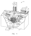
- Fig. 1 depicts an electrical discharge machining (EDM) apparatus 10.
- EDM apparatus 10 includes at least one work station 12 disposed in a tank 14, which is shown in partial cut-away to reveal work station 12 therein. Although only one work station 12 is shown in Fig. 1 for purposes of illustration, it should be noted that additional such stations, operating independently, could be disposed in tank 14. In this way, EDM apparatus 10 could machine multiple workpieces at the same time.
- tank 14 is filled with a suitable dielectric fluid, such as a dielectric oil, so that a workpiece is immersed in the fluid.
- the dielectric fluid insulates against premature spark discharge, cools the machined area, and flushes away machining debris.
- a float switch (not shown) is preferably provided in tank 14 for detecting when the dielectric fluid reaches a sufficient depth, while a filtering system (not shown) is preferably connected to tank 14 for filtering the dielectric fluid.
- EDM apparatus 10 also includes a standard EDM control system 20 which includes a power supply (or other spark generator) and a controller (e.g., a computer numerical control or CNC).
- the power supply of EDM control system 20 provides energy to work station 12 via power cables 22.
- the controller is connected to one or more linear motors 24 which, in turn, control positioning of one or more electrodes during operation of EDM apparatus 10 as discussed in greater detail herein.
- work station 12 preferably includes a first mechanism 26 for retaining a workpiece 28 in a predetermined position.
- Work station 12 also includes at least one electrode 30 for forming a feature on workpiece 28 (see Fig. 4) and a second mechanism 32 for positioning electrode 30 in a manner that is movable into and out of engagement with a designated portion of workpiece 28.
- second mechanism 32 includes a first portion 34 which is stationary and connected to first mechanism 26 so as to automatically align electrode 30 with the designated portion of workpiece 28.
- a second portion 40 of second mechanism 32 also known as a slide herein, functions to move electrode 30 relative to first portion 34 and therefore first mechanism 26.
- second mechanism 32 is configured so that electrode 30 is electrically insulated from first mechanism 26 and workpiece 28.
- an exemplary workpiece 28 depicted in Fig. 2 is a shroud for use in a gas turbine engine.
- a typical gas turbine engine employs a plurality of such shrouds arranged in an annular array around the engine's turbine rotor. The shrouds thus define an outer boundary for hot combustion gases flowing through the turbine.
- Shrouds are ordinarily made by a process in which a casting of the shroud is made and then various features are machined into the casting. It will be understood that certain features may be formed in the shroud by electrodes which are positioned above and below it, respectively, as disclosed in the prior art patents referenced herein.
- the present invention is concerned with the formation of features in the shroud at its ends, such as a seal slot. It should be noted that a shroud is only an illustrative example of one workpiece that is suitable for use with EDM apparatus 10. The present invention is not limited to such workpieces and is applicable to virtually any workpiece in which multiple features are machined.
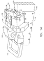
- first portion 34 of second mechanism 32 further includes a plurality of shaft members 36 retained in a shaft housing 38 in a predetermined spaced relation.
- shaft members 36 are positioned in spaced, parallel relation to each other. While a pair of shaft members 36 may be utilized, it is preferred that three shaft members 36 oriented in a substantially triangulated manner be provided.
- shaft housing 38 includes a relatively large opening 39 formed in a middle portion thereof. This opening 39 is provided in order that a portion 25 of an arm member 27 connected to linear motor 24 is able to extend therethrough and connect to slide portion 40 (see Fig. 1). In this way, linear motor is able to move electrode 30 into and out of position with respect to workpiece 28 in accordance with signals from control system 20.
- second mechanism 32 also includes a second portion 40 for retaining and positioning electrode 30.
- Second portion 40 has a locator plate 42 which includes a plurality of openings 44 formed therein (defined by a surface 46), a holder plate 48 configured for retaining electrode 30 in a predetermined location, and at least one clip member 50 for connecting holder plate 48 and locator plate 42.
- holder plate 48 may be removed from locator plate 42, and indeed work station 12, by means of a knob 49 so that electrode 30 may be repaired or replaced.
- Holder plate 48 also preferably includes a plurality of openings 52 formed therein which are positioned adjacent electrode 30 so as to permit dielectric fluid to flush the area during operation and prevent damage to electrode 30.
- bearing 54 is preferably positioned between each opening 44 in locator plate 42 and each shaft member 36.
- Bearing 54 is preferably made of an electrically insulating material, such as ceramic, any polymer material, fiberglass or other non-conductive material.
- an electrically insulating material such as ceramic, any polymer material, fiberglass or other non-conductive material.
- One particular example of such a bearing is identified as Part#RJZI-01-06, which is manufactured by Igus, Inc. of East Buffalo, Rhode Island.
- bearings 54 preferably includes a plurality of grooves 56 formed therein which permit fluid flow between each end of bearings 54. This enables the dielectric fluid and other debris to pass therethrough and not affect the ability of second portion 40 to slide along shaft members 36.
- second portion 40 of second mechanism 32 also preferably includes a base member 58 positioned adjacent and connected to holder and locator plates 48 and 42 to provide stability to second mechanism 32.
- Base member 58 likewise has a plurality of openings 60 formed therein which are sized and spaced to receive a portion of each bearing 54.
- Base member 58 also has a relatively large opening or pocket 62 formed therein which is configured to function as a manifold and supply dielectric fluid to openings 52 in holder plate 48. It will be understood that opening 62 in base member 58 is in flow communication with a dielectric fluid supply via a tube 63 connected to an opening (not shown) in base member 58.
- a cover plate 59 is preferably provided adjacent a side of base member 48 opposite electrode 30 in order to retain the fluid within opening 62.
- first mechanism 26 includes a base portion 64 for supporting workpiece 28 and a housing 66 positioned adjacent and connected to base portion 64. It will be seen that housing 66 has at least one locator member 68 associated therewith for aligning workpiece 28 in a first direction (indicated by arrow 70).
- Base portion 64 preferably further includes a first base plate 72 positioned adjacent housing 66, a second base plate 74 positioned in spaced relation to first base plate 72, and one or more spacer members 76 positioned between first and second base plates 72 and 74, where such items are connected via a plurality of bolts or dowels (not shown).
- first base plate 72 preferably includes a locator member 78 at an end adjacent to second mechanism 32 so as to align workpiece 28 in a second direction (indicated by arrow 80).
- a locator member may be associated with second base plate 72 in addition to or in place of that located on first base plate 72.
- Such locator member also may be positioned on either side of first and/or second base plates 72 and 74.
- the process of loading workpiece 28 into the predetermined position involves the initial step of placing workpiece 28 upon base portion 64 of first mechanism 26. Workpiece 28 is then slid rearwardly (in the direction of arrow 70) until it engages locator member 68 on housing 66 and laterally (in the direction of arrow 80) until it engages locator member 78 on first base plate 72. Thereafter, workpiece 28 is locked in position by means of one or more spring clips 79 which preferably are located adjacent and connected to second base plate 74 (see Fig. 1).
- First mechanism 26 preferably further includes one or more spacer members 81 located between housing 66 and a fixture mount 83 located aft of work station 12. It will be noted that spacer members 81 extend laterally beyond base portion 64 of first mechanism 26 so as to form an arm member 85. Each arm member 85 then includes an opening 87 formed therein of a predetermined size and shape.
- shaft housing 38 includes a male portion 82 and a female portion 84 which are configured to interface with arm members 85 in locking engagement. More specifically, male portion 82 is received in openings 87 of arm members 85 while a portion 89 of arm members 85 is received within female portion 84. A set screw or similar item may be utilized to maintain shaft housing 38 and arm member 85 in their connected position. In this way, mating of shaft housing 38 and arm member 85 is accomplished in a direction substantially perpendicular to the movement of second portion 40 of second mechanism 32 so as to maintain the connection and respective positioning of electrode 30 and workpiece 28 during such movement. In this embodiment, it will be noted that electrode 30 is positioned between shaft housing 38 and first mechanism 26.
- a third mechanism 86 may be located on an opposite side of first mechanism 26.
- Third mechanism 86 is preferably configured like second mechanism 32, but in mirror image, so that it causes relative movement of a second electrode (not shown) with respect to first mechanism 26.
- third mechanism 86 is preferably directly connected to first mechanism 26 in the manner described hereinabove with respect to second mechanism 32 so as to automatically align the second electrode with workpiece 28.
- third mechanism 86 is configured so that the second electrode is likewise electrically insulated from first mechanism 26 and workpiece 28.
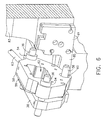
- Figs. 9-14 depict a work station 112 for an EDM apparatus 110 having an alternative configuration for positioning electrodes so as to be movable into and out of engagement with a designated portion of a workpiece 128. While much of second mechanism 132 will be similar to that described herein with respect to second mechanism 32, it will be understood that a first mechanism 126 thereof is different from first mechanism 26. Accordingly, the manner of connecting a stationary portion 134 of second mechanism 132 to first mechanism 126, as well as the device utilized to move slide portion 140 of second mechanism 132, will differ. It will also be noted that an exemplary workpiece 128 depicted is a portion of a hanger, which is utilized in a gas turbine engine to house a shroud.
- a rack and pinion device preferably receives signals from a controller (not shown) and is utilized to move slidable second portion 140 of second mechanism 132 so that electrode 130 is brought into and out of engagement with workpiece 128 at the designated portion thereof.
- shaft housing 138 is connected to first mechanism 126 by means of a base member 116 for rack and pinion system 114, as opposed to arm members 85 of spacers 81 in the previous embodiment. More specifically, a slot 139 formed on the bottom of shaft housing 138 is mated with a portion 165 of side base portion 166 so as to be retained in groove 118 of base member 116 (see Fig. 10).
- base member 116 is connected to a base portion 164 of first mechanism 126 via a connecting base portion 120.
- a handle 117 is also preferably attached to each base member 116 so as to ease handling and placement of work station 112.
- connecting base portion 120 further serves to house a first notched rod member 121 of rack and pinion system 114 which interfaces with a gear member 122 and moves generally in a vertical direction.
- a second notched rod member 123 also interfaces with gear member 122 and moves generally in a horizontal direction.
- Second notched rod member 123 includes an end portion 124 which preferably is connected to slide portion 140 of second mechanism 132 (e.g., by a shoulder screw or the like). Accordingly, electrode 130 is moved into and out of engagement with workpiece 128 as the rotary movement of gear member 122 created by first notched rod member is translated by second notched rod member 123 to slide portion 140.
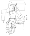
- a side portion 166 of base portion 164 preferably includes a surface 168 which functions to support slide portion 140 as it moves along shaft members 136. It will be appreciated that surface 168 is stepped from a main surface 169 of base portion 164 which is utilized to support workpiece 128.
- a locator member 172 is associated with base portion 164 so as to position workpiece 128 properly in a direction indicated by arrow 170.
- a pair of locator plates 174 and 176 are preferably positioned at each end of base portion 164 and held in place by spring clips 178 and 179, respectively, so as to position workpiece 128 properly in a lateral direction indicated by arrow 180.
- Locator plates 174 and 176 will then include openings therein so as to permit the ends of workpiece 128 to extend past main support surface 169 and be accessed by electrodes 130.
- At least one connector strip 133 is utilized to hold holder plate 148 in position against base member 158. Electrode 130 is retained in position by holder plate 148, which is in turn connected to locator plate 142. As discussed herein for second mechanism 32, locator plate 142 and base member 158 include openings therein which each include a bearing 154 made of a non-conductive material. Thus, slide portion 140 is able to move along shaft members 136 while electrode 130 is electrically insulated from first mechanism 126 (and therefore workpiece 128). At the same time, electrode 130 is automatically aligned with workpiece 128 due to the connection of shaft housing 138 with base portion 164 of first mechanism 126.
Landscapes
- Engineering & Computer Science (AREA)
- Mechanical Engineering (AREA)
- Chemical & Material Sciences (AREA)
- Chemical Kinetics & Catalysis (AREA)
- Electrochemistry (AREA)
- Physics & Mathematics (AREA)
- Thermal Sciences (AREA)
- Electrical Discharge Machining, Electrochemical Machining, And Combined Machining (AREA)
Applications Claiming Priority (2)
| Application Number | Priority Date | Filing Date | Title |
|---|---|---|---|
| US804638 | 1985-12-09 | ||
| US10/804,638 US7378611B2 (en) | 2004-03-19 | 2004-03-19 | Apparatus and method for electrical discharge machining |
Publications (3)
| Publication Number | Publication Date |
|---|---|
| EP1584395A2 true EP1584395A2 (de) | 2005-10-12 |
| EP1584395A3 EP1584395A3 (de) | 2006-12-27 |
| EP1584395B1 EP1584395B1 (de) | 2012-05-09 |
Family
ID=34912639
Family Applications (1)
| Application Number | Title | Priority Date | Filing Date |
|---|---|---|---|
| EP05251599A Expired - Lifetime EP1584395B1 (de) | 2004-03-19 | 2005-03-16 | Vorrichtung und Verfahren zum Funkenerosionsbearbeiten |
Country Status (3)
| Country | Link |
|---|---|
| US (1) | US7378611B2 (de) |
| EP (1) | EP1584395B1 (de) |
| JP (1) | JP4895517B2 (de) |
Cited By (1)
| Publication number | Priority date | Publication date | Assignee | Title |
|---|---|---|---|---|
| FR3015317A1 (fr) * | 2013-12-19 | 2015-06-26 | Snecma | Secteur d'anneau de turbine pour turbomachine d'aeronef, presentant des orifices de prehension pour machine d'usinage, et machine polyvalente d'usinage par electroerosion de secteur d'anneau |
Families Citing this family (3)
| Publication number | Priority date | Publication date | Assignee | Title |
|---|---|---|---|---|
| SG166033A1 (en) * | 2009-05-08 | 2010-11-29 | Pratt & Whitney Services Pte Ltd | Method of electrical discharge surface repair of a variable vane trunnion |
| US9700986B2 (en) | 2014-05-06 | 2017-07-11 | Pratt & Whitney Canada Corp. | Method of machining a shroud and grinding wheel therefor |
| US10307846B2 (en) * | 2015-09-15 | 2019-06-04 | General Electric Company | Electrical discharge machining system having independent electrodes, related control system and method |
Citations (4)
| Publication number | Priority date | Publication date | Assignee | Title |
|---|---|---|---|---|
| US6326576B1 (en) | 1999-09-22 | 2001-12-04 | General Electric Company | Method and apparatus for electrical discharge machining |
| US6369343B1 (en) | 2000-09-20 | 2002-04-09 | General Electric Company | Method and apparatus for electrical discharge machining |
| US6563071B2 (en) | 2001-05-15 | 2003-05-13 | General Electric Company | Method and apparatus for electrical discharge machining with multiple workstations |
| US20040050821A1 (en) | 2002-09-12 | 2004-03-18 | General Electric Company | Multi-station electrical discharge machining with single velocity command |
Family Cites Families (21)
| Publication number | Priority date | Publication date | Assignee | Title |
|---|---|---|---|---|
| US3281343A (en) * | 1963-06-10 | 1966-10-25 | Thomas J O'connor | Method of machining |
| US3454738A (en) * | 1967-03-22 | 1969-07-08 | Western Electric Co | Method of electrical discharge machining |
| US3890481A (en) * | 1969-10-10 | 1975-06-17 | Homer G Buck | Electroerosive process for manufacturing rotary dies |
| US3981786A (en) * | 1974-12-19 | 1976-09-21 | United Technologies Corporation | ECM and EDM tooling for producing holes in airfoil trailing edges |
| JPS5733923A (en) * | 1980-08-05 | 1982-02-24 | Inoue Japax Res Inc | Electric discharge machining device |
| US4544820A (en) * | 1982-09-29 | 1985-10-01 | Johnson Romain H | Die forming method and machine |
| JPS6029248A (ja) * | 1983-07-04 | 1985-02-14 | Fujitsu Ltd | 放電加工装置 |
| JPS60259319A (ja) * | 1984-06-04 | 1985-12-21 | Inoue Japax Res Inc | 放電加工装置 |
| US4792654A (en) * | 1987-11-04 | 1988-12-20 | Hughes Aircraft Company | Method and apparatus for manufacturing slow-wave structures for traveling-wave tubes |
| DE3839962C1 (de) * | 1988-11-26 | 1990-04-12 | Messerschmitt-Boelkow-Blohm Gmbh, 8012 Ottobrunn, De | |
| JPH02243223A (ja) * | 1989-03-15 | 1990-09-27 | Toshiba Corp | 放電加工用電極案内具 |
| JPH06126541A (ja) * | 1992-06-08 | 1994-05-10 | Honda Motor Co Ltd | 放電加工装置 |
| JPH068060A (ja) * | 1992-06-24 | 1994-01-18 | Honda Motor Co Ltd | 二部材の位置決め方法および装置 |
| JPH08118157A (ja) * | 1994-08-30 | 1996-05-14 | Hoden Seimitsu Kako Kenkyusho Ltd | 放電加工機 |
| JPH09108943A (ja) * | 1995-10-16 | 1997-04-28 | Toshiba Corp | 放電加工装置 |
| US5847350A (en) * | 1997-06-16 | 1998-12-08 | General Electric Company | Adjustable mount |
| DE19858159C2 (de) * | 1998-12-16 | 2003-07-10 | System 3R Internat Ab Vaelling | Kupplungsvorrichtung |
| DE19857913C2 (de) * | 1998-12-16 | 2003-10-02 | System 3R Internat Ab Vaelling | Kupplungsvorrichtung |
| US6485630B1 (en) * | 2000-08-02 | 2002-11-26 | Ford Global Technologies, Inc. | Method of reducing wear in lubricated metal cutting operation |
| US6844515B2 (en) * | 2001-10-10 | 2005-01-18 | Brett Wayne Byrnes | Method and apparatus for turbine blade machining |
| JP4032697B2 (ja) * | 2001-10-23 | 2008-01-16 | 三菱電機株式会社 | 圧縮機、圧縮機の加工方法 |
-
2004
- 2004-03-19 US US10/804,638 patent/US7378611B2/en not_active Expired - Fee Related
-
2005
- 2005-03-16 EP EP05251599A patent/EP1584395B1/de not_active Expired - Lifetime
- 2005-03-17 JP JP2005076228A patent/JP4895517B2/ja not_active Expired - Fee Related
Patent Citations (4)
| Publication number | Priority date | Publication date | Assignee | Title |
|---|---|---|---|---|
| US6326576B1 (en) | 1999-09-22 | 2001-12-04 | General Electric Company | Method and apparatus for electrical discharge machining |
| US6369343B1 (en) | 2000-09-20 | 2002-04-09 | General Electric Company | Method and apparatus for electrical discharge machining |
| US6563071B2 (en) | 2001-05-15 | 2003-05-13 | General Electric Company | Method and apparatus for electrical discharge machining with multiple workstations |
| US20040050821A1 (en) | 2002-09-12 | 2004-03-18 | General Electric Company | Multi-station electrical discharge machining with single velocity command |
Cited By (1)
| Publication number | Priority date | Publication date | Assignee | Title |
|---|---|---|---|---|
| FR3015317A1 (fr) * | 2013-12-19 | 2015-06-26 | Snecma | Secteur d'anneau de turbine pour turbomachine d'aeronef, presentant des orifices de prehension pour machine d'usinage, et machine polyvalente d'usinage par electroerosion de secteur d'anneau |
Also Published As
| Publication number | Publication date |
|---|---|
| EP1584395A3 (de) | 2006-12-27 |
| JP2005262438A (ja) | 2005-09-29 |
| EP1584395B1 (de) | 2012-05-09 |
| JP4895517B2 (ja) | 2012-03-14 |
| US20080041826A1 (en) | 2008-02-21 |
| US7378611B2 (en) | 2008-05-27 |
Similar Documents
| Publication | Publication Date | Title |
|---|---|---|
| CN108994407B (zh) | 四联导向叶片干涉气膜孔定位夹具、加工装置及加工方法 | |
| EP1314507B1 (de) | Elektrochemische Bearbeitung eines Tandemintegralrotors | |
| EP0241165A2 (de) | Apparat für Elektroentladungsbearbeitung mit wechselbarer Patrone für den Wiedervorschub der Elektrode | |
| US6941645B2 (en) | Automatic piston inserting equipment using a vision system | |
| CN104299816B (zh) | 隔离开关传动机构的装配工装 | |
| EP1584395B1 (de) | Vorrichtung und Verfahren zum Funkenerosionsbearbeiten | |
| US4670635A (en) | Multi-electrode electrical discharge machining apparatus | |
| US6326576B1 (en) | Method and apparatus for electrical discharge machining | |
| US6369343B1 (en) | Method and apparatus for electrical discharge machining | |
| EP2246139A1 (de) | Elektrodenerosive Bearbeitungsvorrichtung und Verfahren zur Bearbeitung eines Werkstücks | |
| US6563071B2 (en) | Method and apparatus for electrical discharge machining with multiple workstations | |
| EP1524059A2 (de) | Vorrichtung und Verfahren zur Bearbeitung in beengten Räumen | |
| EP1470885B1 (de) | Mehrstationenfunkenerosionsbearbeitung mit einer gemeinsamen Geschwindigkeitsregelung | |
| KR100368806B1 (ko) | 가공물 위치결정장치 | |
| EP1074328A2 (de) | Vorrichtung und Verfahren zur Bearbeitung eines Werkstückes mittels Funkenerosionbearbeitung | |
| EP1415747B1 (de) | Mehrstationen Funkenerosionsbearbeitungsmaschine mit Verminderung der Bearbeitungsunterbrechungen | |
| EP1400306A2 (de) | Verfahren und Vorrichtung zum Ausrichten einer Werkzeugmaschine | |
| CN114932279B (zh) | 一种具有等分功能的分度电磁工装及轴类零件油孔加工方法 | |
| CN222470994U (zh) | 壳体油道孔电化学去毛刺加工装置 | |
| CN217371518U (zh) | 一种节温器壳体紧凑加工夹具 | |
| US20250381607A1 (en) | Multi-station edm for vanes | |
| CN220698471U (zh) | 一种磁力快装平台 | |
| CN223748584U (zh) | 一种火花塞和喷油器隔套专用可翻转式卡盘结构 | |
| CN221435469U (zh) | 一种挖机斗杆部件组焊工装 | |
| CN217062204U (zh) | 电池负压化成设备 |
Legal Events
| Date | Code | Title | Description |
|---|---|---|---|
| PUAI | Public reference made under article 153(3) epc to a published international application that has entered the european phase |
Free format text: ORIGINAL CODE: 0009012 |
|
| AK | Designated contracting states |
Kind code of ref document: A2 Designated state(s): AT BE BG CH CY CZ DE DK EE ES FI FR GB GR HU IE IS IT LI LT LU MC NL PL PT RO SE SI SK TR |
|
| AX | Request for extension of the european patent |
Extension state: AL BA HR LV MK YU |
|
| PUAL | Search report despatched |
Free format text: ORIGINAL CODE: 0009013 |
|
| AK | Designated contracting states |
Kind code of ref document: A3 Designated state(s): AT BE BG CH CY CZ DE DK EE ES FI FR GB GR HU IE IS IT LI LT LU MC NL PL PT RO SE SI SK TR |
|
| AX | Request for extension of the european patent |
Extension state: AL BA HR LV MK YU |
|
| 17P | Request for examination filed |
Effective date: 20070627 |
|
| AKX | Designation fees paid |
Designated state(s): DE FR GB IT |
|
| 17Q | First examination report despatched |
Effective date: 20080807 |
|
| GRAP | Despatch of communication of intention to grant a patent |
Free format text: ORIGINAL CODE: EPIDOSNIGR1 |
|
| GRAS | Grant fee paid |
Free format text: ORIGINAL CODE: EPIDOSNIGR3 |
|
| GRAA | (expected) grant |
Free format text: ORIGINAL CODE: 0009210 |
|
| AK | Designated contracting states |
Kind code of ref document: B1 Designated state(s): DE FR GB IT |
|
| REG | Reference to a national code |
Ref country code: GB Ref legal event code: FG4D |
|
| REG | Reference to a national code |
Ref country code: DE Ref legal event code: R096 Ref document number: 602005034080 Country of ref document: DE Effective date: 20120712 |
|
| PLBE | No opposition filed within time limit |
Free format text: ORIGINAL CODE: 0009261 |
|
| STAA | Information on the status of an ep patent application or granted ep patent |
Free format text: STATUS: NO OPPOSITION FILED WITHIN TIME LIMIT |
|
| 26N | No opposition filed |
Effective date: 20130212 |
|
| REG | Reference to a national code |
Ref country code: DE Ref legal event code: R097 Ref document number: 602005034080 Country of ref document: DE Effective date: 20130212 |
|
| REG | Reference to a national code |
Ref country code: FR Ref legal event code: PLFP Year of fee payment: 11 |
|
| PGFP | Annual fee paid to national office [announced via postgrant information from national office to epo] |
Ref country code: DE Payment date: 20150327 Year of fee payment: 11 Ref country code: IT Payment date: 20150324 Year of fee payment: 11 |
|
| PGFP | Annual fee paid to national office [announced via postgrant information from national office to epo] |
Ref country code: FR Payment date: 20150317 Year of fee payment: 11 Ref country code: GB Payment date: 20150327 Year of fee payment: 11 |
|
| REG | Reference to a national code |
Ref country code: DE Ref legal event code: R119 Ref document number: 602005034080 Country of ref document: DE |
|
| GBPC | Gb: european patent ceased through non-payment of renewal fee |
Effective date: 20160316 |
|
| REG | Reference to a national code |
Ref country code: FR Ref legal event code: ST Effective date: 20161130 |
|
| PG25 | Lapsed in a contracting state [announced via postgrant information from national office to epo] |
Ref country code: FR Free format text: LAPSE BECAUSE OF NON-PAYMENT OF DUE FEES Effective date: 20160331 Ref country code: GB Free format text: LAPSE BECAUSE OF NON-PAYMENT OF DUE FEES Effective date: 20160316 Ref country code: DE Free format text: LAPSE BECAUSE OF NON-PAYMENT OF DUE FEES Effective date: 20161001 |
|
| PG25 | Lapsed in a contracting state [announced via postgrant information from national office to epo] |
Ref country code: IT Free format text: LAPSE BECAUSE OF NON-PAYMENT OF DUE FEES Effective date: 20160316 |