EP1584505B1 - Klappenantrieb, insbesondere für Luftklappen - Google Patents
Klappenantrieb, insbesondere für Luftklappen Download PDFInfo
- Publication number
- EP1584505B1 EP1584505B1 EP05005790A EP05005790A EP1584505B1 EP 1584505 B1 EP1584505 B1 EP 1584505B1 EP 05005790 A EP05005790 A EP 05005790A EP 05005790 A EP05005790 A EP 05005790A EP 1584505 B1 EP1584505 B1 EP 1584505B1
- Authority
- EP
- European Patent Office
- Prior art keywords
- servomotor
- slot
- damper
- heater
- ventilator
- Prior art date
- Legal status (The legal status is an assumption and is not a legal conclusion. Google has not performed a legal analysis and makes no representation as to the accuracy of the status listed.)
- Expired - Lifetime
Links
Images

Classifications
-
- B—PERFORMING OPERATIONS; TRANSPORTING
- B60—VEHICLES IN GENERAL
- B60H—ARRANGEMENTS OF HEATING, COOLING, VENTILATING OR OTHER AIR-TREATING DEVICES SPECIALLY ADAPTED FOR PASSENGER OR GOODS SPACES OF VEHICLES
- B60H1/00—Heating, cooling or ventilating devices
- B60H1/00642—Control systems or circuits; Control members or indication devices for heating, cooling or ventilating devices
- B60H1/00664—Construction or arrangement of damper doors
- B60H1/00671—Damper doors moved by rotation; Grilles
-
- B—PERFORMING OPERATIONS; TRANSPORTING
- B60—VEHICLES IN GENERAL
- B60H—ARRANGEMENTS OF HEATING, COOLING, VENTILATING OR OTHER AIR-TREATING DEVICES SPECIALLY ADAPTED FOR PASSENGER OR GOODS SPACES OF VEHICLES
- B60H1/00—Heating, cooling or ventilating devices
- B60H1/00642—Control systems or circuits; Control members or indication devices for heating, cooling or ventilating devices
- B60H1/00664—Construction or arrangement of damper doors
Definitions
- the invention relates to a damper drive, in particular for louvers of a ventilation, heating and / or air conditioning device, in particular for a motor vehicle, according to the preamble of claim 1 and a ventilation, heating and / or air conditioning device with a damper drive according to claim 9.
- flaps for controlling an air flow for example for controlling a coming from a motor vehicle air conditioner, the vehicle interior to be supplied air flow, operated by DC servomotors.
- DC servomotors At such a servomotor is constantly a constant voltage, even if the flap has reached its end position.
- actuators used for damper actuators are known in which switched off in the end position by means of an electronic device, the servomotor or the voltage is reduced.
- this requires additional electronic components in the HMI device, such as e.g. a timer, a PTC protection circuit, a protective resistor, which leads to a loss of voltage at the actuator.
- From the DE 11 47 303 B is a zero-voltage restoring device for an electric motor drive of actuators known.
- Servo motors are known for other uses, which have an internal derailleur, so that they turn themselves off after a certain adjustment.
- a not energized in its end position DC servo motor is provided, wherein no electronic circuit is provided.
- the function of the conventional electronic circuits assumes a suitably designed kinematics and a servomotor with an internal derailleur, so that the servomotor is turned off in at least one of its end positions, so that no unnecessary voltage loss occurs on the servomotor. Furthermore, such a configuration increases the possible service life, in particular with regard to the number of running cycles.
- the design of the kinematics allows the same servomotor to be used for different series or areas of use, in particular with the same adjustment path, and only the kinematics have to be changed slightly. As a result, the cost of the servomotor can be reduced as a result of the larger number and also simplify storage.
- the kinematics on a slot-pin guide Preferably, the kinematics on a slot-pin guide.
- the term slot is to be interpreted very broadly. In particular, it does not necessarily have to have a constant width.
- the slot preferably has no constant width and is designed such that it has a linear region, as it passes through an adjustment of the flap.
- the linear region is preferably formed in the longitudinal direction of a lever arm, in which the slot is provided.
- the kinematics preferably has a slot-pin guide with a slot which is formed such that it has at least one, preferably two, in a curve, in particular in a circular arc, extending portions.
- a slot-pin guide with a slot which is formed such that it has at least one, preferably two, in a curve, in particular in a circular arc, extending portions.
- two are provided in a region extending in a circular arc areas, said in a circular arc extending areas are preferably separated by a linear region.
- the linear region preferably forms the mirror axis of the regions extending in a radius, wherein the two regions extending in a circular arc may have different lengths on the side spaced from the linear region.
- a bias is preferably exerted on the flap in at least one of its end positions, so that a good fit of the flap is ensured in a simple and cost-effective manner.
- Manufacturing tolerances and / or switching point tolerances can be particularly easily absorbed by the design of the slot of the slot-pin guide.
- the damper drive according to the invention is used in a ventilation, heating and / or air conditioning device comprising at least one of the following components: heat exchanger, radiator, evaporator, filter, temperature mixing valve, mixing chamber, one or more flow channels and one or more control valves for distributing the air to the outlet channels
- a damper drive 1 has a servomotor M with an internal derailleur, which engages via a motor lever arm 2 with a provided at the end of the same pin 3 in a provided in a flap lever arm 4 slot 5 with a contour closer to the later will be received.
- the flap lever arm 4 is part of a flap K, which is pivotable about a pivot axis S.
- the flap K is used to control an air flow in an automotive air conditioning system (not shown).
- the flap K is pivotable according to the first embodiment by an angle of 55 ° between two end positions.
- the Swing angle of the servomotor M 90 °.
- the slot 5 has a contour consisting of a linear first region 6, the extension of which passes through the pivot axis S, two extending in a circular arc second regions 7, wherein the Radius of the circular arcs of the two areas corresponds to the distance between the pivot axis of the motor M and the pin 3, and a connecting portion 7 ', wherein the transitions between the individual regions 6, 7 and 7' are rounded.
- the second regions 7 are slightly longer than necessary.
- the two second regions 7 are arranged at an angle not equal to 90 ° to the linear first region 6, wherein the longitudinal axis of the linear first region 6 forms the mirror axis of the second regions 7. In this case, the second regions 7 are formed differently long.
- the flap K is in its other end position, which in Fig. 1 is indicated by a dash-dot line. In this case, a tight contact of the flap K is ensured at its contact surface due to a certain bias.
- Another panning of the motor lever arm 2 has no influence on the flap position. Rather, the pin 3 slides along the second of the second regions 7 "until about the end of the same the motor M automatically shuts off due to the predetermined pivot angle of 90 °.
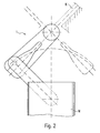
- Fig. 2 is a second embodiment of a damper actuator 1 is shown, which substantially coincides with the first embodiment, however, the pivot angle of the flap K in this case is 90 ° and thus corresponds exactly to the tilt angle of the servomotor M.
- At least one of the second areas is not exactly in the arc passed through the pin, but is slightly inclined aligned thereto, whereby a slow build-up of a certain bias to ensure airtight installation of the flap can be ensured at its contact surface.
Landscapes
- Physics & Mathematics (AREA)
- Thermal Sciences (AREA)
- Engineering & Computer Science (AREA)
- Mechanical Engineering (AREA)
- Air-Conditioning For Vehicles (AREA)
- Fluid-Damping Devices (AREA)
- Air-Flow Control Members (AREA)
- Electrically Driven Valve-Operating Means (AREA)
Description
- Die Erfindung betrifft einen Klappenantrieb, insbesondere für Luftklappen einer Belüftungs-, Heizungs- und/oder Klimatisierungseinrichtung insbesondere für ein Kraftfahrzeug, gemäß dem Oberbegriff des Anspruchs 1 und eine Belüftungs-, Heizungs- und/oder Klimatisierungseinrichtung mit einem Klappenantrieb gemäß Anspruch 9.
- Üblicherweise werden Klappen zur Steuerung eines Luftstroms, beispielsweise zur Steuerung eines von einer Kraftfahrzeug-Klimaanlage kommenden, dem Fahrzeuginnenraum zuzuführenden Luftstroms, mittels Gleichstrom-Stellmotoren betätigt. An einem derartigen Stellmotor liegt beständig eine konstante Spannung an, auch wenn die Klappe ihre Endstellung erreicht hat.
- Ferner sind für Klappenantriebe verwendete Stellmotoren bekannt, bei denen in der Endstellung mit Hilfe einer elektronischen Vorrichtung der Stellmotor abgeschaltet oder die Spannung reduziert wird. Hierfür sind jedoch zusätzliche elektronische Bauteile im Bediengerät erforderlich, wie z.B. eine Zeitschaltung, eine PTC-Schutzschaltung, ein Schutzwiderstand, welcher zu einem Spannungsverlust am Stellmotor führt.
- Aus der
DE 11 47 303 B ist eine Nullspannungs-Rückstelleinrichtung für einen elektromotorischen Antrieb von Stellgliedern bekannt. - Derartige Klappenantriebe lassen somit noch Wünsche offen.
- Für andere Verwendungszwecke sind Stellmotoren bekannt, die ein internes Schaltwerk aufweisen, so dass sie sich nach einem bestimmten Verstellweg selbst abschalten.
- Des Weiteren ist aus der
DE 44 20160 eine Übertragungsvorrichtung zur Steuerung zweier Klappen mit Hilfe von Nochen bekannt. - Es ist Aufgabe der Erfindung, einen verbesserten und kostengünstigen Klappenantrieb zur Verfügung zu stellen.
- Diese Aufgabe wird gelöst durch einen Klappenantrieb mit den Merkmalen des Anspruchs 1. Vorteilhafte Ausgestaltungen sind Gegenstand der Unteransprüche.
- Erfindungsgemäß ist für einen Klappenantrieb, insbesondere für Luftklappen eines Kraftfahrzeugbelüftungs- und/oder -klimatisierungssystems, ein in seiner Endstellung nicht bestromter Gleichstrom-Stellmotor vorgesehen, wobei keine Elektronik-Schaltung vorgesehen ist. Die Funktion der herkömmlichen Elektronik-Schaltungen übernimmt eine entsprechend ausgebildete Kinematik und ein Stellmotor mit einem internen Schaltwerk, so dass der Stellmotor in mindestens einer seiner Endstellungen ausgeschaltet ist, so dass kein unnötiger Spannungsverlust am Stellmotor erfolgt. Ferner wird durch eine derartige Ausgestaltung die mögliche Lebensdauer, insbesondere in Hinblick auf die Anzahl der Laufzyklen, erhöht.
- Die Ausgestaltung der Kinematik ermöglicht unter anderem, dass für unterschiedliche Serien oder Einsatzbereiche der gleiche Stellmotor verwendet werden kann, insbesondere mit gleichem Verstellweg, und lediglich die Kinematik leicht verändert werden muss. Dadurch lassen sich die Kosten für den Stellmotor in Folge der größeren Stückzahl verringern und zudem die Lagerhaltung vereinfachen.
- Bevorzugt weist die Kinematik eine Schlitz-Zapfen-Führung auf. Dabei ist der Begriff Schlitz sehr weit auszulegen. Insbesondere muss er nicht notwendigerweise eine konstante Breite aufweisen. Vorliegend weist der Schlitz bevorzugt keine konstante Breite auf und ist derart ausgebildet, dass er einen linearen Bereich aufweist, bei Durchlaufen dessen eine Verstellung der Klappe erfolgt. Der lineare Bereich ist hierbei bevorzugt in Längsrichtung eines Hebelarms ausgebildet, in dem der Schlitz vorgesehen ist.
- Die Kinematik weist vorzugsweise eine Schlitz-Zapfen-Führung mit einem Schlitz auf, der derart ausgebildet ist, dass er mindestens einen, vorzugsweise zwei, in einer Kurve, insbesondere in einem Kreisbogen, verlaufende Bereiche aufweist. Hierbei erfolgt bevorzugt bei Durchlaufen des kurvenförmigen Bereichs keine oder nur eine unwesentliche Verstellung der Klappe zum Aufbau einer Vorspannung, so dass die Klappe dicht an ihrer Anlage anliegt. Bevorzugt sind zwei in einen in einem Kreisbogen verlaufende Bereiche vorgesehen, wobei diese in einem Kreisbogen verlaufende Bereiche bevorzugt getrennt durch einen linearen Bereich sind. Der lineare Bereich bildet vorzugsweise die Spiegelachse der in einem Radius verlaufende Bereiche, wobei die beiden in einem Kreisbogen verlaufenden Bereiche auf der von dem linearen Bereich beabstandeten Seite unterschiedlich lang ausgebildet sein können.
- Auf die Klappe wird in Folge der vorhandenen Kinematik vorzugsweise in zumindest einer ihrer Endstellungen eine Vorspannung ausgeübt, so dass auf einfache und kostengünstige Weise eine gute Anlage der Klappe gewährleistet ist.
- Fertigungstoleranzen und/oder Schaltpunkttoleranzen können besonders einfach durch die Ausgestaltung des Schlitzes der Schlitz-Zapfen-Führung aufgefangen werden.
- Gemäß einer bevorzugten Weiterbildung wird der erfindungsgemäße Klappenantrieb in einer Belüftungs-, Heizungs- und/oder Klimatisierungseinrichtung eingesetzt, die zumindest eines der folgenden Bauteile umfasst: Wärmetauscher, Heizkörper, Verdampfer, Filter, Temperaturmischklappe, Mischkammer, einen oder mehrere Strömungskanäle und eine oder mehrere Steuerklappen zur Verteilung der Luft auf die Austrittskanäle
- Im Folgenden wird die Erfindung anhand zweier Ausführungsbeispiele unter Bezugnahme auf die Zeichnung im Einzelnen erläutert. In der Zeichnung zeigen:
- Fig. 1
- einen Schnitt quer durch einen Klappenantrieb gemäß dem ersten Ausführungsbeispiel, wobei die Klappe in einer ihrer Endstellungen dargestellt ist und die andere Endstellung durch eine Strich-Punkt-Linie angedeutet ist, und
- Fig. 2
- einen Schnitt quer durch einen Klappenantrieb gemäß dem zweiten Ausführungsbeispiel, wobei die Klappe in einer ihrer Endstellungen dargestellt ist und die andere Endstellung durch eine Strich-Punkt-Linie angedeutet ist.
- Ein Klappenantrieb 1 weist einen Stellmotor M mit einem internen Schaltwerk auf, welcher über einen Motor-Hebelarm 2 mit einem am Ende desselben vorgesehenen Zapfen 3 in einen in einem Klappen-Hebelarm 4 vorgesehen Schlitz 5 mit einer Kontur eingreift, auf die an späterer Stelle näher eingegangen wird. Der Klappen-Hebelarm 4 ist Teil einer Klappe K, die um eine Schwenkachse S verschwenkbar ist. Die Klappe K dient der Steuerung eines Luftstroms in einer Kraftfahrzeug-Klimaanlage (nicht dargestellt).
- Die Klappe K ist gemäß dem ersten Ausführungsbeispiel um einen Winkel von 55° zwischen zwei Endstellungen verschwenkbar. Dagegen beträgt der Schwenkwinkel des Stellmotors M 90°. Um den gewünschten Winkel von 55° auf den vorgegebenen Schwenkwinkel des Stellmotors M abzustimmen weist der Schlitz 5 eine Kontur auf, bestehend aus einem linearen ersten Bereich 6, dessen Verlängerung durch die Schwenkachse S verläuft, zwei in einem Kreisbogen verlaufende zweite Bereiche 7, wobei der Radius der Kreisbögen der beiden Bereiche dem Abstand zwischen der Schwenkachse des Motors M und dem Zapfen 3 entspricht, und einem Verbindungsbereich 7', wobei die Übergänge zwischen den einzelnen Bereichen 6, 7 und 7' abgerundet ausgebildet sind. Aus Toleranzgründen sind die zweiten Bereiche 7 etwas länger ausgebildet als erforderlich. Die beiden zweiten Bereiche 7 sind in einem Winkel ungleich 90° zum linearen ersten Bereich 6 angeordnet, wobei die Längsachse des linearen ersten Bereichs 6 die Spiegelachse der zweiten Bereiche 7 bildet. Dabei sind die zweiten Bereiche 7 unterschiedlich lang ausgebildet.
- Bezug nehmend auf
Fig. 1 wird im Folgenden die Kinematik des Klappenantriebs 1 näher erläutert. Erfolgt eine Betätigung des Stellmotors M, so schwenkt der Motor-Hebelarm 2 entgegen dem Uhrzeigersinn und der Zapfen 3 gleitet entlang dem ersten der zweiten Bereiche 7'. Anschließend gelangt er zum linearen ersten Bereich 6. Da der Zapfen 3 dadurch in Anlage an die inFig. 1 links dargestellte Seite des linearen ersten Bereichs 6 gelangt, schwenkt der Klappen-Hebelarm 4 und somit die Klappe K im Uhrzeigersinn. Auf Grund des weiteren Schwenkens des Motor-Hebelarms 2 gelangt der Zapfen 3 weiter in den linearen ersten Bereich 6 bis er in der Stellung, in der die beiden Hebelarme 2 und 4 parallel zueinander angeordnet sind, den Endpunkt erreicht und bei weiterem Schwenken des Motor-Hebelarms 2 sich wieder nach außen bewegt. Erreicht der Zapfen 3 das Ende des linearen ersten Bereichs 6, so befindet sich auch die Klappe K in ihrer anderen Endstellung, die inFig. 1 durch eine Strich-Punkt-Linie angedeutet ist. Hierbei ist auf Grund einer gewissen Vorspannung eine dichte Anlage der Klappe K an ihrer Anlagefläche gewährleistet. Ein weiteres Schwenken des Motor-Hebelarms 2 hat keinen Einfluss mehr auf die Klappenstellung. Vielmehr gleitet der Zapfen 3 entlang dem zweiten der zweiten Bereiche 7" bis etwa am Ende desselben der Stellmotor M auf Grund des vorgegebenen Schwenkwinkels von 90° automatisch abschaltet. Die Rückbewegung erfolgt entsprechend. - In
Fig. 2 ist ein zweites Ausführungsbeispiel eines Klappenantriebs 1 dargestellt, das im Wesentlichen mit dem ersten Ausführungsbeispiel übereinstimmt, jedoch beträgt der Schwenkwinkel der Klappe K in diesem Fall 90° und entspricht somit genau dem Schwenkwinkel des Stellmotors M. - Gemäß einer nicht in der Zeichnung dargestellten Variante verläuft mindestens einer der zweiten Bereiche nicht exakt im vom Zapfen durchlaufenen Kreisbogen, sondern ist leicht geneigt hierzu ausgerichtet, wodurch ein langsames Aufbauen einer gewissen Vorspannung zur Sicherstellung einer luftdichten Anlage der Klappe an ihrer Anlagefläche sichergestellt werden kann.
-
- 1
- Klappenantrieb
- 2
- Motor-Hebelarm
- 3
- Zapfen
- 4
- Klappen-Hebelarm
- 5
- Schlitz
- 6
- lineare, erster Bereich
- 7
- zweiter Bereich
- 7'
- erster zweiter Bereich
- 7"
- zweiter zweiter Bereich
- K
- Klappe
- M
- Stellmotor
- S
- Schwenkachse
Claims (10)
- Klappenantrieb, insbesondere für Luftklappen einer Belüftungs-, Heizungs- und/oder Klimatisierungseinrichtung eines Kraftfahrzeugs, welche einen Stellmotor (M) mit einem festen Verstellweg und mindestens eine Klappe (K) umfasst, wobei der Stellmotor (M) ein internes Schaltwerk aufweist und die Kinematik der Klappe (K) dem Verstellweg des Stellmotors (M) entspricht, dadurch gekennzeichnet, dass der Stellmotor in mindestens einer Endstellung automatisch abschaltbar ist und auf die Klappe (K) in der zumindest einen Endstellung eine Vorspannung ausgeübt wird.
- Klappenantrieb nach Anspruch 1, dadurch gekennzeichnet, dass die Kinematik eine Schlitz-Zapfen-Führung aufweist, wobei der Schlitz derart ausgebildet ist, dass er einen linearen Bereich (6) aufweist, bei Durchlaufen dessen eine Verstellung der Klappe (K) erfolgt.
- Klappenantrieb nach Anspruch 1 oder 2, dadurch gekennzeichnet, dass die Kinematik eine Schlitz-Zapfen-Führung aufweist, wobei der Schlitz derart ausgebildet ist, dass er mindestens einen in einem Kreisbogen verlaufenden Bereich (7) aufweist, bei Durchlaufen dessen keine Verstellung der Klappe (K) erfolgt.
- Klappenantrieb nach Anspruch 3; dadurch gekennzeichnet, dass zwei in einen in einem Kreisbogen verlaufende Bereiche (7', 7") vorgesehen sind.
- Klappenantrieb nach Anspruch 4, dadurch gekennzeichnet, dass die in einem Kreisbogen verlaufende Bereiche (7', 7") durch einen linearen Bereich (6) getrennt sind.
- Klappenantrieb nach Anspruch 5, dadurch gekennzeichnet, dass der lineare Bereich (6) entlang der Spiegelachse der in einem Radius verlaufenden Bereiche (7', 7") verläuft, wobei die beiden in einem Kreisbogen verlaufenden Bereiche (7', 7") auf der von dem linearen Bereich (6) beabstandeten Seite unterschiedlich lang ausgebildet sein können.
- Klappenantrieb nach einem der vorhergehenden Ansprüche, dadurch gekennzeichnet, dass Fertigungstoleranzen und/oder Schaltpunkttoleranzen in der Ausgestaltung des Schlitzes der Schlitz-Zapfen-Führung aufgefangen sind.
- Verwendung eines Stellmotors (M) mit internem Schaltwerk als Klappenantrieb (1) nach einem der vorhergehenden Ansprüche, insbesondere für Luftklappen einer Belüftungs-, Heizungs- und/oder Klimatisierungseinrichtung, wobei die Kinematik der Klappe (K) dem Verstellweg des Stellmotors (M) entspricht.
- Belüftungs-, Heizungs- und/oder Klimatisierungseinrichtung, dadurch gekennzeichnet, dass die Belüftungs-, Heizungs- und/oder Klimatisierungseinrichtung einen Klappenantrieb nach einem der Ansprüche 1 bis 7 aufweist.
- Belüftungs-, Heizungs- und/oder Klimatisierungseinrichtung, nach Anspruch 9, dadurch gekennzeichnet, dass die Belüftungs-, Heizungs- und/oder Klimatisierungseinrichtung zumindest eines der folgenden Bauteile umfasst: Wärmetauscher, Heizkörper, Verdampfer, Filter, Temperaturmischklappe, Mischkammer, einen oder mehrere Strömungskanäle und eine oder mehrere Steuerklappen zur Verteilung der Luft auf die Austrittskanäle.
Applications Claiming Priority (2)
| Application Number | Priority Date | Filing Date | Title |
|---|---|---|---|
| DE102004017617 | 2004-04-07 | ||
| DE102004017617A DE102004017617A1 (de) | 2004-04-07 | 2004-04-07 | Klappenantrieb, insbesondere für Luftklappen |
Publications (2)
| Publication Number | Publication Date |
|---|---|
| EP1584505A1 EP1584505A1 (de) | 2005-10-12 |
| EP1584505B1 true EP1584505B1 (de) | 2008-11-05 |
Family
ID=34895553
Family Applications (1)
| Application Number | Title | Priority Date | Filing Date |
|---|---|---|---|
| EP05005790A Expired - Lifetime EP1584505B1 (de) | 2004-04-07 | 2005-03-17 | Klappenantrieb, insbesondere für Luftklappen |
Country Status (3)
| Country | Link |
|---|---|
| EP (1) | EP1584505B1 (de) |
| AT (1) | ATE413295T1 (de) |
| DE (2) | DE102004017617A1 (de) |
Families Citing this family (1)
| Publication number | Priority date | Publication date | Assignee | Title |
|---|---|---|---|---|
| EP4438435A1 (de) * | 2023-03-28 | 2024-10-02 | Knorr-Bremse España S.A. | Luftklappe |
Family Cites Families (8)
| Publication number | Priority date | Publication date | Assignee | Title |
|---|---|---|---|---|
| DE1147303B (de) * | 1961-07-18 | 1963-04-18 | Landis & Gyr Ag | Nullspannungs-Rueckstelleinrichtung fuer einen elektromotorischen Antrieb von Stellgliedern |
| DE3143672A1 (de) * | 1981-11-04 | 1983-05-11 | Daimler-Benz Ag, 7000 Stuttgart | "vorrichtung zum betaetigen einer klappe" |
| DE3603851A1 (de) * | 1986-02-07 | 1987-08-13 | Meyer Fa Rud Otto | Luftklappe mit stellantrieb |
| DE4231639C1 (de) * | 1992-09-22 | 1994-05-26 | Daimler Benz Ag | Betätigungsvorrichtung für ein in zwei Endlagen umschaltbares Stellglied, insbesondere für Luftklappen |
| FR2706818B1 (de) * | 1993-06-25 | 1995-08-04 | Valeo Thermique Habitacle | |
| JPH10278548A (ja) * | 1997-04-10 | 1998-10-20 | Zexel Corp | 制御レバー装置 |
| JP2000038021A (ja) * | 1998-07-21 | 2000-02-08 | Denso Corp | 車両用空調装置及び流量制御機構 |
| JP4433615B2 (ja) * | 2001-01-18 | 2010-03-17 | 株式会社デンソー | リンク機構 |
-
2004
- 2004-04-07 DE DE102004017617A patent/DE102004017617A1/de not_active Withdrawn
-
2005
- 2005-03-17 AT AT05005790T patent/ATE413295T1/de not_active IP Right Cessation
- 2005-03-17 DE DE502005005846T patent/DE502005005846D1/de not_active Expired - Lifetime
- 2005-03-17 EP EP05005790A patent/EP1584505B1/de not_active Expired - Lifetime
Also Published As
| Publication number | Publication date |
|---|---|
| DE102004017617A1 (de) | 2005-10-27 |
| EP1584505A1 (de) | 2005-10-12 |
| DE502005005846D1 (de) | 2008-12-18 |
| ATE413295T1 (de) | 2008-11-15 |
Similar Documents
| Publication | Publication Date | Title |
|---|---|---|
| EP1207062B1 (de) | Luftaustritt für Belüftungsanlagen | |
| EP4210984B1 (de) | Luftführungssteuerung | |
| DE102019120516A1 (de) | Luftausströmer | |
| DE102015110481A1 (de) | Vorrichtung zum Beheizen, Belüften und/oder Klimatisieren eines Fahrzeuginnenraums | |
| EP0354163B1 (de) | Vorrichtung zum Beheizen des Fahrgastraumes eines Kraftfahrzeuges | |
| EP1752324B1 (de) | Luftdüse | |
| DE10152221B4 (de) | Heizungs- oder Klimaanlage für ein Fahrzeug | |
| EP1719645A1 (de) | Stellvorrichtung für wenigstens drei Klappen einer Belüftungs-, Heizungs-oder Klimaanlage eines Kraftfahrzeugs | |
| DE3226438C2 (de) | Steuervorrichtung für die Luftströmung in Heiz- und/oder Klimaanlagen von Kraftfahrzeugen | |
| DE10256619B3 (de) | Klimagerät für Fahrzeuge | |
| EP2174809B1 (de) | Fahrzeugklimaanlage | |
| EP0841202B1 (de) | Heiz- oder Klimaanlage | |
| DE102011077639A1 (de) | Kraftfahrzeugklimaanlage | |
| EP1522434B1 (de) | Klimaanlage, insbesondere Kraftfahrzeug-Klimaanlage | |
| EP1584505A1 (de) | Klappenantrieb, insbesondere für Luftklappen | |
| EP1407903B1 (de) | Heizungs- oder Klimaanlage für ein Kraftfahrzeug mit einer Vorrichtung zur Regelung der Luftzufuhr | |
| DE4024513A1 (de) | Vorrichtung zum verstellen einer schwenkbaren luftduese | |
| DE2403316C3 (de) | Steuervorrichtung für Klimaanlagen in Fahrzeugen, insbesondere Kraftfahrzeugen | |
| DE8710950U1 (de) | Vorrichtung zur Steuerung und Lenkung der aus einer Heizungs-, Belüftungs- und/oder Klimaanlage austretenden Luft | |
| EP1792760A1 (de) | Klimaanlage, insbesondere für ein Kraftfahrzeug | |
| EP1689601B1 (de) | Klappe, insbesondere für ein luftführungsgehäuse einer kraftfahrzeug-klimaanlage | |
| EP4159499B1 (de) | Luftausströmer für ein fahrzeug | |
| DE69703722T2 (de) | Lüftungsanlage für Passagierfahrzeug, insbesondere Omnibus | |
| EP1738941A1 (de) | Kraftfahrzeug-Klimaanlage | |
| EP1555148B1 (de) | Klimatisierungsvorrichtung, insbesondere für ein Kraftfahrzeug |
Legal Events
| Date | Code | Title | Description |
|---|---|---|---|
| PUAI | Public reference made under article 153(3) epc to a published international application that has entered the european phase |
Free format text: ORIGINAL CODE: 0009012 |
|
| AK | Designated contracting states |
Kind code of ref document: A1 Designated state(s): AT BE BG CH CY CZ DE DK EE ES FI FR GB GR HU IE IS IT LI LT LU MC NL PL PT RO SE SI SK TR |
|
| AX | Request for extension of the european patent |
Extension state: AL BA HR LV MK YU |
|
| 17P | Request for examination filed |
Effective date: 20060412 |
|
| AKX | Designation fees paid |
Designated state(s): AT BE BG CH CY CZ DE DK EE ES FI FR GB GR HU IE IS IT LI LT LU MC NL PL PT RO SE SI SK TR |
|
| GRAP | Despatch of communication of intention to grant a patent |
Free format text: ORIGINAL CODE: EPIDOSNIGR1 |
|
| GRAS | Grant fee paid |
Free format text: ORIGINAL CODE: EPIDOSNIGR3 |
|
| GRAA | (expected) grant |
Free format text: ORIGINAL CODE: 0009210 |
|
| AK | Designated contracting states |
Kind code of ref document: B1 Designated state(s): AT BE BG CH CY CZ DE DK EE ES FI FR GB GR HU IE IS IT LI LT LU MC NL PL PT RO SE SI SK TR |
|
| REG | Reference to a national code |
Ref country code: GB Ref legal event code: FG4D Free format text: NOT ENGLISH |
|
| REG | Reference to a national code |
Ref country code: CH Ref legal event code: EP |
|
| REG | Reference to a national code |
Ref country code: IE Ref legal event code: FG4D Free format text: LANGUAGE OF EP DOCUMENT: GERMAN |
|
| REF | Corresponds to: |
Ref document number: 502005005846 Country of ref document: DE Date of ref document: 20081218 Kind code of ref document: P |
|
| NLV1 | Nl: lapsed or annulled due to failure to fulfill the requirements of art. 29p and 29m of the patents act | ||
| LTIE | Lt: invalidation of european patent or patent extension |
Effective date: 20081105 |
|
| PG25 | Lapsed in a contracting state [announced via postgrant information from national office to epo] |
Ref country code: LT Free format text: LAPSE BECAUSE OF FAILURE TO SUBMIT A TRANSLATION OF THE DESCRIPTION OR TO PAY THE FEE WITHIN THE PRESCRIBED TIME-LIMIT Effective date: 20081105 Ref country code: ES Free format text: LAPSE BECAUSE OF FAILURE TO SUBMIT A TRANSLATION OF THE DESCRIPTION OR TO PAY THE FEE WITHIN THE PRESCRIBED TIME-LIMIT Effective date: 20090216 |
|
| PG25 | Lapsed in a contracting state [announced via postgrant information from national office to epo] |
Ref country code: FI Free format text: LAPSE BECAUSE OF FAILURE TO SUBMIT A TRANSLATION OF THE DESCRIPTION OR TO PAY THE FEE WITHIN THE PRESCRIBED TIME-LIMIT Effective date: 20081105 Ref country code: SI Free format text: LAPSE BECAUSE OF FAILURE TO SUBMIT A TRANSLATION OF THE DESCRIPTION OR TO PAY THE FEE WITHIN THE PRESCRIBED TIME-LIMIT Effective date: 20081105 Ref country code: IS Free format text: LAPSE BECAUSE OF FAILURE TO SUBMIT A TRANSLATION OF THE DESCRIPTION OR TO PAY THE FEE WITHIN THE PRESCRIBED TIME-LIMIT Effective date: 20090305 Ref country code: NL Free format text: LAPSE BECAUSE OF FAILURE TO SUBMIT A TRANSLATION OF THE DESCRIPTION OR TO PAY THE FEE WITHIN THE PRESCRIBED TIME-LIMIT Effective date: 20081105 Ref country code: PL Free format text: LAPSE BECAUSE OF FAILURE TO SUBMIT A TRANSLATION OF THE DESCRIPTION OR TO PAY THE FEE WITHIN THE PRESCRIBED TIME-LIMIT Effective date: 20081105 |
|
| REG | Reference to a national code |
Ref country code: IE Ref legal event code: FD4D |
|
| PG25 | Lapsed in a contracting state [announced via postgrant information from national office to epo] |
Ref country code: BG Free format text: LAPSE BECAUSE OF FAILURE TO SUBMIT A TRANSLATION OF THE DESCRIPTION OR TO PAY THE FEE WITHIN THE PRESCRIBED TIME-LIMIT Effective date: 20090205 Ref country code: IE Free format text: LAPSE BECAUSE OF FAILURE TO SUBMIT A TRANSLATION OF THE DESCRIPTION OR TO PAY THE FEE WITHIN THE PRESCRIBED TIME-LIMIT Effective date: 20081105 Ref country code: DK Free format text: LAPSE BECAUSE OF FAILURE TO SUBMIT A TRANSLATION OF THE DESCRIPTION OR TO PAY THE FEE WITHIN THE PRESCRIBED TIME-LIMIT Effective date: 20081105 Ref country code: EE Free format text: LAPSE BECAUSE OF FAILURE TO SUBMIT A TRANSLATION OF THE DESCRIPTION OR TO PAY THE FEE WITHIN THE PRESCRIBED TIME-LIMIT Effective date: 20081105 Ref country code: RO Free format text: LAPSE BECAUSE OF FAILURE TO SUBMIT A TRANSLATION OF THE DESCRIPTION OR TO PAY THE FEE WITHIN THE PRESCRIBED TIME-LIMIT Effective date: 20081105 |
|
| PG25 | Lapsed in a contracting state [announced via postgrant information from national office to epo] |
Ref country code: PT Free format text: LAPSE BECAUSE OF FAILURE TO SUBMIT A TRANSLATION OF THE DESCRIPTION OR TO PAY THE FEE WITHIN THE PRESCRIBED TIME-LIMIT Effective date: 20090406 Ref country code: SE Free format text: LAPSE BECAUSE OF FAILURE TO SUBMIT A TRANSLATION OF THE DESCRIPTION OR TO PAY THE FEE WITHIN THE PRESCRIBED TIME-LIMIT Effective date: 20090205 Ref country code: CZ Free format text: LAPSE BECAUSE OF FAILURE TO SUBMIT A TRANSLATION OF THE DESCRIPTION OR TO PAY THE FEE WITHIN THE PRESCRIBED TIME-LIMIT Effective date: 20081105 |
|
| PLBE | No opposition filed within time limit |
Free format text: ORIGINAL CODE: 0009261 |
|
| STAA | Information on the status of an ep patent application or granted ep patent |
Free format text: STATUS: NO OPPOSITION FILED WITHIN TIME LIMIT |
|
| BERE | Be: lapsed |
Owner name: BEHR G.M.B.H. & CO. KG Effective date: 20090331 |
|
| PG25 | Lapsed in a contracting state [announced via postgrant information from national office to epo] |
Ref country code: SK Free format text: LAPSE BECAUSE OF FAILURE TO SUBMIT A TRANSLATION OF THE DESCRIPTION OR TO PAY THE FEE WITHIN THE PRESCRIBED TIME-LIMIT Effective date: 20081105 |
|
| 26N | No opposition filed |
Effective date: 20090806 |
|
| PG25 | Lapsed in a contracting state [announced via postgrant information from national office to epo] |
Ref country code: MC Free format text: LAPSE BECAUSE OF NON-PAYMENT OF DUE FEES Effective date: 20090331 |
|
| REG | Reference to a national code |
Ref country code: CH Ref legal event code: PL |
|
| GBPC | Gb: european patent ceased through non-payment of renewal fee |
Effective date: 20090317 |
|
| PG25 | Lapsed in a contracting state [announced via postgrant information from national office to epo] |
Ref country code: CH Free format text: LAPSE BECAUSE OF NON-PAYMENT OF DUE FEES Effective date: 20090331 Ref country code: LI Free format text: LAPSE BECAUSE OF NON-PAYMENT OF DUE FEES Effective date: 20090331 |
|
| PG25 | Lapsed in a contracting state [announced via postgrant information from national office to epo] |
Ref country code: BE Free format text: LAPSE BECAUSE OF NON-PAYMENT OF DUE FEES Effective date: 20090331 |
|
| PG25 | Lapsed in a contracting state [announced via postgrant information from national office to epo] |
Ref country code: GB Free format text: LAPSE BECAUSE OF NON-PAYMENT OF DUE FEES Effective date: 20090317 |
|
| PGFP | Annual fee paid to national office [announced via postgrant information from national office to epo] |
Ref country code: FR Payment date: 20100408 Year of fee payment: 6 |
|
| PG25 | Lapsed in a contracting state [announced via postgrant information from national office to epo] |
Ref country code: AT Free format text: LAPSE BECAUSE OF NON-PAYMENT OF DUE FEES Effective date: 20090317 |
|
| PG25 | Lapsed in a contracting state [announced via postgrant information from national office to epo] |
Ref country code: GR Free format text: LAPSE BECAUSE OF FAILURE TO SUBMIT A TRANSLATION OF THE DESCRIPTION OR TO PAY THE FEE WITHIN THE PRESCRIBED TIME-LIMIT Effective date: 20090206 |
|
| PG25 | Lapsed in a contracting state [announced via postgrant information from national office to epo] |
Ref country code: IT Free format text: LAPSE BECAUSE OF FAILURE TO SUBMIT A TRANSLATION OF THE DESCRIPTION OR TO PAY THE FEE WITHIN THE PRESCRIBED TIME-LIMIT Effective date: 20081105 |
|
| PG25 | Lapsed in a contracting state [announced via postgrant information from national office to epo] |
Ref country code: LU Free format text: LAPSE BECAUSE OF NON-PAYMENT OF DUE FEES Effective date: 20090317 |
|
| PG25 | Lapsed in a contracting state [announced via postgrant information from national office to epo] |
Ref country code: HU Free format text: LAPSE BECAUSE OF FAILURE TO SUBMIT A TRANSLATION OF THE DESCRIPTION OR TO PAY THE FEE WITHIN THE PRESCRIBED TIME-LIMIT Effective date: 20090506 |
|
| PG25 | Lapsed in a contracting state [announced via postgrant information from national office to epo] |
Ref country code: TR Free format text: LAPSE BECAUSE OF FAILURE TO SUBMIT A TRANSLATION OF THE DESCRIPTION OR TO PAY THE FEE WITHIN THE PRESCRIBED TIME-LIMIT Effective date: 20081105 |
|
| PG25 | Lapsed in a contracting state [announced via postgrant information from national office to epo] |
Ref country code: CY Free format text: LAPSE BECAUSE OF FAILURE TO SUBMIT A TRANSLATION OF THE DESCRIPTION OR TO PAY THE FEE WITHIN THE PRESCRIBED TIME-LIMIT Effective date: 20081105 |
|
| REG | Reference to a national code |
Ref country code: FR Ref legal event code: ST Effective date: 20111130 |
|
| PG25 | Lapsed in a contracting state [announced via postgrant information from national office to epo] |
Ref country code: FR Free format text: LAPSE BECAUSE OF NON-PAYMENT OF DUE FEES Effective date: 20110331 |
|
| PGFP | Annual fee paid to national office [announced via postgrant information from national office to epo] |
Ref country code: DE Payment date: 20120411 Year of fee payment: 8 |
|
| REG | Reference to a national code |
Ref country code: DE Ref legal event code: R119 Ref document number: 502005005846 Country of ref document: DE Effective date: 20131001 |
|
| PG25 | Lapsed in a contracting state [announced via postgrant information from national office to epo] |
Ref country code: DE Free format text: LAPSE BECAUSE OF NON-PAYMENT OF DUE FEES Effective date: 20131001 |