EP1584739B1 - Toronneuse tubulaire - Google Patents
Toronneuse tubulaire Download PDFInfo
- Publication number
- EP1584739B1 EP1584739B1 EP05100465A EP05100465A EP1584739B1 EP 1584739 B1 EP1584739 B1 EP 1584739B1 EP 05100465 A EP05100465 A EP 05100465A EP 05100465 A EP05100465 A EP 05100465A EP 1584739 B1 EP1584739 B1 EP 1584739B1
- Authority
- EP
- European Patent Office
- Prior art keywords
- spool
- hollow cylinder
- machine
- stranding machine
- disc
- Prior art date
- Legal status (The legal status is an assumption and is not a legal conclusion. Google has not performed a legal analysis and makes no representation as to the accuracy of the status listed.)
- Expired - Lifetime
Links
- 230000003068 static effect Effects 0.000 claims description 2
- 230000000717 retained effect Effects 0.000 claims 1
- 230000033001 locomotion Effects 0.000 description 11
- 230000009471 action Effects 0.000 description 10
- 230000009467 reduction Effects 0.000 description 6
- 230000015572 biosynthetic process Effects 0.000 description 4
- 238000012216 screening Methods 0.000 description 4
- 238000004519 manufacturing process Methods 0.000 description 3
- 230000007246 mechanism Effects 0.000 description 3
- 230000008901 benefit Effects 0.000 description 2
- 230000005540 biological transmission Effects 0.000 description 2
- 238000010276 construction Methods 0.000 description 2
- 238000005520 cutting process Methods 0.000 description 2
- 230000007423 decrease Effects 0.000 description 2
- 238000003780 insertion Methods 0.000 description 2
- 230000037431 insertion Effects 0.000 description 2
- 239000007787 solid Substances 0.000 description 2
- 238000004804 winding Methods 0.000 description 2
- 239000003638 chemical reducing agent Substances 0.000 description 1
- 239000000470 constituent Substances 0.000 description 1
- 238000000151 deposition Methods 0.000 description 1
- 238000006073 displacement reaction Methods 0.000 description 1
- 238000005315 distribution function Methods 0.000 description 1
- 230000008030 elimination Effects 0.000 description 1
- 238000003379 elimination reaction Methods 0.000 description 1
- 238000000605 extraction Methods 0.000 description 1
- 239000012467 final product Substances 0.000 description 1
- 230000006872 improvement Effects 0.000 description 1
- 230000000284 resting effect Effects 0.000 description 1
- 238000003466 welding Methods 0.000 description 1
Images




Classifications
-
- D—TEXTILES; PAPER
- D07—ROPES; CABLES OTHER THAN ELECTRIC
- D07B—ROPES OR CABLES IN GENERAL
- D07B3/00—General-purpose machines or apparatus for producing twisted ropes or cables from component strands of the same or different material
- D07B3/02—General-purpose machines or apparatus for producing twisted ropes or cables from component strands of the same or different material in which the supply reels rotate about the axis of the rope or cable or in which a guide member rotates about the axis of the rope or cable to guide the component strands away from the supply reels in fixed position
- D07B3/04—General-purpose machines or apparatus for producing twisted ropes or cables from component strands of the same or different material in which the supply reels rotate about the axis of the rope or cable or in which a guide member rotates about the axis of the rope or cable to guide the component strands away from the supply reels in fixed position and are arranged in tandem along the axis of the machine, e.g. tubular or high-speed type stranding machine
- D07B3/045—General-purpose machines or apparatus for producing twisted ropes or cables from component strands of the same or different material in which the supply reels rotate about the axis of the rope or cable or in which a guide member rotates about the axis of the rope or cable to guide the component strands away from the supply reels in fixed position and are arranged in tandem along the axis of the machine, e.g. tubular or high-speed type stranding machine with the reels axially aligned, their common axis coinciding with the axis of the machine
Definitions
- the present invention relates to a tubular stranding machine representing an improvement on the classical tubular stranding machine: as in known traditional tubular stranding machines, the outer tube constitutes the supporting structure and rotary stranding body because it guides and rotates the cable-forming wires originating from spools housed in its interior.
- an object of the present invention is to provide a stranding machine able to use spools of much greater diameter than those used in traditional machines, so considerably increasing the machine filling coefficient. This results in a proportional reduction in the reloading downtime and a parallel increase in machine production.
- an object of the invention is to provide a tubular stranding machine able to minimize stressing of the wires to be stranded, hence obtaining a better quality final product.
- the patent GB 1 001 636 discloses a device for the manufacture of wire ropes and flexible shafts which comprises a hollow cylindrical rotor whose opposite ends are closed by disc-like members connected to hollow shafts which are substantially coaxial with the rotor and extend both outside the rotor to be received in bearing members and inside the rotor, the facing ends of the shafts within the rotor being spaced apart by a distance at least sufficient to allow a wire supply bobbin to be mounted on a shaft, the rotor being cut away in a region corresponding with the space between the facing ends of the shafts to provide an opening for bobbin insertion, drive means for drawing a core through the rotor and hollow shafts and rotating the rotor in a predetermined relationship with the passage of the core therethrough and guide means for guiding wire from a bobbin when so mounted to a winding station on the rotor whereby to wind the wire around the core.
- a further object of the present invention is to provide a stranding machine which for the same number of spools is shorter and more compact than machines of known type, with a considerable reduction in the overall layout dimensions.
- Another object of the present invention is to provide a stranding machine which is economically advantageous and hence of lower construction cost. This and further aims which will be more apparent hereinafter are attained by a tubular stranding machine according to claim 1.
- the stranding machine of the invention consists of a hollow cylindrical body 2 intended to support the "N" spools (where N is an even number at least equal to n, the maximum number of wires to be stranded on it in a single pass) disposed in its interior with axes coinciding with its axis 1.
- the cylinder 2 is closed at its two ends by two solid cylinder sections or discs 50 and 51 from which projectingly carry the two short shafts 3 and 4 resting on the ground supports 5 and 6 and free to rotate within them via interposed bearings 7 and 8.
- the cylinder 2 could, if N is very large, be supported also or exclusively by one or more intermediate supports 9, of diameter greater than the cylinder 2, within which the cylinder, thickened thereat by an additional circular ring 38 fixed to it, rotates freely by way of interposed bearings of the type indicated by 10.
- the cylinder 2 is rotated in known manner by a motor secured to the ground, which transmits movement to the rotary structure by mechanisms always external to the hollow shaft 3 in order not to disturb any passage of wires or cables within the shaft 3; for example by means of a mechanism consisting of the reducer 16 which acts on the ring gear 17 (keyed onto the cylinder) by means of a suitable motion transmission system such as the toothed belt 18.
- the "N" spools of the cylinder 2 are disposed in its interior in orderly arrangement with their axes coinciding with that of the cylinder and with the overall machine axis 1.
- Each spool is supported by a solid cylinder section or disc 25 or 65, fixed to the body of the cylinder 2 (with which it forms one piece), by means of a projecting shaft through the intermediation of a ball bearing 29 or 30 and having it axis parallel to or coinciding with the overall machine axis 1.
- disc 25 support two shafts 27 (to support a right hand spool 23, i.e. disposed at the right of the flange with reference to the drawing, or 68, to support a left hand spool 24, i.e. disposed at the left of the flange with reference to the drawing, and the interposed pairs of bearings 29 and 30) as projectingly supports from each lateral face two identical equipments, one right hand 23+27+29 and one left hand 24+28+30, it is subjected to a balanced load about the central plane of symmetry of the flange, except for the end flanges 61 and 62 which are loaded only on their inner side.
- spool pairs will be considered, i.e. those facing the same intermediate space between two consecutive flanges, even if supported by two different flanges, for example, in the drawing of Figure 2 starting from the left, the first and second, the third and fourth, and so on: and in general pairs will be considered composed, in the drawing of Figure 2 , of a spool supported by a projection to the right of the flange (such as the first, the third, the fifth ...) and indicated as type 23 or "right hand", and of a spool supported by a projection to the left of the flange (such as, again in said drawing, the second, the fourth, etc.), indicated as type 24 or "left hand".
- the reference numeral 65 indicates the disc subsequent to 25 (to its immediate right in Figure 2 ) and 64 the left spool supported by it, 68 the shaft which supports it, and 70 the pairs of intermediate bearings.
- the entire machine can be considered as containing N/2 such pairs.
- each spool 23 or 64 which because of its constraints can only be rotary about its axis coinciding with the general machine axis 1 and is used to unwind or wind the wire from or on the spool, is totally independent of that of the cylinder 2 which contains it and also of the parallel movement of the equipment 25+27+29 (or 65+68+70) which supports it because the spool is rotationally isolated from it.
- the entire structure uses a disc brake 80, the shoes 82 of which, rigidly supported on the ground, act on the disc 81 which forms an integral part of the cylinder section 50, rigidly fixed to the cylinder 2; to prevent each spool, this notwithstanding, from continuing to rotate within the cylinder when this is locked, means for braking are carried by each disc and compelled to slide against one of the spool flanges, in order to brake the spool movement relative to the cylinder.
- These means for braking consist, for each of the right spools 23 and left spools 64, of devices 45 and 46 supported respectively by the relative support discs 25 and 65 which are able to cause the right rubbing pad 47 or left rubbing pad 48 to advance towards the flange of the adjacent spools 23 and 64 respectively, and hence generate braking friction with them.
- Unwinding equipments one provided for each spool in a position overlying it in correspondence with the windows of type 31, are fixed rigidly to the cylinder 2 and rotate with it.
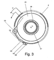
- Each of these consists of a roller of type 32 (element for detaching the wire from the spool along a centrifugal path, given the movement relative to the cylinder 2 imposed on the spool for its unwinding), of the centrifugal retaining eyelet 33, of the pulley 34 (for deviation in the plane perpendicular to the axis 1) and of the final pulley 35 for 90° displacement into a new longitudinal path parallel to the machine axis 1, virtually along a straight generating line of the cylinder 2, along which eyelets, the outline 36 of which can be seen in the drawing, are disposed at regular intervals ( Figure 3 showing a section through the machine in a plane perpendicular to the axis 1).
- each wire continues, in a manner identical to that of normal tubular stranding machines, along its own independent rectilinear trajectory along all the corresponding eyelets of type 36 applied in banks on the outer surface of the cylinder 2 and disposed along the same straight line to define a rectilinear path up to the machine exit, by straddling the intermediate ground supports 9 via through the cavities 37 provided in the rings 38 of the cylinder 2; and straddling the final support 6 via the cavities 39 disposed cone-like within the end rotor 40 supported on the support 6, to arrive undisturbed at the combining die 52 where the stranding action takes place, under the extraction action of the take-up unit 53.
- these linear paths are disposed along those portions of outer surface of the cylinder 2 free of windows.
- this unwinding movement can be obtained by rotating the spool almost at the same speed O as the cylinder 2, by dragging it non-rigidly by it and making it lag behind by the fractional amount p/d by a braking action: and as the required wire quantity is pulled from the outside by the overall take-up unit 53, this take-up unit automatically exerts the necessary braking action.
- the only limitation is that the pull by the take-up unit must not exceed the maximum pull which can be exerted on the wire in order not to damage its performances; this can be controlled by simply limiting the pull to apply, i.e. the maximum dragging action exerted by the cylinder 2 on the spools.
- Spool movement is obtained by simple entrainment action by the cylinder 2 via an apparatus 41 (or 42) fixed rigidly thereto in a suitable position on the respective discs 25 (or 65), able to force a sliding element 67 (or 69) to exert an adjustable pressure against the flange 82 or 83 respectively of the spool which it faces.
- the pressure is adjusted either from the outside by a PLC which feeds its signals to each of the apparatuses of type 41 or 42 by passing through contacts sliding on conducting rings 54; or by on-board control programmable to achieve reduction in braking action proportional to the spool emptying and hence to the reduction in the arm exerted by the unwinding wire.
- the aforedescribed machine is constructed to carry out at two separate times the stranding action (or spool emptying), and the spool filling which is implemented simultaneously for all spools by, when the spools are empty, halting the machine in such a position that an entire linear row of windows 71 suitably faces the loading device 56 of Figure 5 , and then fixing to each spool the correspondent feed wire, passed through the recess 51 facing it; then rotating all the spools until filled, by an external rotation device passed through one of the other two residual recesses to come into contact with each spool; for example ( Figure 5 ) by means of an externally operated roller 49 able to make contact with one or both the spool flanges (or with the spool central drum and with the envelope of the wire wound on it), and then rotating it; and a wire guide 50 which runs along its ground support 55 such as to undergo a path parallel to the axis 1 and hence able to arrange the wire in an ordered manner along the entire length of the s
- the feed wires After filling the spools (which are fixed on the machine and always remain there) the feed wires merely have to be cut and the wire ends of each spool be fixed to the end of the wire previously unwound from it.
- the end of the just unwound spool is halted by a suitable wire absence sensor such that it remains projecting from the unwinding equipment 32+33+34+35 relative to the spool in question, and therefore returns available for this operation, without having to rethread the machine.
- a new stranding cycle then commences.
- the machine structure enables other highly important operations not possible on a normal tubular machine to be carried out, for example, if both the general shaft 3 and all the spool support shafts both of type 27 (right hand) and type 68 (left hand) are hollow, their inner space can be used as a direct passage of wires or cables at rest on the ground, without disturbance by rotation of the machine or, better still, or for the inner insertion of another hollow tube coaxial to the machine axis 1.
- the hollow shaft 19 of Figure 7 at rest with respect to the ground and coaxial to the machine axis 1, passes through the centre of all shafts of type 27 (or 68) which in this case must be hollow, and has an outer diameter such as not to be disturbed by the machine rotation and hence less than the inner diameter of these hollow shafts. It is supported in the following manner: at that end now used as inlet for the entry wires, on the left of the drawing of Figure 7 , by a fixed ground support 57; along the entire length of the machine by bearings 58 and 59 which isolate the rotary hollow shafts 27 and 68, and inserted only if made necessary by the natural flexure of the shaft due to its weight (i.e.
- the bearings are inserted only at those points where they would come into contact with the hollow shafts); at the intermediate support 9, by means of a bearing 60 isolating it from the hollow disc 63; at that end to the right in the drawing of Figure 7 , by a bearing 66 isolating it from the end supporting rotary disc 40.
- the machine can operate as an armouring and screening machine for already formed cables ( Figure 8 ) or as a stranding machine for cables with several layers, each deposited in successive passes through the machine onto the cable under formation during the previous passes; a number of sections of this type of machine can also be arranged in series to form a line able to produce multi-layer cables in a single pass, operating also in tandem if required.
- the nucleus of this machine is exactly identical and it could be said to comprise a machine such as that already described and shown in Figure 7 (however necessarily containing the described static central shaft 19, in the stated manner) but of double length. Hence only those mechanisms additional to this latter and which enable its simultaneous loading will be described.
- this machine can also be considered composed of left hand and right hand spools disposed in pairs, the devices relative of one of these pairs, composed of the left hand spool 64 and right hand spool 23 of Figure 9 , will be described (the numbering of Figure 2 has been preserved for similar components precisely to underline identity in the two cases).
- machine loading takes place only on one of the two series of n spools (for example all those of left hand type such as 64); while the n spools of the other series (in the example the right hand spools such as 23) are subjected to normal stranding movement.
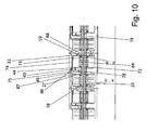
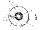
- the spools being filled are driven ( Figures 10 and 11 ) by the action of a device supported by the shaft 19, and hence at rest relative to the ground, and consisting of an electric motor 49 supported by a ring base 78 applied to the hollow shaft 19. It drives the sprocket 43 (supported by the hollow upright 75) by means of a toothed belt transmission adaptable to the two alternative positions, rotated through 180° one to the other, which said hollow upright 75 assumes.
- the sprocket 43 engages the ring gear 44 fixed on the spool flange 72; the wire, fixed to the spool is therefore pulled by it from the feed coils or stempacks by passing within the hollow shaft 19 and therefore is not disturbed by the rotation of the machine.
- the equipments composed of the elements 49+75+43+74+73, which are interposed in each interval between each spool of right hand type 23 or left hand type 64, are able to serve one or the other alternately: in the ring base 78 applied to the hollow shaft 19 which supports them, there is in fact a cross slot into which the upright 75 is drawn and halted by a spring of vertical axis (which enables it to be inserted in two positions rotated through 180° one to the other): the spring has therefore merely to be forced and the equipment rotated through 180° to serve the opposite spool.
- All the entering wires run along the core cylinder 19 through appropriate hollow cylindrical conduits 76 ( Figures 10 and 11 ) of n in number arranged orderly against its inner surface and emerge from them at the appropriate holes 77 provided in it, to run along the hollow upright 75 and arm 74 as far as the distributor wire guide 73 (suitable deviation pulleys are disposed at each bend).
- the machine structure in addition to stranding, also enables the already described screening, laying-up and stranding operations on multi-layer cables, including in tandem, which cannot be done by a normal tubular machine, while being able to be fed continuously during rotation of the cylinder 2.
- an already formed cable has merely to be passed through the free central space of the shaft 19 (or, better still, through an additional likewise hollow shaft 79 coaxial to the general machine shaft 1 and of the same length and likewise supported at its ends by the supports 57 and 40) to enable the machine to operate as a cable armouring and screening machine ( Figure 8 ), or as a stranding machine for cables with several layers, each deposited in successive passes through the machine on cables under formation during the previous passes; a number of sections of this type of machine can also be arranged in series to form a line able to produce multi-layer cables in a single pass, operating also in tandem if required.
- the machine is also much shorter and compact (with a reduction in overall area) and less costly (the elimination or reduction of the number of intermediate ground supports, additional to those indispensable positioned at the machine ends, reduces by a like number the number of very costly bearings of diameter greater than that of the tube, required for each intermediate support).
- the machine of the invention is therefore able to continuously produce, without downtimes, except for the very short times for changing over the roles of the two sets of spools when the stranding spools are empty: this is done by cutting and connecting the entry wires on the empty spools, and connecting the wire ends of the feed spools, filled in the meantime, to the ends of the cable under formation.
Landscapes
- Ropes Or Cables (AREA)
- Processes Specially Adapted For Manufacturing Cables (AREA)
- Unwinding Of Filamentary Materials (AREA)
Claims (5)
- Toronneuse tubulaire comprenant une structure de support constituée d'un cylindre creux (2) qui tourne autour de son axe longitudinal (1), sur des supports (6, 5, 9) fixés au sol, ladite toronneuse tubulaire comprenant également des moyens pour faire tourner ledit cylindre creux (2) autour de son axe longitudinal (1) et le maintenir, ledit cylindre creux (2) comprenant dans sa partie intérieure au moins une unité fonctionnelle constituée d'une bobine (23, 24, 64) agencée pour loger, guider et faire tourner les fils destinés à être toronnés, ladite au moins une bobine (23, 24, 64) ayant son axe longitudinal coïncidant avec ledit axe (1) dudit cylindre creux (2) et étant associé audit cylindre creux (2) par l'intermédiaire de moyens de support permettant à ladite au moins une bobine (23, 24, 64) de tourner indépendamment par rapport audit cylindre creux (2), lesdits moyens de support comprenant au moins une bride ou un disque (25, 65) rigide avec ledit cylindre creux (2) et ayant son axe central coïncidant avec ledit axe (1) dudit cylindre creux (2), au moins un arbre saillant (27, 68) s'étendant à partir de ladite bride ou duquel disque (25, 65) rigidement et de façon axiale avec un axe longitudinal coïncidant avec ledit axe (1) dudit cylindre creux (2), ladite au moins une bobine (23, 24, 64) étant retenue sur ledit arbre saillant (27, 68) de manière indépendante en rotation, caractérisée en ce qu'elle comprend en outre des moyens pour freiner (45, 46) la rotation de ladite au moins une bobine (23, 24, 64) par rapport audit cylindre creux (2), lesdits moyens pour freiner (45, 46) la rotation de ladite au moins une bobine (23, 24, 64) par rapport à audit cylindre creux (2) comprenant des plaquettes de frottement (47, 48) tournant rigidement avec un élément parmi ladite bride ou ledit disque (25, 65) de façon adjacente à ladite au moins une bobine (23, 24, 64) et agencées pour entrer en contact avec ladite au moins une bobine (23, 24, 64) pour créer un frottement entre ladite au moins une bobine (23, 24, 64) et ladite bride ou ledit disque (25, 65).
- Toronneuse tubulaire selon la revendication 1, caractérisée en ce que deux desdits arbres saillants (27, 68) s'étendent à partir de ladite bride ou dudit disque (25, 65), un de chaque côté de ladite bride ou disque (25, 65).
- Toronneuse tubulaire selon une quelconque des revendications précédentes, caractérisée en ce que ledit cylindre creux (2) comprend, positionnée en correspondance avec chacune de ladite au moins une bobine (23, 24, 64), une ouverture ou fenêtre (31, 71) permettant l'accès à ladite au moins une bobine (23, 24, 64) à partir de l'extérieur dudit cylindre (2), et le passage simultané desdits fils vers l'extérieur.
- Toronneuse tubulaire selon la revendication 1, caractérisée en ce que lesdits arbres saillants (27, 68) sont creux.
- Toronneuse tubulaire selon la revendication 4, caractérisé en ce qu'un arbre central statique (19) passe à travers la partie intérieure desdits arbres saillants (27, 68) de façon coaxiale avec ceux-ci.
Applications Claiming Priority (2)
| Application Number | Priority Date | Filing Date | Title |
|---|---|---|---|
| ITMI20040609 | 2004-03-29 | ||
| IT000609A ITMI20040609A1 (it) | 2004-03-29 | 2004-03-29 | Macchina cordatrice tubolare |
Publications (3)
| Publication Number | Publication Date |
|---|---|
| EP1584739A2 EP1584739A2 (fr) | 2005-10-12 |
| EP1584739A3 EP1584739A3 (fr) | 2006-06-07 |
| EP1584739B1 true EP1584739B1 (fr) | 2009-10-21 |
Family
ID=34897787
Family Applications (1)
| Application Number | Title | Priority Date | Filing Date |
|---|---|---|---|
| EP05100465A Expired - Lifetime EP1584739B1 (fr) | 2004-03-29 | 2005-01-25 | Toronneuse tubulaire |
Country Status (5)
| Country | Link |
|---|---|
| EP (1) | EP1584739B1 (fr) |
| AT (1) | ATE446410T1 (fr) |
| DE (1) | DE602005017214D1 (fr) |
| ES (1) | ES2333886T3 (fr) |
| IT (1) | ITMI20040609A1 (fr) |
Families Citing this family (3)
| Publication number | Priority date | Publication date | Assignee | Title |
|---|---|---|---|---|
| CN103397552B (zh) * | 2013-08-02 | 2015-09-30 | 安徽省宁国市天成电机有限公司 | 一种绕线装置 |
| CN107039128A (zh) * | 2017-05-19 | 2017-08-11 | 邵现明 | 一种同心式高速绞线机 |
| CN110277202B (zh) * | 2019-07-10 | 2020-12-08 | 杭州宏峰电缆有限公司 | 一种束丝成缆设备及其生产工艺 |
Family Cites Families (3)
| Publication number | Priority date | Publication date | Assignee | Title |
|---|---|---|---|---|
| GB1001636A (en) * | 1961-09-30 | 1965-08-18 | Aleksander Pilczuk | Device for twisting of wire ropes and flexible shafts |
| IT1165923B (it) * | 1979-12-12 | 1987-04-29 | Pirelli | Macchina cordatrice a bobine centrali |
| DE3609146C2 (de) * | 1986-03-19 | 1997-06-19 | Kabelmetal Electro Gmbh | Einrichtung zum Verseilen oder Aufseilen von Verseilelementen |
-
2004
- 2004-03-29 IT IT000609A patent/ITMI20040609A1/it unknown
-
2005
- 2005-01-25 AT AT05100465T patent/ATE446410T1/de not_active IP Right Cessation
- 2005-01-25 EP EP05100465A patent/EP1584739B1/fr not_active Expired - Lifetime
- 2005-01-25 DE DE602005017214T patent/DE602005017214D1/de not_active Expired - Lifetime
- 2005-01-25 ES ES05100465T patent/ES2333886T3/es not_active Expired - Lifetime
Also Published As
| Publication number | Publication date |
|---|---|
| EP1584739A2 (fr) | 2005-10-12 |
| DE602005017214D1 (de) | 2009-12-03 |
| ITMI20040609A1 (it) | 2004-06-29 |
| EP1584739A3 (fr) | 2006-06-07 |
| ES2333886T3 (es) | 2010-03-02 |
| ATE446410T1 (de) | 2009-11-15 |
Similar Documents
| Publication | Publication Date | Title |
|---|---|---|
| US3997122A (en) | Method and apparatus for wrapping multiple tapes upon an elongated structure | |
| CA1126711A (fr) | Toronneuse a bobines sur axe | |
| US3396522A (en) | Stranding machine | |
| JPS6218250B2 (fr) | ||
| US2216225A (en) | Apparatus for coiling wire or the like | |
| US6223511B1 (en) | Apparatus for helically assembling at least two filaments | |
| KR880001111B1 (ko) | 광파이버의 장력완화 꼬임집합장치 | |
| US1911925A (en) | Wire stranding machine | |
| EP1584739A2 (fr) | Toronneuse tubulaire | |
| US20100170213A1 (en) | Double-Twist Bunching Machine | |
| US4300339A (en) | System for stranding and cabling elongate filaments | |
| JPS5978073A (ja) | ワイヤ巻取り装置 | |
| GB2074623A (en) | Wire rope twisting machine | |
| US4570428A (en) | Twin track buncher | |
| EP0186437A2 (fr) | Toronneuse-câbleuse | |
| US2484055A (en) | Core replacing apparatus and method for stranded cables | |
| EP0461844B1 (fr) | Perfectionnements aux toronneuses | |
| DE102016105072B4 (de) | Bandiereinheit und Verfahren zum Umwickeln eines strangförmigen Guts | |
| FI72831B (fi) | Anordning foer att tvinna aotminstone tvao ledare. | |
| US2709403A (en) | Stranding machine | |
| US6948304B2 (en) | Compact universal concentric strander with take-off sheaves mounted on strander shaft | |
| AU589572B2 (en) | Double twist bow buncher | |
| JP2008507831A (ja) | 長尺巻線材の撚りを行うための装置と方法 | |
| FI79417B (fi) | Bildande av kabelkaernenheter. | |
| JP2009023141A (ja) | タイヤ構成部材の巻付け方法及び装置 |
Legal Events
| Date | Code | Title | Description |
|---|---|---|---|
| PUAI | Public reference made under article 153(3) epc to a published international application that has entered the european phase |
Free format text: ORIGINAL CODE: 0009012 |
|
| AK | Designated contracting states |
Kind code of ref document: A2 Designated state(s): AT BE BG CH CY CZ DE DK EE ES FI FR GB GR HU IE IS IT LI LT LU MC NL PL PT RO SE SI SK TR |
|
| AX | Request for extension of the european patent |
Extension state: AL BA HR LV MK YU |
|
| PUAL | Search report despatched |
Free format text: ORIGINAL CODE: 0009013 |
|
| AK | Designated contracting states |
Kind code of ref document: A3 Designated state(s): AT BE BG CH CY CZ DE DK EE ES FI FR GB GR HU IE IS IT LI LT LU MC NL PL PT RO SE SI SK TR |
|
| AX | Request for extension of the european patent |
Extension state: AL BA HR LV MK YU |
|
| 17P | Request for examination filed |
Effective date: 20061128 |
|
| AKX | Designation fees paid |
Designated state(s): AT BE BG CH CY CZ DE DK EE ES FI FR GB GR HU IE IS IT LI LT LU MC NL PL PT RO SE SI SK TR |
|
| 17Q | First examination report despatched |
Effective date: 20070308 |
|
| RAP1 | Party data changed (applicant data changed or rights of an application transferred) |
Owner name: CORTINOVIS MACHINERY S.P.A. |
|
| GRAP | Despatch of communication of intention to grant a patent |
Free format text: ORIGINAL CODE: EPIDOSNIGR1 |
|
| GRAS | Grant fee paid |
Free format text: ORIGINAL CODE: EPIDOSNIGR3 |
|
| GRAA | (expected) grant |
Free format text: ORIGINAL CODE: 0009210 |
|
| AK | Designated contracting states |
Kind code of ref document: B1 Designated state(s): AT BE BG CH CY CZ DE DK EE ES FI FR GB GR HU IE IS IT LI LT LU MC NL PL PT RO SE SI SK TR |
|
| REG | Reference to a national code |
Ref country code: GB Ref legal event code: FG4D |
|
| REG | Reference to a national code |
Ref country code: CH Ref legal event code: EP |
|
| RAP2 | Party data changed (patent owner data changed or rights of a patent transferred) |
Owner name: CORTINOVIS MACHINERY S.P.A. |
|
| REG | Reference to a national code |
Ref country code: IE Ref legal event code: FG4D |
|
| REF | Corresponds to: |
Ref document number: 602005017214 Country of ref document: DE Date of ref document: 20091203 Kind code of ref document: P |
|
| REG | Reference to a national code |
Ref country code: CH Ref legal event code: NV Representative=s name: R. A. EGLI & CO. PATENTANWAELTE |
|
| NLT2 | Nl: modifications (of names), taken from the european patent patent bulletin |
Owner name: CORTINOVIS MACHINERY S.P.A. Effective date: 20091104 |
|
| REG | Reference to a national code |
Ref country code: ES Ref legal event code: FG2A Ref document number: 2333886 Country of ref document: ES Kind code of ref document: T3 |
|
| LTIE | Lt: invalidation of european patent or patent extension |
Effective date: 20091021 |
|
| NLV1 | Nl: lapsed or annulled due to failure to fulfill the requirements of art. 29p and 29m of the patents act | ||
| PG25 | Lapsed in a contracting state [announced via postgrant information from national office to epo] |
Ref country code: FI Free format text: LAPSE BECAUSE OF FAILURE TO SUBMIT A TRANSLATION OF THE DESCRIPTION OR TO PAY THE FEE WITHIN THE PRESCRIBED TIME-LIMIT Effective date: 20091021 Ref country code: LT Free format text: LAPSE BECAUSE OF FAILURE TO SUBMIT A TRANSLATION OF THE DESCRIPTION OR TO PAY THE FEE WITHIN THE PRESCRIBED TIME-LIMIT Effective date: 20091021 Ref country code: SE Free format text: LAPSE BECAUSE OF FAILURE TO SUBMIT A TRANSLATION OF THE DESCRIPTION OR TO PAY THE FEE WITHIN THE PRESCRIBED TIME-LIMIT Effective date: 20091021 Ref country code: IS Free format text: LAPSE BECAUSE OF FAILURE TO SUBMIT A TRANSLATION OF THE DESCRIPTION OR TO PAY THE FEE WITHIN THE PRESCRIBED TIME-LIMIT Effective date: 20100221 Ref country code: PT Free format text: LAPSE BECAUSE OF FAILURE TO SUBMIT A TRANSLATION OF THE DESCRIPTION OR TO PAY THE FEE WITHIN THE PRESCRIBED TIME-LIMIT Effective date: 20100222 |
|
| PG25 | Lapsed in a contracting state [announced via postgrant information from national office to epo] |
Ref country code: PL Free format text: LAPSE BECAUSE OF FAILURE TO SUBMIT A TRANSLATION OF THE DESCRIPTION OR TO PAY THE FEE WITHIN THE PRESCRIBED TIME-LIMIT Effective date: 20091021 Ref country code: SI Free format text: LAPSE BECAUSE OF FAILURE TO SUBMIT A TRANSLATION OF THE DESCRIPTION OR TO PAY THE FEE WITHIN THE PRESCRIBED TIME-LIMIT Effective date: 20091021 |
|
| PG25 | Lapsed in a contracting state [announced via postgrant information from national office to epo] |
Ref country code: BE Free format text: LAPSE BECAUSE OF FAILURE TO SUBMIT A TRANSLATION OF THE DESCRIPTION OR TO PAY THE FEE WITHIN THE PRESCRIBED TIME-LIMIT Effective date: 20091021 Ref country code: AT Free format text: LAPSE BECAUSE OF FAILURE TO SUBMIT A TRANSLATION OF THE DESCRIPTION OR TO PAY THE FEE WITHIN THE PRESCRIBED TIME-LIMIT Effective date: 20091021 |
|
| PG25 | Lapsed in a contracting state [announced via postgrant information from national office to epo] |
Ref country code: EE Free format text: LAPSE BECAUSE OF FAILURE TO SUBMIT A TRANSLATION OF THE DESCRIPTION OR TO PAY THE FEE WITHIN THE PRESCRIBED TIME-LIMIT Effective date: 20091021 Ref country code: DK Free format text: LAPSE BECAUSE OF FAILURE TO SUBMIT A TRANSLATION OF THE DESCRIPTION OR TO PAY THE FEE WITHIN THE PRESCRIBED TIME-LIMIT Effective date: 20091021 Ref country code: BG Free format text: LAPSE BECAUSE OF FAILURE TO SUBMIT A TRANSLATION OF THE DESCRIPTION OR TO PAY THE FEE WITHIN THE PRESCRIBED TIME-LIMIT Effective date: 20100121 Ref country code: RO Free format text: LAPSE BECAUSE OF FAILURE TO SUBMIT A TRANSLATION OF THE DESCRIPTION OR TO PAY THE FEE WITHIN THE PRESCRIBED TIME-LIMIT Effective date: 20091021 |
|
| PLBE | No opposition filed within time limit |
Free format text: ORIGINAL CODE: 0009261 |
|
| STAA | Information on the status of an ep patent application or granted ep patent |
Free format text: STATUS: NO OPPOSITION FILED WITHIN TIME LIMIT |
|
| PG25 | Lapsed in a contracting state [announced via postgrant information from national office to epo] |
Ref country code: SK Free format text: LAPSE BECAUSE OF FAILURE TO SUBMIT A TRANSLATION OF THE DESCRIPTION OR TO PAY THE FEE WITHIN THE PRESCRIBED TIME-LIMIT Effective date: 20091021 Ref country code: MC Free format text: LAPSE BECAUSE OF NON-PAYMENT OF DUE FEES Effective date: 20100131 Ref country code: CZ Free format text: LAPSE BECAUSE OF FAILURE TO SUBMIT A TRANSLATION OF THE DESCRIPTION OR TO PAY THE FEE WITHIN THE PRESCRIBED TIME-LIMIT Effective date: 20091021 |
|
| 26N | No opposition filed |
Effective date: 20100722 |
|
| GBPC | Gb: european patent ceased through non-payment of renewal fee |
Effective date: 20100125 |
|
| PG25 | Lapsed in a contracting state [announced via postgrant information from national office to epo] |
Ref country code: GR Free format text: LAPSE BECAUSE OF FAILURE TO SUBMIT A TRANSLATION OF THE DESCRIPTION OR TO PAY THE FEE WITHIN THE PRESCRIBED TIME-LIMIT Effective date: 20100122 |
|
| PG25 | Lapsed in a contracting state [announced via postgrant information from national office to epo] |
Ref country code: GB Free format text: LAPSE BECAUSE OF NON-PAYMENT OF DUE FEES Effective date: 20100125 |
|
| PG25 | Lapsed in a contracting state [announced via postgrant information from national office to epo] |
Ref country code: IE Free format text: LAPSE BECAUSE OF NON-PAYMENT OF DUE FEES Effective date: 20100125 |
|
| PGFP | Annual fee paid to national office [announced via postgrant information from national office to epo] |
Ref country code: LU Payment date: 20101223 Year of fee payment: 7 |
|
| PGFP | Annual fee paid to national office [announced via postgrant information from national office to epo] |
Ref country code: DE Payment date: 20110112 Year of fee payment: 7 Ref country code: IT Payment date: 20110124 Year of fee payment: 7 Ref country code: FR Payment date: 20110117 Year of fee payment: 7 |
|
| PGFP | Annual fee paid to national office [announced via postgrant information from national office to epo] |
Ref country code: ES Payment date: 20101230 Year of fee payment: 7 |
|
| PGFP | Annual fee paid to national office [announced via postgrant information from national office to epo] |
Ref country code: CH Payment date: 20110421 Year of fee payment: 7 |
|
| PG25 | Lapsed in a contracting state [announced via postgrant information from national office to epo] |
Ref country code: CY Free format text: LAPSE BECAUSE OF FAILURE TO SUBMIT A TRANSLATION OF THE DESCRIPTION OR TO PAY THE FEE WITHIN THE PRESCRIBED TIME-LIMIT Effective date: 20091021 |
|
| REG | Reference to a national code |
Ref country code: CH Ref legal event code: PL |
|
| PG25 | Lapsed in a contracting state [announced via postgrant information from national office to epo] |
Ref country code: NL Free format text: LAPSE BECAUSE OF FAILURE TO SUBMIT A TRANSLATION OF THE DESCRIPTION OR TO PAY THE FEE WITHIN THE PRESCRIBED TIME-LIMIT Effective date: 20091021 Ref country code: HU Free format text: LAPSE BECAUSE OF FAILURE TO SUBMIT A TRANSLATION OF THE DESCRIPTION OR TO PAY THE FEE WITHIN THE PRESCRIBED TIME-LIMIT Effective date: 20100422 |
|
| REG | Reference to a national code |
Ref country code: FR Ref legal event code: ST Effective date: 20120928 |
|
| PG25 | Lapsed in a contracting state [announced via postgrant information from national office to epo] |
Ref country code: TR Free format text: LAPSE BECAUSE OF FAILURE TO SUBMIT A TRANSLATION OF THE DESCRIPTION OR TO PAY THE FEE WITHIN THE PRESCRIBED TIME-LIMIT Effective date: 20091021 Ref country code: DE Free format text: LAPSE BECAUSE OF NON-PAYMENT OF DUE FEES Effective date: 20120801 Ref country code: LI Free format text: LAPSE BECAUSE OF NON-PAYMENT OF DUE FEES Effective date: 20120131 Ref country code: CH Free format text: LAPSE BECAUSE OF NON-PAYMENT OF DUE FEES Effective date: 20120131 |
|
| REG | Reference to a national code |
Ref country code: DE Ref legal event code: R119 Ref document number: 602005017214 Country of ref document: DE Effective date: 20120801 |
|
| PG25 | Lapsed in a contracting state [announced via postgrant information from national office to epo] |
Ref country code: IT Free format text: LAPSE BECAUSE OF NON-PAYMENT OF DUE FEES Effective date: 20120125 |
|
| PG25 | Lapsed in a contracting state [announced via postgrant information from national office to epo] |
Ref country code: FR Free format text: LAPSE BECAUSE OF NON-PAYMENT OF DUE FEES Effective date: 20120131 |
|
| REG | Reference to a national code |
Ref country code: ES Ref legal event code: FD2A Effective date: 20130705 |
|
| PG25 | Lapsed in a contracting state [announced via postgrant information from national office to epo] |
Ref country code: ES Free format text: LAPSE BECAUSE OF NON-PAYMENT OF DUE FEES Effective date: 20120126 |
|
| PG25 | Lapsed in a contracting state [announced via postgrant information from national office to epo] |
Ref country code: LU Free format text: LAPSE BECAUSE OF NON-PAYMENT OF DUE FEES Effective date: 20120125 |