EP1584827B1 - Carter de turbomachine comportant des palier lisses pour pivots d'aubes fixes à calage variable - Google Patents
Carter de turbomachine comportant des palier lisses pour pivots d'aubes fixes à calage variable Download PDFInfo
- Publication number
- EP1584827B1 EP1584827B1 EP05290734A EP05290734A EP1584827B1 EP 1584827 B1 EP1584827 B1 EP 1584827B1 EP 05290734 A EP05290734 A EP 05290734A EP 05290734 A EP05290734 A EP 05290734A EP 1584827 B1 EP1584827 B1 EP 1584827B1
- Authority
- EP
- European Patent Office
- Prior art keywords
- turbomachine
- casing
- ceramic
- ring
- bushing
- Prior art date
- Legal status (The legal status is an assumption and is not a legal conclusion. Google has not performed a legal analysis and makes no representation as to the accuracy of the status listed.)
- Expired - Lifetime
Links
Images

Classifications
-
- F—MECHANICAL ENGINEERING; LIGHTING; HEATING; WEAPONS; BLASTING
- F16—ENGINEERING ELEMENTS AND UNITS; GENERAL MEASURES FOR PRODUCING AND MAINTAINING EFFECTIVE FUNCTIONING OF MACHINES OR INSTALLATIONS; THERMAL INSULATION IN GENERAL
- F16C—SHAFTS; FLEXIBLE SHAFTS; ELEMENTS OR CRANKSHAFT MECHANISMS; ROTARY BODIES OTHER THAN GEARING ELEMENTS; BEARINGS
- F16C33/00—Parts of bearings; Special methods for making bearings or parts thereof
- F16C33/02—Parts of sliding-contact bearings
- F16C33/04—Brasses; Bushes; Linings
- F16C33/043—Sliding surface consisting mainly of ceramics, cermets or hard carbon, e.g. diamond like carbon [DLC]
-
- F—MECHANICAL ENGINEERING; LIGHTING; HEATING; WEAPONS; BLASTING
- F01—MACHINES OR ENGINES IN GENERAL; ENGINE PLANTS IN GENERAL; STEAM ENGINES
- F01D—NON-POSITIVE DISPLACEMENT MACHINES OR ENGINES, e.g. STEAM TURBINES
- F01D17/00—Regulating or controlling by varying flow
- F01D17/10—Final actuators
- F01D17/12—Final actuators arranged in stator parts
- F01D17/14—Final actuators arranged in stator parts varying effective cross-sectional area of nozzles or guide conduits
- F01D17/16—Final actuators arranged in stator parts varying effective cross-sectional area of nozzles or guide conduits by means of nozzle vanes
- F01D17/162—Final actuators arranged in stator parts varying effective cross-sectional area of nozzles or guide conduits by means of nozzle vanes for axial flow, i.e. the vanes turning around axes which are essentially perpendicular to the rotor centre line
-
- F—MECHANICAL ENGINEERING; LIGHTING; HEATING; WEAPONS; BLASTING
- F05—INDEXING SCHEMES RELATING TO ENGINES OR PUMPS IN VARIOUS SUBCLASSES OF CLASSES F01-F04
- F05C—INDEXING SCHEME RELATING TO MATERIALS, MATERIAL PROPERTIES OR MATERIAL CHARACTERISTICS FOR MACHINES, ENGINES OR PUMPS OTHER THAN NON-POSITIVE-DISPLACEMENT MACHINES OR ENGINES
- F05C2201/00—Metals
- F05C2201/04—Heavy metals
- F05C2201/0433—Iron group; Ferrous alloys, e.g. steel
- F05C2201/0463—Cobalt
-
- F—MECHANICAL ENGINEERING; LIGHTING; HEATING; WEAPONS; BLASTING
- F05—INDEXING SCHEMES RELATING TO ENGINES OR PUMPS IN VARIOUS SUBCLASSES OF CLASSES F01-F04
- F05C—INDEXING SCHEME RELATING TO MATERIALS, MATERIAL PROPERTIES OR MATERIAL CHARACTERISTICS FOR MACHINES, ENGINES OR PUMPS OTHER THAN NON-POSITIVE-DISPLACEMENT MACHINES OR ENGINES
- F05C2201/00—Metals
- F05C2201/04—Heavy metals
- F05C2201/0433—Iron group; Ferrous alloys, e.g. steel
- F05C2201/0466—Nickel
-
- F—MECHANICAL ENGINEERING; LIGHTING; HEATING; WEAPONS; BLASTING
- F05—INDEXING SCHEMES RELATING TO ENGINES OR PUMPS IN VARIOUS SUBCLASSES OF CLASSES F01-F04
- F05D—INDEXING SCHEME FOR ASPECTS RELATING TO NON-POSITIVE-DISPLACEMENT MACHINES OR ENGINES, GAS-TURBINES OR JET-PROPULSION PLANTS
- F05D2230/00—Manufacture
- F05D2230/20—Manufacture essentially without removing material
- F05D2230/23—Manufacture essentially without removing material by permanently joining parts together
- F05D2230/232—Manufacture essentially without removing material by permanently joining parts together by welding
- F05D2230/237—Brazing
-
- F—MECHANICAL ENGINEERING; LIGHTING; HEATING; WEAPONS; BLASTING
- F05—INDEXING SCHEMES RELATING TO ENGINES OR PUMPS IN VARIOUS SUBCLASSES OF CLASSES F01-F04
- F05D—INDEXING SCHEME FOR ASPECTS RELATING TO NON-POSITIVE-DISPLACEMENT MACHINES OR ENGINES, GAS-TURBINES OR JET-PROPULSION PLANTS
- F05D2300/00—Materials; Properties thereof
- F05D2300/20—Oxide or non-oxide ceramics
- F05D2300/21—Oxide ceramics
-
- F—MECHANICAL ENGINEERING; LIGHTING; HEATING; WEAPONS; BLASTING
- F05—INDEXING SCHEMES RELATING TO ENGINES OR PUMPS IN VARIOUS SUBCLASSES OF CLASSES F01-F04
- F05D—INDEXING SCHEME FOR ASPECTS RELATING TO NON-POSITIVE-DISPLACEMENT MACHINES OR ENGINES, GAS-TURBINES OR JET-PROPULSION PLANTS
- F05D2300/00—Materials; Properties thereof
- F05D2300/40—Organic materials
- F05D2300/43—Synthetic polymers, e.g. plastics; Rubber
- F05D2300/434—Polyimides, e.g. AURUM
Definitions
- the invention relates to a turbomachine casing equipped with plain bearings for the passage of vanes of fixed vanes with variable pitch.
- Such a turbomachine casing is also known from the document US 2002/0154991 A .
- one or more crowns of straightening vanes may be variable pitch, that is to say that the angle of attack of these vanes varies depending on the flight conditions, under the control of a servo system which controls the rotation and the axial displacement of a ring connected to the pivots of the vanes of a crown by rods according to predefined parameters.
- a servo system which controls the rotation and the axial displacement of a ring connected to the pivots of the vanes of a crown by rods according to predefined parameters.
- a plain bearing comprising a ceramic sleeve inside which is disposed a pivot based on iron, nickel or cobalt, or a metal pivot covered with a hoop to base of iron, nickel or cobalt, iron, nickel or cobalt oxides created during continuous contact between the pivot of the blade and the sliding bearing acting as a lubricant.
- the object of the invention is to provide a casing with a socket which overcomes the disadvantages mentioned above.
- the invention proposes a turbomachine casing according to claim 1.
- the metal sleeve stiffens the sleeve during assembly of the latter on the housing, which reduces the breakage during this operation. In case of any cracking of the ceramic ring, the pieces will remain attached to the shirt through the solder. In addition, the solder serves as an interface between two materials having a different expansion and just absorb the expansion gaps. Thus, the ceramic / metal bond is more flexible and the ceramic more resistant.
- the ceramic ring can be in one piece and fixed by brazing or made of several pieces fixed by brazing.
- the invention also relates to a turbomachine according to claim 4.
- the pivot is steel or titanium
- the latter further comprises an insert ring made of a metal material based on iron, nickel or cobalt and hooped on the pivot.
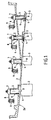
- the figure 1 shows a high-pressure compressor stator of a turbomachine which has an outer casing 2 supporting a plurality of fixed blade crowns 3 of variable pitch.
- the blades 3 extend radially inside the casing 2 in the vein of the gas flow. They have in their radially outer region a plate 4 with circular periphery accommodating in a cavity formed on the inner face 2a of the housing 2, and surmounted by a pivot 5 coaxial with the axis X of the plate 4 housed in a cylindrical orifice 6 through the housing 2.
- the head 7 of the pivot 5 is equipped with an operating arm 8 connected to a control ring 9.
- Each ring of blades is associated with a control ring 9.
- the actuation of a control ring causes the pivoting, in unison, of all the blades 3 of a same ring.
- Each pivot 5 is mounted in an orifice 6 with the interposition of at least one sleeve 10 forming a plain bearing.
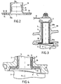
- the figure 2 shows a socket 10 according to the invention.
- This socket 10 comprises a metal jacket 11 whose outer diameter is substantially equal to the diameter of the orifice 6, and a ceramic ring 16 fixed on the inner wall 11a of the jacket 11 by brazing.
- Reference 12 represents the solder layer interposed between the outer face of the ceramic ring 16 and the inner wall 11a of the jacket 11.
- the ceramic of the ring 16 is for example alumina.
- the ring 16 is made by any known method.
- the diameter of the ring 16 is substantially equal and preferably slightly less than the internal diameter of the chamber 11.
- the material constituting the solder 12 is chosen from materials or alloys having a melting temperature lower than the melting temperature of the constituent material. of the shirt 11 and naturally wetting this material as well as the ceramic. It is furthermore chosen from very ductile materials which compress themselves in the cold state and expand hot so that the ceramic is not subjected to any tensile or flexural forces during the temperature variations during compressor operation or during shrinkage. socket 10 in the housing 2 during assembly.
- the ring 16 can be made of several pieces which are soldered to the inner wall 11a of the jacket 11.
- the sleeve 10 advantageously has at one of its ends a flange 13 which extends radially outwards.
- the face 13a of this flange is also equipped by brazing a ceramic washer 14 which ensures the dry friction on the end face of the plate 4.
- FIGS. 3 and 4 show a first embodiment of a sliding bearing 20 for a pivot 5.
- This bearing 20 comprises a lower bearing 20a made by a sleeve 10 according to that described above, and an upper bearing 20b consisting of a sleeve 21 surrounding a sleeve 22 made of a material with a lower coefficient of friction than the ceramic, for example. example polyimide.
- the bushing 10 is located near the plate 4 of the blade 3 and corresponds to the busiest bearing. This bushing allows a large force recovery and a significant limitation of wear on the busiest side of the pivot 5.
- the outer bearing 20b limits the forces of the operating arm 8 and the actuators actuating the control ring 9.
- the reference 30 designates an insert ring based on nickel, cobalt or iron which is hooped on the pivot 5 in the case where the latter is not formed by an alloy having good friction characteristics.
- This insert ring 30 advantageously comprises a flange 31 on the end face of the plate 4.
- FIGS 5 to 7 show a second embodiment of a sliding bearing 20 by a pivot 5, which has a lower bearing 20a and an upper bearing 20b made with sockets 10 according to the sleeve 10 shown on the figure 2 .
Landscapes
- Engineering & Computer Science (AREA)
- General Engineering & Computer Science (AREA)
- Mechanical Engineering (AREA)
- Chemical & Material Sciences (AREA)
- Ceramic Engineering (AREA)
- Structures Of Non-Positive Displacement Pumps (AREA)
- Sliding-Contact Bearings (AREA)
- Turbine Rotor Nozzle Sealing (AREA)
- Support Of The Bearing (AREA)
Description
- L'Invention concerne un carter de turbomachine équipé de paliers lisses pour le passage de pivots d'aubes fixés à calage variable.
- Un tel carter de turbomachine, selon le préambule de la revendication 1, est aussi connu du document
US 2002/0154991 A . - Elle concerne plus précisément une douille à base de céramique destinée à être montée dans un orifice traversant ce carter de turbomachine pour réaliser ce palier lisse d'un pivot d'aube à calage variable.
- Dans un compresseur de turbomachine, et notamment de turboréacteur, une ou plusieurs couronnes d'aubes redresseuses peuvent être à calage variable, c'est-à-dire que l'angle d'attaque de ces aubes varie en fonction des conditions de vol, sous le contrôle d'un système d'asservissement qui commande la rotation et le déplacement axial d'un anneau relié aux pivots des aubes d'une couronne par des biellettes en fonction de paramètres prédéfinis. Ces variations du calage des aubes, associés aux vibrations du carter, entraînent une usure des pièces en contact. Il a été constaté que l'usure est d'autant plus élevée que les décalages angulaires sont petits, et que la fréquence des vibrations est voisine de 160 hz. L'élément le plus nocif est la pression de matage des pivots qui est préjudiciable à la tenue mécanique des pièces.
- Dans le cas d'un système à calage d'aube de turbomachine, Il y a une contrainte particulière qui est la nécessité d'un fonctionnement en milieu non lubrifié. Seule une lubrification sèche peut alors être envisagée pour améliorer les conditions de contact et augmenter la durée de vie des pièces.
- Pour répondre à ces besoins, la demanderesse a proposé dans la demande
FR 03 00435 - Par ailleurs, le document
US 4,410,285 décrit une bague à manchon intérieur en céramique comportant un manchon intermédiaire. - L'un des facteurs limitant l'utilisation de céramiques comme matériau pour douilles est leur fragilité et leur faible ténacité. Il se produit ainsi des casses de douilles lors du montage sur le carter ou en fonctionnement du fait des coefficients de dilatation différents entre le métal du carter et la céramique et des chocs reçus par les systèmes.
- Le but de l'invention est de proposer un carter avec une douille qui pallie les inconvénients mentionnés ci-dessus.
- A cet effet, l'invention propose un carter de turbomachine selon la revendication 1.
- La chemise métallique rigidifie la douille lors du montage de cette dernière sur le carter, ce qui diminue la casse lors de cette opération. En cas de criques éventuelles de la bague en céramique, les morceaux resteront solidaires de la chemise grâce à la brasure. En outre, la brasure sert d'interface entre deux matériaux ayant une dilatation différente et vient absorber les écarts de dilatation. Ainsi, la liaison céramique/métal est plus souple et la céramique plus résistante.
- La bague céramique peut être en une seule pièce et fixée par brasage ou constituée de plusieurs morceaux fixés par brasage.
- L'invention concerne également une turbomachine selon la revendication 4.
- Dans le cas ou le pivot est en acier ou en titane, ce dernier comporte en outre une bague d'insert constituée d'un matériau métallique à base de fer, nickel ou cobalt et frettée sur le pivot.
- D'autres avantages et caractéristiques de l'invention ressortiront à la lecture de la description suivante faite à titre d'exemple et en référence aux dessins annexés, dans lesquels :
- la
figure 1 est une demi-vue en coupe d'un stator de compresseur haute pression d'une turbomachine comportant des couronnes d'aubes de redresseurs à calage variable ; - la
figure 2 est une coupe selon un plan axial d'une douille conforme à l'invention ; - la
figure 3 est une première variante de réalisation d'un palier lisse ; - la
figure 4 est une vue à plus grande échelle du palier inférieur de la variante de lafigure 3 ; - la
figure 5 est une deuxième variante de réalisation de l'invention ; - la
figure 6 est une vue à plus grande échelle du palier supérieur de lafigure 5 ; et
lafigure 7 est une vue à plus grande échelle du palier inférieur de lafigure 5 . - La
figure 1 montre un stator de compresseur haute pression d'une turbomachine qui présente un carter extérieur 2 supportant une pluralité de couronnes d'aubes fixes 3 à calage variable. - Les aubes 3 s'étendent radialement à l'intérieur du carter 2 dans la veine du flux gazeux. Elles présentent dans leur région radialement extérieure une platine 4 à pourtour circulaire logeant dans une cavité ménagée sur la face interne 2a du carter 2, et surmontée d'un pivot 5 coaxiale à l'axe X de la platine 4 logeant dans un orifice cylindrique 6 traversant le carter 2. La tête 7 du pivot 5 est équipée d'un bras de manoeuvre 8 relié à un anneau de commande 9.
- Chaque couronne d'aubes est associée à un anneau de commande 9. L'actionnement d'un anneau de commande entraîne le pivotement, à l'unisson, de toutes les aubes 3 d'une même couronne.
- Chaque pivot 5 est monté dans un orifice 6 avec interposition d'au moins une douille 10 formant un palier lisse.
- La
figure 2 montre une douille 10 conforme à l'invention. Cette douille 10 comporte une chemise métallique 11 dont le diamètre extérieur est sensiblement égal au diamètre de l'orifice 6, et une bague 16 en céramique fixée sur la paroi interne 11a de la chemise 11 par brasage. La référence 12 représente la couche de brasure interposée entre la face externe de la bague 16 en céramique et la paroi interne 11a de la chemise 11. - La céramique de la bague 16 est par exemple de l'alumine. La bague 16 est réalisée par tout procédé connu. Le diamètre de la bague 16 est sensiblement égal et de préférence légèrement inférieur au diamètre intérieur de la chambre 11. Le matériau constitutif de la brasure 12 est choisi parmi les matériaux ou alliages ayant une température de fusion inférieure à la température de fusion du matériau constitutif de la chemise 11 et mouillant naturellement ce matériau ainsi que la céramique. Il est en outre choisi parmi les matériaux très ductiles qui se compriment à froid et se dilatent à chaud afin que la céramique ne soit soumise à aucun effort de traction ou de flexion lors des écarts de températures en fonctionnement du compresseur ou lors du frettage de la douille 10 dans le carter 2 lors du montage.
- La couche de brasure 12 recouvrant toute la surface extérieure de la bague 16, l'apparition éventuelle d'une crique en fonctionnement n'est plus critique, tous les morceaux étant retenus par brasage, les différents morceaux de la bague 16 sont maintenue en position dans la chemise 11, en cas de criques. La bague 16 peut être réalisée en plusieurs morceaux qui sont fixés par brasage sur la paroi interne 11a de la chemise 11.
- La douille 10 présente avantageusement à l'une de ses extrémités une collerette 13 qui s'étend radialement vers l'extérieur. La face 13a de cette collerette est également équipée par brasage d'une rondelle 14 en céramique qui assure le frottement sec sur la face d'extrémité de la platine 4.
- Les
figures 3 et 4 montrent un premier mode de réalisation d'un palier lisse 20 pour un pivot 5. - Ce palier 20 comporte un palier inférieur 20a réalisé par une douille 10 conforme à celle décrite ci-dessus, et un palier supérieur 20b constitué d'une chemise 21 entourant un manchon 22 en un matériau à coefficient de frottement plus faible que la céramique, par exemple en polyimide. La douille 10 est située près de la platine 4 de l'aube 3 et correspond au palier le plus chargé. Cette douille permet une reprise d'effort important et une limitation importante des usures du côté le plus chargé du pivot 5. Le palier extérieur 20b limite les efforts du bras de manoeuvre 8 et des vérins actionnant l'anneau de commande 9.
- La référence 30 désigne une bague d'insert à base de nickel, cobalt ou fer qui est fretté sur le pivot 5 dans le cas où ce dernier n'est pas constitué par un alliage ayant de bonnes caractéristiques en frottement. Cette bague d'insert 30 comporte avantageusement une collerette 31 sur la face d'extrémité de la platine 4.
- Les
figures 5 à 7 montrent un deuxième mode de réalisation d'un palier lisse 20 par un pivot 5, qui présente un palier inférieur 20a et un palier supérieur 20b réalisés avec des douilles 10 conformes à la douille 10 montrée sur lafigure 2 . - Ces deux douilles 10 permettent une meilleure reprise des efforts et une limitation importante du déversement grâce au très bon comportement anti-usure du palier inférieur 20a et du palier supérieur 20b.
Claims (5)
- Carter de turbomachine comportant au moins un orifice cylindrique (6) formant palier lisse pour le passage d'un pivot (5) d'aube fixe (3) à calage variable, ledit orifice cylindrique étant garni intérieurement d'une douille, caractérisé en ce que cette douille est exclusivement constituée des éléments suivants :- une chemise métallique (11) d'une seule pièce cylindrique présentant à l'une de ses extrémités une collerette (13) qui s'étend radialement vers l'extérieur ;- une bague (16) en céramique fixée par brasage sur la paroi interne (11a) de ladite chemise (11); et- une rondelle (14) en céramique fixée par brasage sur la face externe de la collerette (13).
- Carter de turbomachine selon la revendication 1, caractérisée par le fait que la bague en céramique est réalisée en un ou plusieurs morceaux.
- Carter de turbomachine selon la revendication 1 ou 2, caractérisée en ce que ladite douille constitue un palier inférieur (20a) et en ce que ledit orifice cylindrique (6) est garni intérieurement d'une autre douille formant palier supérieur (20b) comprenant une chemise métallique extérieure et une bague en céramique fixée par brasage sur la paroi interne de la chemise.
- Turbomachine, caractérisée en ce qu'elle comprend un carter selon l'une des revendications précédentes.
- Turbomachine selon la revendication 4, caractérisée en ce que ledit carter est celui d'un compresseur.
Applications Claiming Priority (2)
| Application Number | Priority Date | Filing Date | Title |
|---|---|---|---|
| FR0403536 | 2004-04-05 | ||
| FR0403536A FR2868490B1 (fr) | 2004-04-05 | 2004-04-05 | Douille a base de ceramique pour un systeme de calage variable d'aubes de turbomachines |
Publications (2)
| Publication Number | Publication Date |
|---|---|
| EP1584827A1 EP1584827A1 (fr) | 2005-10-12 |
| EP1584827B1 true EP1584827B1 (fr) | 2010-08-04 |
Family
ID=34896711
Family Applications (1)
| Application Number | Title | Priority Date | Filing Date |
|---|---|---|---|
| EP05290734A Expired - Lifetime EP1584827B1 (fr) | 2004-04-05 | 2005-04-04 | Carter de turbomachine comportant des palier lisses pour pivots d'aubes fixes à calage variable |
Country Status (8)
| Country | Link |
|---|---|
| US (1) | US7614846B2 (fr) |
| EP (1) | EP1584827B1 (fr) |
| JP (1) | JP4931363B2 (fr) |
| CA (1) | CA2500942C (fr) |
| DE (1) | DE602005022647D1 (fr) |
| FR (1) | FR2868490B1 (fr) |
| RU (1) | RU2405975C2 (fr) |
| UA (1) | UA93177C2 (fr) |
Families Citing this family (14)
| Publication number | Priority date | Publication date | Assignee | Title |
|---|---|---|---|---|
| FR2892147B1 (fr) * | 2005-10-18 | 2010-09-17 | Snecma | Dispositif de guidage d'aube de stator a calage variable dans une turbomachine axiale |
| US7445427B2 (en) | 2005-12-05 | 2008-11-04 | General Electric Company | Variable stator vane assembly and bushing thereof |
| FR2897639B1 (fr) * | 2006-02-23 | 2010-08-13 | Snecma | Dispositif anti-usure pour systeme de calage variable d'aube d'une turbomachine |
| FR2902822B1 (fr) * | 2006-06-21 | 2008-08-22 | Snecma Sa | Palier pour aube de stator a calage variable |
| EP1925783B1 (fr) * | 2006-11-22 | 2012-05-02 | Siemens Aktiengesellschaft | Montage d'aubage statorique à calage variable |
| FR2913052B1 (fr) | 2007-02-22 | 2011-04-01 | Snecma | Commande des aubes a angle de calage variable |
| US8596035B2 (en) * | 2011-06-29 | 2013-12-03 | Opra Technologies B.V. | Apparatus and method for reducing air mass flow for extended range low emissions combustion for single shaft gas turbines |
| DE102012212998B4 (de) * | 2012-07-24 | 2023-09-07 | Friedrich Boysen Gmbh & Co. Kg | Lagersystem für eine Welle |
| US10302011B2 (en) * | 2015-11-23 | 2019-05-28 | Garrett Transportation I Inc. | Exhaust gas variable turbine assembly |
| DE102017222209A1 (de) * | 2017-12-07 | 2019-06-13 | MTU Aero Engines AG | Leitschaufelanbindung sowie Strömungsmaschine |
| EP3530764B1 (fr) | 2018-02-26 | 2020-08-26 | Roller Bearing Company of America, Inc. | Materiau composite a base d'aluminide de titane auto-lubrifiant |
| US20230003136A1 (en) * | 2021-06-30 | 2023-01-05 | Saint-Gobain Performance Plastics Corporation | Ceramic variable stator vane bushing |
| JP2023166117A (ja) * | 2022-05-09 | 2023-11-21 | 三菱重工業株式会社 | 可変静翼及び圧縮機 |
| BE1032726B1 (fr) * | 2024-06-28 | 2026-02-03 | Safran Aero Boosters | Ensemble redresseur pour compresseur basse pression de turbomachine |
Citations (1)
| Publication number | Priority date | Publication date | Assignee | Title |
|---|---|---|---|---|
| EP1197323A1 (fr) * | 2000-10-10 | 2002-04-17 | Material Sciences Corporation | Structures multicouches de feutre metallique |
Family Cites Families (11)
| Publication number | Priority date | Publication date | Assignee | Title |
|---|---|---|---|---|
| NL75411C (fr) * | 1946-03-20 | |||
| DE2064318A1 (de) * | 1970-12-29 | 1972-07-06 | Motoren Turbinen Union | Lagerung schwenkbarer Leitschaufeln von thermischen Turbomaschinen |
| DE3014645C2 (de) * | 1980-04-16 | 1982-12-02 | MTU Motoren- und Turbinen-Union München GmbH, 8000 München | Metall-Keramik-Bauteil und Verfahren zu seiner Herstellung |
| JPS58163820A (ja) * | 1982-03-19 | 1983-09-28 | Daido Steel Co Ltd | 摺動用部材 |
| CA2082709A1 (fr) * | 1991-12-02 | 1993-06-03 | Srinivasan Venkatasubbu | Aubage de stator a incidence variable pour compresseur a ecoulement axial de turbomachine |
| JPH06109026A (ja) * | 1992-09-24 | 1994-04-19 | Toyota Motor Corp | 高温用軸受構造 |
| JP3733574B2 (ja) * | 1995-05-19 | 2006-01-11 | 石川島播磨重工業株式会社 | ガスタービン用可変静翼のすべり軸受 |
| US6481960B2 (en) * | 2001-03-30 | 2002-11-19 | General Electric Co. | Variable gas turbine compressor vane structure with sintered-and-infiltrated bushing and washer bearings |
| US6767183B2 (en) * | 2002-09-18 | 2004-07-27 | General Electric Company | Methods and apparatus for sealing gas turbine engine variable vane assemblies |
| FR2850138A1 (fr) * | 2003-01-16 | 2004-07-23 | Snecma Moteurs | Dispositif anti-usure pour systeme de calage variable d'aube de turbomachine |
| FR2857692B1 (fr) * | 2003-07-17 | 2007-05-11 | Snecma Moteurs | Systeme de guidage du pivot exterieur d'une aube a angle de calage variable, de stator de turbomachine |
-
2004
- 2004-04-05 FR FR0403536A patent/FR2868490B1/fr not_active Expired - Fee Related
-
2005
- 2005-03-23 CA CA2500942A patent/CA2500942C/fr not_active Expired - Lifetime
- 2005-04-04 DE DE602005022647T patent/DE602005022647D1/de not_active Expired - Lifetime
- 2005-04-04 JP JP2005107283A patent/JP4931363B2/ja not_active Expired - Lifetime
- 2005-04-04 US US11/097,289 patent/US7614846B2/en active Active
- 2005-04-04 RU RU2005109761/06A patent/RU2405975C2/ru active
- 2005-04-04 EP EP05290734A patent/EP1584827B1/fr not_active Expired - Lifetime
- 2005-04-05 UA UAA200503161A patent/UA93177C2/uk unknown
Patent Citations (1)
| Publication number | Priority date | Publication date | Assignee | Title |
|---|---|---|---|---|
| EP1197323A1 (fr) * | 2000-10-10 | 2002-04-17 | Material Sciences Corporation | Structures multicouches de feutre metallique |
Also Published As
| Publication number | Publication date |
|---|---|
| CA2500942C (fr) | 2012-10-23 |
| US7614846B2 (en) | 2009-11-10 |
| RU2005109761A (ru) | 2006-10-10 |
| JP2005291212A (ja) | 2005-10-20 |
| FR2868490A1 (fr) | 2005-10-07 |
| FR2868490B1 (fr) | 2006-07-28 |
| US20050220609A1 (en) | 2005-10-06 |
| JP4931363B2 (ja) | 2012-05-16 |
| CA2500942A1 (fr) | 2005-10-05 |
| EP1584827A1 (fr) | 2005-10-12 |
| RU2405975C2 (ru) | 2010-12-10 |
| DE602005022647D1 (de) | 2010-09-16 |
| UA93177C2 (uk) | 2011-01-25 |
Similar Documents
| Publication | Publication Date | Title |
|---|---|---|
| EP1584827B1 (fr) | Carter de turbomachine comportant des palier lisses pour pivots d'aubes fixes à calage variable | |
| EP3596313B1 (fr) | Ensemble d'anneau de turbine | |
| EP3781792B1 (fr) | Distributeur en cmc avec reprise d'effort par une pince étanche | |
| EP3433471B1 (fr) | Ensemble d'anneau de turbine avec maintien spécifique à froid | |
| EP1870600B1 (fr) | Palier pour pivot d'aube de redresseur à calage variable de turbomachine, aube de redresseur et turbomachine associées | |
| EP2340142B1 (fr) | Procédé d'assemblage de pieces en titane et en acier par soudage diffusion | |
| FR2989991A1 (fr) | Renfort structurel metallique d'aube de turbomachine | |
| EP1717450B1 (fr) | Aube de stator à calage variable, procédé de réparation d'une aube | |
| EP4051879B1 (fr) | Turbine de turbomachine a distributeur en cmc avec reprise d'effort | |
| FR2850138A1 (fr) | Dispositif anti-usure pour systeme de calage variable d'aube de turbomachine | |
| WO2014125221A1 (fr) | Tuyère a divergent mobile avec système de protection thermique | |
| EP1806480B1 (fr) | Dispositif anti-usure pour pivot de guidage d'aube à angle de calage variable de compresseur de turbomachine | |
| EP1777373A1 (fr) | Procédé et système de pilotage de jeu au sommet d'aubes de rotor de turbine dans un moteur à turbine à gaz | |
| WO2020169938A1 (fr) | Procédé de réparation d'une aube d'hélice de turbomachine | |
| EP1748158B1 (fr) | Douille pour pivot d'aube à angle de calage variable pour turbomachine | |
| CA2582621C (fr) | Aube de redresseur a amenagement de forme localise, secteur de redresseurs, etage de compression, compresseur et turbomachine comportant une telle aube | |
| EP4323624B1 (fr) | Turbine de turbomachine a distributeur en cmc avec reprise d'effort et ajustement de position | |
| EP3983650B1 (fr) | Turbine de turbomachine à distributeur en cmc avec reprise d'effort | |
| EP4237665A1 (fr) | Assemblage pour turbine comprenant des secteurs avec languettes d'etancheite lamifiees | |
| FR2857692A1 (fr) | Systeme de guidage du pivot exterieur d'une aube a angle de calage variable, de stator de turbomachine | |
| EP1564381B1 (fr) | Levier de commande du calage angulaire d'une aube dans une turbomachine | |
| FR2897639A1 (fr) | Dispositif anti-usure pour systeme de calage variable d'aube d'une turbomachine | |
| FR3065481A1 (fr) | Ensemble pour turbine, notamment pour une turbomachine | |
| BE1032726B1 (fr) | Ensemble redresseur pour compresseur basse pression de turbomachine | |
| FR3088374A1 (fr) | Guignol pour turbomachine |
Legal Events
| Date | Code | Title | Description |
|---|---|---|---|
| PUAI | Public reference made under article 153(3) epc to a published international application that has entered the european phase |
Free format text: ORIGINAL CODE: 0009012 |
|
| 17P | Request for examination filed |
Effective date: 20050409 |
|
| AK | Designated contracting states |
Kind code of ref document: A1 Designated state(s): AT BE BG CH CY CZ DE DK EE ES FI FR GB GR HU IE IS IT LI LT LU MC NL PL PT RO SE SI SK TR |
|
| AX | Request for extension of the european patent |
Extension state: AL BA HR LV MK YU |
|
| AKX | Designation fees paid |
Designated state(s): DE FR GB IT SE |
|
| 17Q | First examination report despatched |
Effective date: 20060710 |
|
| 17Q | First examination report despatched |
Effective date: 20060710 |
|
| GRAP | Despatch of communication of intention to grant a patent |
Free format text: ORIGINAL CODE: EPIDOSNIGR1 |
|
| RTI1 | Title (correction) |
Free format text: TURBOMACHINE CASING COMPRISING SLIDING BEARINGS FOR PIVOTS OF VARIABLE VANE ASSEMBLY |
|
| GRAJ | Information related to disapproval of communication of intention to grant by the applicant or resumption of examination proceedings by the epo deleted |
Free format text: ORIGINAL CODE: EPIDOSDIGR1 |
|
| GRAP | Despatch of communication of intention to grant a patent |
Free format text: ORIGINAL CODE: EPIDOSNIGR1 |
|
| GRAS | Grant fee paid |
Free format text: ORIGINAL CODE: EPIDOSNIGR3 |
|
| GRAA | (expected) grant |
Free format text: ORIGINAL CODE: 0009210 |
|
| AK | Designated contracting states |
Kind code of ref document: B1 Designated state(s): DE FR GB IT SE |
|
| REG | Reference to a national code |
Ref country code: GB Ref legal event code: FG4D Free format text: NOT ENGLISH |
|
| REF | Corresponds to: |
Ref document number: 602005022647 Country of ref document: DE Date of ref document: 20100916 Kind code of ref document: P |
|
| REG | Reference to a national code |
Ref country code: SE Ref legal event code: TRGR |
|
| PLBE | No opposition filed within time limit |
Free format text: ORIGINAL CODE: 0009261 |
|
| STAA | Information on the status of an ep patent application or granted ep patent |
Free format text: STATUS: NO OPPOSITION FILED WITHIN TIME LIMIT |
|
| 26N | No opposition filed |
Effective date: 20110506 |
|
| REG | Reference to a national code |
Ref country code: DE Ref legal event code: R097 Ref document number: 602005022647 Country of ref document: DE Effective date: 20110506 |
|
| REG | Reference to a national code |
Ref country code: FR Ref legal event code: PLFP Year of fee payment: 12 |
|
| REG | Reference to a national code |
Ref country code: FR Ref legal event code: PLFP Year of fee payment: 13 |
|
| REG | Reference to a national code |
Ref country code: FR Ref legal event code: PLFP Year of fee payment: 14 |
|
| REG | Reference to a national code |
Ref country code: FR Ref legal event code: CD Owner name: SAFRAN AIRCRAFT ENGINES, FR Effective date: 20170719 |
|
| PGFP | Annual fee paid to national office [announced via postgrant information from national office to epo] |
Ref country code: GB Payment date: 20240320 Year of fee payment: 20 |
|
| PGFP | Annual fee paid to national office [announced via postgrant information from national office to epo] |
Ref country code: SE Payment date: 20240320 Year of fee payment: 20 Ref country code: IT Payment date: 20240320 Year of fee payment: 20 Ref country code: FR Payment date: 20240320 Year of fee payment: 20 |
|
| PGFP | Annual fee paid to national office [announced via postgrant information from national office to epo] |
Ref country code: DE Payment date: 20240320 Year of fee payment: 20 |
|
| REG | Reference to a national code |
Ref country code: DE Ref legal event code: R071 Ref document number: 602005022647 Country of ref document: DE |
|
| REG | Reference to a national code |
Ref country code: GB Ref legal event code: PE20 Expiry date: 20250403 |
|
| REG | Reference to a national code |
Ref country code: SE Ref legal event code: EUG |
|
| PG25 | Lapsed in a contracting state [announced via postgrant information from national office to epo] |
Ref country code: GB Free format text: LAPSE BECAUSE OF EXPIRATION OF PROTECTION Effective date: 20250403 |