EP1584855B1 - Structure de raccordement de tuyau - Google Patents
Structure de raccordement de tuyau Download PDFInfo
- Publication number
- EP1584855B1 EP1584855B1 EP05007750A EP05007750A EP1584855B1 EP 1584855 B1 EP1584855 B1 EP 1584855B1 EP 05007750 A EP05007750 A EP 05007750A EP 05007750 A EP05007750 A EP 05007750A EP 1584855 B1 EP1584855 B1 EP 1584855B1
- Authority
- EP
- European Patent Office
- Prior art keywords
- collar
- pipe
- recess
- peripheral wall
- connection structure
- Prior art date
- Legal status (The legal status is an assumption and is not a legal conclusion. Google has not performed a legal analysis and makes no representation as to the accuracy of the status listed.)
- Expired - Lifetime
Links
- 230000002093 peripheral effect Effects 0.000 claims description 31
- 238000005520 cutting process Methods 0.000 claims description 8
- 238000000034 method Methods 0.000 description 14
- 238000010586 diagram Methods 0.000 description 11
- 230000000052 comparative effect Effects 0.000 description 7
- 230000000694 effects Effects 0.000 description 4
- 230000014759 maintenance of location Effects 0.000 description 3
- 230000004048 modification Effects 0.000 description 3
- 238000012986 modification Methods 0.000 description 3
- 230000008901 benefit Effects 0.000 description 2
- 238000003780 insertion Methods 0.000 description 2
- 230000037431 insertion Effects 0.000 description 2
- 239000007788 liquid Substances 0.000 description 2
- 238000004080 punching Methods 0.000 description 2
- 241000009298 Trigla lyra Species 0.000 description 1
- 238000004378 air conditioning Methods 0.000 description 1
- 238000005452 bending Methods 0.000 description 1
- 230000001419 dependent effect Effects 0.000 description 1
- 238000004519 manufacturing process Methods 0.000 description 1
- 238000003825 pressing Methods 0.000 description 1
- 230000008569 process Effects 0.000 description 1
- 230000009467 reduction Effects 0.000 description 1
- 239000003507 refrigerant Substances 0.000 description 1
- 238000007789 sealing Methods 0.000 description 1
Images





Classifications
-
- F—MECHANICAL ENGINEERING; LIGHTING; HEATING; WEAPONS; BLASTING
- F16—ENGINEERING ELEMENTS AND UNITS; GENERAL MEASURES FOR PRODUCING AND MAINTAINING EFFECTIVE FUNCTIONING OF MACHINES OR INSTALLATIONS; THERMAL INSULATION IN GENERAL
- F16L—PIPES; JOINTS OR FITTINGS FOR PIPES; SUPPORTS FOR PIPES, CABLES OR PROTECTIVE TUBING; MEANS FOR THERMAL INSULATION IN GENERAL
- F16L41/00—Branching pipes; Joining pipes to walls
- F16L41/08—Joining pipes to walls or pipes, the joined pipe axis being perpendicular to the plane of a wall or to the axis of another pipe
- F16L41/082—Non-disconnectable joints, e.g. soldered, adhesive or caulked joints
-
- F—MECHANICAL ENGINEERING; LIGHTING; HEATING; WEAPONS; BLASTING
- F28—HEAT EXCHANGE IN GENERAL
- F28F—DETAILS OF HEAT-EXCHANGE AND HEAT-TRANSFER APPARATUS, OF GENERAL APPLICATION
- F28F9/00—Casings; Header boxes; Auxiliary supports for elements; Auxiliary members within casings
- F28F9/26—Arrangements for connecting different sections of heat-exchange elements, e.g. of radiators
- F28F9/262—Arrangements for connecting different sections of heat-exchange elements, e.g. of radiators for radiators
Definitions
- the present invention relates to a pipe connecting structure according to the preamble of independent claim 1.
- a pipe connecting structure can be taken from prior art document JP 05-141580 .
- Japanese Patent No. 2591388 discloses a structure for connecting a pipe to a passage in a block-shaped expansion valve.
- Japanese Published Unexamined Patent Application No. H7-329549 discloses a structure for connecting a pipe to an opening in a block-shaped cap of a liquid tank.
- Japanese Published Unexamined Patent Application No. H5-141580 discloses a structure for connecting a pipe to a bore in a block-shaped connector.
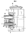
- FIG. 1 is a diagram illustrating an expansion valve to which a pipe connection structure of a first embodiment is applied.
- FIG. 7 is an enlarged cross-sectional view of the same pipe connection structure.
- a pipe 30, through which a refrigerant flows, is connected to a passage 22 formed in a block 21 of an expansion valve 20 as shown in FIGS. 1 and 7.
- the pipe 30 includes a circular cross-section pipe body 30a, an end portion 30b provided at an end of the pipe body 30a, and a collar (flange) 31 extended radially outwardly from the end portion 30b.
- an O-ring 32 is fitted on the end portion 30b of the pipe 10.
- the block 21 includes the passage 22 formed with substantially the same diameter as the end portion 30b of the pipe 30 inserted thereinto, a recess 24 formed in an open end 23 of the passage 22 for receiving the collar 31 of the pipe 30, and a peripheral wall 25 formed around the outer periphery of the recess 24 and deformed inwardly by a tool and fitted onto the collar 31.
- the passage 22 and the recess 24 are circular in cross-section.
- the recess 24 is formed with a lager diameter than the passage 22.
- the collar 31 is held between a bottom surface 24a of the recess 24 and the deformed peripheral wall 25 in the block 21 so that the pipe 30 is secured to the block 21.
- the collar 31 of the pipe 30 is asymmetrical with respect to the thickness center line Z of the caller 31.
- the collar 31 of the pipe 30 does not have a symmetrical thickness with respect to the center line Z of the collar 31, unlike a pipe connection structure in a comparative example in FIGS. 18A and 18B.
- the largest outside diameter portion 31c of the collar 31 is located closer to the end of the pipe 30 than the thickness center line Z of the collar 31.
- the largest outside diameter portion 31c of the collar 31 is located closer to the bottom surface 24a of the recess 24 in the connection shown in FIGS. 5 through 7 than the thickness center line Z of the collar 31. Consequently, an upper surface 31a of the collar 31 (that is, a surface located closer to the pipe body 30a than the largest outside diameter portion 31c and located on the peripheral wall 25 in a connected state shown in FIGS.
- the upper surface 31a of the collar 31 includes a flat surface and a smooth circular arc portion 35.
- the flat portion 34 is located around the inner periphery.
- the circular arc portion 35 extends from the flat portion to the largest outside diameter portion 31c.
- the radius of curvature of the circular arc portion 35 is greater than T/2, and is substantially equal to T in this embodiment.
- Reference T denotes the thickness of the collar 31.
- the pipe 30 and the block 21 are formed in their respective predetermined shapes.
- the working of the pipe 30 includes a plurality of steps, through which the collar 31 is formed on the end portion 30b of the pipe 30 in a conventional manner (e.g., see FIGS. 10 through 13 in Japanese Published Unexamined Patent Application No. H5-141580 ) .
- the collar 31 is symmetrical with respect to the thickness center line z.
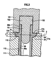
- the collar 31 is formed asymmetrically with respect to the thickness center line Z as shown in FIGS. 3.
- the pipe 30 is held by a clamp 111.
- the clamp 111 is formed with a retention bore 112. In an open end of the retention bore 112, an expanded diameter portion 113, larger in diameter than the retention bore 112, is provided.
- the expanded diameter portion 113 is formed in a circular arc shape in cross section.
- a core bar 121 having an outside diameter equal to the inside diameter of the pipe 30 is fitted into the end portion of the pipe 30.
- the core bar 121 is provided at one end thereof with a large diameter portion 122, at which the core bar 121 is engaged with the end portion of the pipe 30.
- the end portion of the pipe 30, together with the core bar 121 is punched by the punch 131.
- the punch 131 is provided with an insertion bore 132 into which the core bar 121 and the end portion of the pipe 30 are inserted during punching.
- the insertion bore 132 has a diameter substantially equal to the outside diameter of the end portion 30b of the pipe 30.
- the collar 31 is pressed between a distal end face 133 of the punch 131 and the expanded diameter portion 113 of the clamp 111, and is formed in a desired shape of the collar 31.
- a sealing O-ring 32 is fitted on the end portion 30b of the pipe 30 to obtain a pipe 30 having the desired shape.
- the recess 24 is formed by cutting the inner sides of the passage 22 of the block 21. With this operation, a block with desired passage shape is obtained.
- the recess 24 is formed in the open end 23 of the passage 22, and is formed with a larger in diameter than the passage 22.
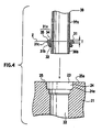
- the prepared pipe 30 is connected to the cut block 21. Specifically, as shown in FIG. 5, the end portion of the pipe 30 is inserted into the open end 23 of the passage 22 in the block 21.
- the O-ring 32, fitted on the periphery of the end portion of the pipe 30, is in pressing contact with the inner periphery of the passage 22, and the collar 31 of the pipe 30 is received in the recess 24.
- the inner peripheral surface of the recess 24 is in proximity to the largest outside diameter portion 31c.
- the collar 31 is located below an upper end face 25a of the peripheral wall 25 within the recess 24.
- connection by a blade tool 40 is carried out as shown in FIG. 6.
- an annular blade portion 41 is pressed into the upper end face 25a of the peripheral wall 25 of the recess 24.
- the peripheral wall 25 is cut as a thin wall, and is bent and deformed inwardly to be press fitted onto the collar 31 so that the pipe 30 is connected to the block 21.
- the annular blade portion 41 includes, on the inner periphery thereof, an inclined surface 42 in a circular arc shape for inwardly bending and deforming the peripheral wall 25.
- the peripheral wall 25 is attached to the upper surface 31a more firmly than in the case of forming the upper surface 31a in a linear shape. Consequently, the strength of the bonding force between the collar 31 and the deformed peripheral wall 25 is further increased.
- peripheral wall 25 is cut in a thin wall shape from an outer periphery thereof while being bent and deformed inwardly by the blade tool 40 to press-fit the peripheral wall 25 onto the collar 31, it is not necessary to previously cut out a cylindrical portion (corresponding to reference 51 in FIG. 14) by a cutting tool, such as an end mill, (corresponding to reference 16 in FIG. 13) around the periphery of the recess 24. This eliminates a large volume of cutting by an end mill, and reduces the manufacturing cost.
- a cutting tool such as an end mill
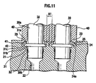
- a distance H1 between two recesses 24 only needs to be at least large enough to be cut into two peripheral walls 25 (about twice the thickness of the peripheral walls 25).
- the clearance between the two passages 22 in the block 21 can be reduced.
- the two recesses 24 may alternatively be overlapped with each other so as to further reduce the distance between the passages 22.
- a blade tool may have a blade portion 41A with a interval at a position corresponding to the overlapped area, and the overlapped area is not caulked.
- FIGS. 8 and 10 illustrate an example of the blade tool 40 in the first embodiment.
- a blade tool 40A in FIG. 8 includes a circumferentially continuous annular blade portion 41A.
- the blade portion 41A includes an outer peripheral cylindrical surface 41a parallel to the central axis L of the cylindrical body.
- the blade portion 41A has a blade edge 41b with a small thickness t continuous to the distal end of the peripheral cylindrical surface 41a.
- the blade portion 41A has an inclined surface 42 continuous to the inner periphery of the blade edge 41b.
- the inclined surface 42 is curved in a concave shape with a predetermined curvature R. This allows the peripheral wall 25 to securely fasten the collar 31.
- the center of curvature 41e is located at the same height as that of the cutting edge 41b.
- the inclined surface 42 may alternatively be either linear or curved in a convex shape. However, it is preferable that the inclined surface 42 be curved in a concave circular arc shape as shown in FIGS. 8 and 10.
- FIG. 10 illustrates another example of the blade tool 40.
- a blade tool 40B in Fig.10A and 10B has a plurality of blade portions 41B arranged at equal intervals in a circumferential direction. It is preferable to set the number of blade portions 41B to any number that allows arrangement of the blade portions at equal interval along the circumferential direction, but the number is not limited to a specific number.
- a section of each blade portion 41B is similar to that shown in Fig.9.
- the peripheral wall 25 of the recess 24 can be cut in a continuously annular thin cylindrical shape, and the entire periphery of the collar 31 can be firmly caulked.
- the peripheral wall 25 of the recess 24 is cut in a thin cylindrical wall by the intermittently arranged blade portion 41B, and the collar 31 can be easily caulked by a small force.
- FIG. 12 illustrates a connection structure for a pipe 30 in a second embodiment.
- Components identical to those in the first embodiment are given the same reference numerals in the embodiment below, and their configurations, functions and effects will not be described.
- the second embodiment is the same as the first embodiment in that the largest outside diameter portion 31c of a collar 31B is decentered toward a bottom surface 24a of a recess 24 as in the first embodiment.
- the collar 31B is different in shape from the collar 31 in the first embodiment.
- a lower surface 31b of the collar 31B is expanded from the distal end side to the proximal end side of the pipe 30 in a tapered shape.
- the bottom surface 24a of the recess 24 is provided with a tapered portion 24c on which the tapered lower surface 31b of the collar 31B abuts.
- the second embodiment provides the same functions and effects as the first embodiment.
- the second embodiment achieves a further result that the tapered portion 24c facilitates the alignment of the central axis of the pipe 30 with the central axis of a passage 22.
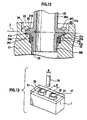
- a portion 17 in an end face of a block 1 is removed by an end mill 16, leaving cylindrical portions 51.
- the clearance H between the two adjacent cylindrical portions 51 is set greater than the outside diameter d of the end mill 16 as shown in FIG. 13.
- the cylindrical portions (peripheral walls) 51 are previously cut out by the end mill 16 around the peripheries of recesses 22 in the block 21 as shown in FIG. 13, and then, as shown in FIGS. 14, 15 and 16, each cylindrical portion 51 is bent and deformed inwardly by a punch 15 to be fitted onto a collar 31.
- the pipe connection structure and connection method in the third embodiment also provide the same functions and effects as the first embodiment.
- a pipe 30 extends through a passage 22 in a block 21.
- the fourth embodiment also provides the same advantages as the first and second embodiments.
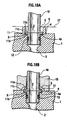
- reference numeral 1 denotes a block; reference numeral 2, a passage formed in the block 1; reference numeral 3, an open end of the passage 2; reference numeral 4, a recess formed in the open end 3 of the passage 2 that is larger in diameter than the passage 2; reference numeral 5, a cylindrical portion provided around the periphery of the recess 4; reference numeral 10, a pipe; reference numeral 11, a collar formed on the periphery of the end portion of the pipe 10; and reference numeral 12, an O-ring fitted on the periphery of the pipe 10.
- This comparative example is different from the first through fourth embodiments in that the largest outside diameter portion of the collar 11 is located in the thickness center line Z of the collar 11.
- the pipe 10 is inserted into the open end 3 of the passage 2 in the block 1 to insert the collar 11 of the pipe 10 in the recess 4. Then, as shown in FIG. 18B, the cylindrical portion 5 is bent and deformed inwardly by a punch 15 to fit the cylindrical portion 5 onto the collar 11.
- the portion of the lower surface of the collar, not contacting the bottom surface of the recess, has a reduced area, while the upper surface of the collar closely contacting the deformed peripheral wall has an increased area.
Landscapes
- Engineering & Computer Science (AREA)
- General Engineering & Computer Science (AREA)
- Mechanical Engineering (AREA)
- Physics & Mathematics (AREA)
- Thermal Sciences (AREA)
- Non-Disconnectible Joints And Screw-Threaded Joints (AREA)
- Branch Pipes, Bends, And The Like (AREA)
- Mutual Connection Of Rods And Tubes (AREA)
Claims (4)
- Structure de raccordement de tuyau, comprenant :un tuyau (30) comprenant un corps de tuyau (30a), une partie d'extrémité (30b) et un collier (31, 31B) s'étendant radialement vers l'extérieur depuis la partie d'extrémité (30b) ; etun bloc (21) comprenant un passage (22) configuré pour recevoir la partie d'extrémité (30b) du tuyau (30) ; un renfoncement (24) formé dans une extrémité ouverte (23) du passage (22) pour recevoir le collier (31, 31B) du tuyau (30) ; et une paroi périphérique (25, 51) du renfoncement (24) configurée pour être déformée vers l'intérieur et ajustée sur le collier (31) ;ledit collier (31, 31B) étant doté d'une partie arquée (35) définissant une partie de diamètre extérieur maximal (31c) du collier (31),caractérisée en ce que
ladite partie de diamètre extérieur maximal (31c) du collier (31) est décentrée vers une surface de fond (24a) du renfoncement (24). - Structure de raccordement de tuyau selon la revendication 1, caractérisée en ce que le collier (31, 31B) comprend une surface inférieure (31b) située plus près de la surface de fond (24a) du renfoncement (24) que la partie de diamètre extérieur maximal (31c) ; et une surface supérieure (31a) située plus près de la paroi périphérique déformée (25, 51) que la partie de diamètre extérieur maximal (31c) ; et
la surface supérieure (31a) comprend la partie arquée (35) s'étendant en forme d'arc circulaire régulier depuis la partie de diamètre extérieur maximal (31c). - Structure de raccordement de tuyau selon la revendication 1 ou 2, caractérisée en ce que la paroi périphérique (51) ajustée sur le collier (31) est une partie cylindrique (51) formée sur la périphérie extérieure du renfoncement (24) par un outil de coupe, et pliée et déformée vers l'intérieur par un mandrin (15).
- Structure de raccordement de tuyau selon la revendication 1 ou 2, caractérisée en ce que la paroi périphérique (25) ajustée sur le collier (31) est une paroi périphérique (25) du renfoncement (24) coupée en une fine paroi par un outil à lame (40, 40A, 40B) tout en étant pliée et déformée vers l'intérieur.
Applications Claiming Priority (2)
| Application Number | Priority Date | Filing Date | Title |
|---|---|---|---|
| JP2004115568A JP2005299774A (ja) | 2004-04-09 | 2004-04-09 | パイプの接続構造 |
| JP2004115568 | 2004-04-09 |
Publications (2)
| Publication Number | Publication Date |
|---|---|
| EP1584855A1 EP1584855A1 (fr) | 2005-10-12 |
| EP1584855B1 true EP1584855B1 (fr) | 2007-11-21 |
Family
ID=34909541
Family Applications (1)
| Application Number | Title | Priority Date | Filing Date |
|---|---|---|---|
| EP05007750A Expired - Lifetime EP1584855B1 (fr) | 2004-04-09 | 2005-04-08 | Structure de raccordement de tuyau |
Country Status (4)
| Country | Link |
|---|---|
| US (1) | US7344164B2 (fr) |
| EP (1) | EP1584855B1 (fr) |
| JP (1) | JP2005299774A (fr) |
| CN (1) | CN1680742A (fr) |
Families Citing this family (11)
| Publication number | Priority date | Publication date | Assignee | Title |
|---|---|---|---|---|
| JP4797998B2 (ja) * | 2006-02-17 | 2011-10-19 | 株式会社デンソー | 熱交換器の配管継手構造及び熱交換器の配管組み付け方法 |
| DE102006024992A1 (de) * | 2006-05-30 | 2007-12-06 | Contitech Techno-Chemie Gmbh | Halterung für eine Rohrleitung |
| JP2009138909A (ja) * | 2007-12-10 | 2009-06-25 | Denso Corp | 配管継手装置 |
| KR101021410B1 (ko) * | 2008-09-18 | 2011-03-14 | 엘에스엠트론 주식회사 | 접속 금구 및 이를 이용한 튜브와 호스의 연결구조 |
| DE102011086322A1 (de) * | 2011-11-14 | 2013-05-16 | Behr Gmbh & Co. Kg | Bauteil, insbesondere Expansionsorgan, mit Rohren und ein Verfahren zur Verbindung |
| FR2988169B1 (fr) * | 2012-03-19 | 2014-04-18 | Dana Canada Corp | Ensemble raccord brase |
| US9777878B2 (en) | 2012-08-31 | 2017-10-03 | Hanon Systems | Connector |
| US10844975B2 (en) | 2016-06-06 | 2020-11-24 | Parker-Hannifin Corporation | Slide through fitting |
| CN111448412A (zh) * | 2017-09-19 | 2020-07-24 | 东莞好奇智能科技有限公司 | 流体分流器 |
| GB201807982D0 (en) * | 2018-05-16 | 2018-07-04 | Bend All Automotive Incorporated | Tube mounting assembly with radial staking, method of assembly |
| KR20250072351A (ko) * | 2023-11-16 | 2025-05-23 | 주식회사 화승알앤에이 | 파이프 블록을 포함하는 배관 시스템 |
Family Cites Families (10)
| Publication number | Priority date | Publication date | Assignee | Title |
|---|---|---|---|---|
| US3374014A (en) * | 1965-07-27 | 1968-03-19 | Standard Pressed Steel Co | Swaged seals |
| US3930298A (en) * | 1973-12-17 | 1976-01-06 | Universal Refrigeration, Inc. | Method of forming a tube fitting assembly |
| DE3816749A1 (de) | 1988-05-17 | 1989-11-30 | Teves Gmbh Alfred | Vorrichtung fuer einen hydraulischen anschluss |
| JP2591388B2 (ja) | 1991-11-15 | 1997-03-19 | 株式会社デンソー | 配管接続装置 |
| US5774982A (en) | 1994-03-16 | 1998-07-07 | Eaton Corporation | Conduit attachment to receiver/drier or accumulator |
| JP3208992B2 (ja) | 1994-06-07 | 2001-09-17 | 株式会社デンソー | 車両用空調装置 |
| US5596881A (en) | 1995-02-22 | 1997-01-28 | Parker-Hannifin Corporation | Pick-up tube attachment technique |
| US5833280A (en) * | 1996-02-26 | 1998-11-10 | Lincoln Brass Works, Inc. | Mechanical joint |
| US5743571A (en) * | 1997-02-18 | 1998-04-28 | Seawin, Inc. | Fitting with floating tube support and method of manufacture |
| US6868684B2 (en) * | 2002-12-17 | 2005-03-22 | Parker-Hannifin Corporation | Block valve with integral refrigerant lines |
-
2004
- 2004-04-09 JP JP2004115568A patent/JP2005299774A/ja active Pending
-
2005
- 2005-04-08 EP EP05007750A patent/EP1584855B1/fr not_active Expired - Lifetime
- 2005-04-08 CN CN200510063540.5A patent/CN1680742A/zh active Pending
- 2005-04-08 US US11/101,642 patent/US7344164B2/en not_active Expired - Fee Related
Also Published As
| Publication number | Publication date |
|---|---|
| US7344164B2 (en) | 2008-03-18 |
| CN1680742A (zh) | 2005-10-12 |
| EP1584855A1 (fr) | 2005-10-12 |
| JP2005299774A (ja) | 2005-10-27 |
| US20050242575A1 (en) | 2005-11-03 |
Similar Documents
| Publication | Publication Date | Title |
|---|---|---|
| US7425021B2 (en) | Pipe joint structure | |
| US7469934B2 (en) | Pipe joint structure and method for fabricating the same | |
| EP0745824B1 (fr) | Echangeur de chaleur et méthode pour sa fabrication | |
| JP2003524132A (ja) | 挿入された管端とプレス連結させるための、取付け又は据え付け部品 | |
| US7344164B2 (en) | Pipe connection structure | |
| US7364208B2 (en) | Structure for connecting two members, method therefor, and die | |
| US20060119098A1 (en) | Pipe Joint Structures and Methods of Manufacturing Such Stuctures | |
| JPS6134003B2 (fr) | ||
| GB2455443A (en) | Pipe member and method of manufacturing the same | |
| US20030080564A1 (en) | Pipe joint assembly and method for assembling the same | |
| EP1692426B1 (fr) | Raccord de tube a montage rapide | |
| US7086668B2 (en) | Coupling assembly | |
| JP2003034106A (ja) | アクスルハウジング及びその製造方法 | |
| US20060208479A1 (en) | Pipe unit with connector and producing method thereof | |
| EP0974023B1 (fr) | Méthode de fabrication et de montage de raccords à tube | |
| JP2002346690A (ja) | 金属部品の鍛造成形方法 | |
| ZA200406340B (en) | Method for producing a cover that can be placed on the end of a motor vehicle exhaust pipe, and a cover produced according to this method | |
| JP2005076741A (ja) | 配管継手構造およびその製造方法 | |
| US20020134194A1 (en) | Axle housing cover with variable thickness | |
| JPH08261378A (ja) | フランジ付軸シール型ニップル | |
| JP4114572B2 (ja) | 配管継手構造の製造方法 | |
| JP2006300292A (ja) | パイプの接続構造 | |
| JP4296883B2 (ja) | 口金具及びその製造方法 | |
| JP3122182U (ja) | リング可撓管継手 | |
| JPH109468A (ja) | ホース用口金具及びブレーキホース |
Legal Events
| Date | Code | Title | Description |
|---|---|---|---|
| PUAI | Public reference made under article 153(3) epc to a published international application that has entered the european phase |
Free format text: ORIGINAL CODE: 0009012 |
|
| AK | Designated contracting states |
Kind code of ref document: A1 Designated state(s): AT BE BG CH CY CZ DE DK EE ES FI FR GB GR HU IE IS IT LI LT LU MC NL PL PT RO SE SI SK TR |
|
| AX | Request for extension of the european patent |
Extension state: AL BA HR LV MK YU |
|
| 17P | Request for examination filed |
Effective date: 20051115 |
|
| AKX | Designation fees paid |
Designated state(s): FR GB |
|
| REG | Reference to a national code |
Ref country code: DE Ref legal event code: 8566 |
|
| GRAP | Despatch of communication of intention to grant a patent |
Free format text: ORIGINAL CODE: EPIDOSNIGR1 |
|
| GRAS | Grant fee paid |
Free format text: ORIGINAL CODE: EPIDOSNIGR3 |
|
| GRAA | (expected) grant |
Free format text: ORIGINAL CODE: 0009210 |
|
| AK | Designated contracting states |
Kind code of ref document: B1 Designated state(s): FR GB |
|
| REG | Reference to a national code |
Ref country code: GB Ref legal event code: FG4D |
|
| ET | Fr: translation filed | ||
| PLBE | No opposition filed within time limit |
Free format text: ORIGINAL CODE: 0009261 |
|
| STAA | Information on the status of an ep patent application or granted ep patent |
Free format text: STATUS: NO OPPOSITION FILED WITHIN TIME LIMIT |
|
| 26N | No opposition filed |
Effective date: 20080822 |
|
| PGFP | Annual fee paid to national office [announced via postgrant information from national office to epo] |
Ref country code: FR Payment date: 20090417 Year of fee payment: 5 |
|
| REG | Reference to a national code |
Ref country code: GB Ref legal event code: 746 Effective date: 20090924 |
|
| PGFP | Annual fee paid to national office [announced via postgrant information from national office to epo] |
Ref country code: GB Payment date: 20090408 Year of fee payment: 5 |
|
| GBPC | Gb: european patent ceased through non-payment of renewal fee |
Effective date: 20100408 |
|
| REG | Reference to a national code |
Ref country code: FR Ref legal event code: ST Effective date: 20101230 |
|
| PG25 | Lapsed in a contracting state [announced via postgrant information from national office to epo] |
Ref country code: GB Free format text: LAPSE BECAUSE OF NON-PAYMENT OF DUE FEES Effective date: 20100408 |
|
| PG25 | Lapsed in a contracting state [announced via postgrant information from national office to epo] |
Ref country code: FR Free format text: LAPSE BECAUSE OF NON-PAYMENT OF DUE FEES Effective date: 20100430 |