EP1584875B1 - Verflüssiger mit integriertem Trocknersammler und Verfahren zu dessen Herstellung - Google Patents
Verflüssiger mit integriertem Trocknersammler und Verfahren zu dessen Herstellung Download PDFInfo
- Publication number
- EP1584875B1 EP1584875B1 EP04460007A EP04460007A EP1584875B1 EP 1584875 B1 EP1584875 B1 EP 1584875B1 EP 04460007 A EP04460007 A EP 04460007A EP 04460007 A EP04460007 A EP 04460007A EP 1584875 B1 EP1584875 B1 EP 1584875B1
- Authority
- EP
- European Patent Office
- Prior art keywords
- header
- cylindrical
- connector
- condenser
- dryer tank
- Prior art date
- Legal status (The legal status is an assumption and is not a legal conclusion. Google has not performed a legal analysis and makes no representation as to the accuracy of the status listed.)
- Expired - Lifetime
Links
- 238000000034 method Methods 0.000 title abstract description 7
- 238000005219 brazing Methods 0.000 claims abstract description 16
- 238000001816 cooling Methods 0.000 claims abstract description 8
- 239000003795 chemical substances by application Substances 0.000 description 5
- 239000002826 coolant Substances 0.000 description 4
- 239000007788 liquid Substances 0.000 description 4
- 238000009434 installation Methods 0.000 description 3
- 229910000838 Al alloy Inorganic materials 0.000 description 2
- 238000010276 construction Methods 0.000 description 2
- 239000011229 interlayer Substances 0.000 description 2
- 238000005304 joining Methods 0.000 description 2
- 241000208421 Ericaceae Species 0.000 description 1
- 238000005266 casting Methods 0.000 description 1
- 230000008878 coupling Effects 0.000 description 1
- 238000010168 coupling process Methods 0.000 description 1
- 238000005859 coupling reaction Methods 0.000 description 1
- 238000009826 distribution Methods 0.000 description 1
- 230000000694 effects Effects 0.000 description 1
- 238000001125 extrusion Methods 0.000 description 1
- 239000010410 layer Substances 0.000 description 1
- 238000003825 pressing Methods 0.000 description 1
- 238000004080 punching Methods 0.000 description 1
- 230000002787 reinforcement Effects 0.000 description 1
- 238000003892 spreading Methods 0.000 description 1
Images


Classifications
-
- F—MECHANICAL ENGINEERING; LIGHTING; HEATING; WEAPONS; BLASTING
- F25—REFRIGERATION OR COOLING; COMBINED HEATING AND REFRIGERATION SYSTEMS; HEAT PUMP SYSTEMS; MANUFACTURE OR STORAGE OF ICE; LIQUEFACTION SOLIDIFICATION OF GASES
- F25B—REFRIGERATION MACHINES, PLANTS OR SYSTEMS; COMBINED HEATING AND REFRIGERATION SYSTEMS; HEAT PUMP SYSTEMS
- F25B39/00—Evaporators; Condensers
- F25B39/04—Condensers
-
- F—MECHANICAL ENGINEERING; LIGHTING; HEATING; WEAPONS; BLASTING
- F28—HEAT EXCHANGE IN GENERAL
- F28F—DETAILS OF HEAT-EXCHANGE AND HEAT-TRANSFER APPARATUS, OF GENERAL APPLICATION
- F28F9/00—Casings; Header boxes; Auxiliary supports for elements; Auxiliary members within casings
- F28F9/001—Casings in the form of plate-like arrangements; Frames enclosing a heat exchange core
- F28F9/002—Casings in the form of plate-like arrangements; Frames enclosing a heat exchange core with fastening means for other structures
-
- F—MECHANICAL ENGINEERING; LIGHTING; HEATING; WEAPONS; BLASTING
- F28—HEAT EXCHANGE IN GENERAL
- F28F—DETAILS OF HEAT-EXCHANGE AND HEAT-TRANSFER APPARATUS, OF GENERAL APPLICATION
- F28F9/00—Casings; Header boxes; Auxiliary supports for elements; Auxiliary members within casings
- F28F9/02—Header boxes; End plates
- F28F9/0246—Arrangements for connecting header boxes with flow lines
-
- F—MECHANICAL ENGINEERING; LIGHTING; HEATING; WEAPONS; BLASTING
- F25—REFRIGERATION OR COOLING; COMBINED HEATING AND REFRIGERATION SYSTEMS; HEAT PUMP SYSTEMS; MANUFACTURE OR STORAGE OF ICE; LIQUEFACTION SOLIDIFICATION OF GASES
- F25B—REFRIGERATION MACHINES, PLANTS OR SYSTEMS; COMBINED HEATING AND REFRIGERATION SYSTEMS; HEAT PUMP SYSTEMS
- F25B2339/00—Details of evaporators; Details of condensers
- F25B2339/04—Details of condensers
- F25B2339/044—Condensers with an integrated receiver
- F25B2339/0441—Condensers with an integrated receiver containing a drier or a filter
-
- F—MECHANICAL ENGINEERING; LIGHTING; HEATING; WEAPONS; BLASTING
- F25—REFRIGERATION OR COOLING; COMBINED HEATING AND REFRIGERATION SYSTEMS; HEAT PUMP SYSTEMS; MANUFACTURE OR STORAGE OF ICE; LIQUEFACTION SOLIDIFICATION OF GASES
- F25B—REFRIGERATION MACHINES, PLANTS OR SYSTEMS; COMBINED HEATING AND REFRIGERATION SYSTEMS; HEAT PUMP SYSTEMS
- F25B2339/00—Details of evaporators; Details of condensers
- F25B2339/04—Details of condensers
- F25B2339/044—Condensers with an integrated receiver
- F25B2339/0446—Condensers with an integrated receiver characterised by the refrigerant tubes connecting the header of the condenser to the receiver; Inlet or outlet connections to receiver
-
- F—MECHANICAL ENGINEERING; LIGHTING; HEATING; WEAPONS; BLASTING
- F25—REFRIGERATION OR COOLING; COMBINED HEATING AND REFRIGERATION SYSTEMS; HEAT PUMP SYSTEMS; MANUFACTURE OR STORAGE OF ICE; LIQUEFACTION SOLIDIFICATION OF GASES
- F25B—REFRIGERATION MACHINES, PLANTS OR SYSTEMS; COMBINED HEATING AND REFRIGERATION SYSTEMS; HEAT PUMP SYSTEMS
- F25B43/00—Arrangements for separating or purifying gases or liquids; Arrangements for vaporising the residuum of liquid refrigerant, e.g. by heat
- F25B43/003—Filters
-
- F—MECHANICAL ENGINEERING; LIGHTING; HEATING; WEAPONS; BLASTING
- F28—HEAT EXCHANGE IN GENERAL
- F28D—HEAT-EXCHANGE APPARATUS, NOT PROVIDED FOR IN ANOTHER SUBCLASS, IN WHICH THE HEAT-EXCHANGE MEDIA DO NOT COME INTO DIRECT CONTACT
- F28D21/00—Heat-exchange apparatus not covered by any of the groups F28D1/00 - F28D20/00
- F28D2021/0019—Other heat exchangers for particular applications; Heat exchange systems not otherwise provided for
- F28D2021/008—Other heat exchangers for particular applications; Heat exchange systems not otherwise provided for for vehicles
- F28D2021/0084—Condensers
Definitions
- the invention relates to a dryer integrated condenser of a refrigerating system, in particular a vehicle air condition system, comprising a cooling core consisting of plurality of parallel tubes and cooling fins, two headers fluidly connected with reciprocal ends of each tube and a cylindrical dryer tank fluidly connected with one header by means of at least two connectors which are smaller in thermal capacity than the header and the dryer tank.
- the invention further relates to a method of assembling of such a condenser.
- condenser and dryer tank commonly form two separate units connected with each other by means of pipes, which increase the space necessary for their installation and give rise to other difficulties such as necessity to mount these units separately to a vehicle chassis and to independently secure them against vibrations that may lead to leakage of connections between the condenser and a dryer tank.
- U.S. Pat. No 5,884,503 and 6,052,899 disclose a condenser fluidly connected with a cylindrical liquid tank by means of at least two coupling brackets, smaller in thermal capacity than condenser header and the liquid tank, being secured to an outer cylindrical surface of the header and an outer cylindrical surface of the liquid tank by means of brazing.
- Brackets comprise also an additional passageway pipe fixedly inserted into a bracket for flow of a coolant between the header and the liquid tank.
- the aim of the present invention is to provide a condenser connected with a dryer tank by means of connectors having simple one-part and economic construction, which allows bonding a condenser header and a dryer tank easily, by means of one-shot brazing operation, ensures proper leakproofness of connection, durability for mechanical vibrations, as well as minimises the installation space.
- each connector is a uniform cylindrical element having a side surface, cylindrical concave butting face corresponding to the header side surface and having a substantially cylindrical projection and cylindrical concave butting face corresponding to the dryer tank side surface and having a substantially cylindrical projection, wherein the connector diameter is greater than a distance between the faces of said cylindrical projections, which are positioned in the header and the dryer tank orifices and the connector is bonded to the header and the dryer tank by means of brazing agent that fills the space between the connector butting faces and respective side surfaces of the header and the dryer tank.
- the connector has a simple, single-component design, can be easily made of aluminium alloy either by forward or backward extrusion, stamping or casting, and its cylindrical form provides minimum weight to contact surface ratio. Cylindrical butting faces and cylindrical projections of the connector make it also possible to pre-assemble the header and the dryer tank together in unambiguous and error-free manner, which enables further one-shot brazing.
- Such a construction allows minimizing the installation space by providing very close distance between the header and the dryer tank, as well as providing structural reinforcement of condenser structure.
- the connector has a straight through port crossing cylindrical projections.
- a port allows a flow of coolant between the header and the dryer tank.
- Cylindrical side surface of the connector may be provided with at least one positioning recess, which additionally facilitates accurate positioning of the connector prior to brazing the condenser.
- cylindrical projections of the condenser may have on their side surface notches, whose outer diameter is greater than the diameter of corresponding orifices in the header and the dryer tank. Such notches allow punching of the orifice edges where the connector communicates with the header and the dryer tank, respectively.
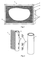
- the condenser 1 shown in Fig. 1 is a part of a refrigerating cycle of a vehicle air condition system, not shown in details on drawings, and is connected between compressor and expansion valve in a manner known to a person skilled in the art.
- Condenser is made of aluminium alloy and comprises a cooling core 2 consisting of plurality of parallel tubes and cooling fins, and two cylindrical headers 3 fluidly connected with reciprocal ends of each tube.
- the cylindrical dryer 4 is fluidly connected with the header by means of three connectors 5, lower two of which enable flow of coolant between the condenser header 3 and the dryer tank 4.
- the entire unit is placed in a furnace, where the one-shot brazing process is carried out.
- Fig. 3 shows an axonometric view of the connector according to the first embodiment of the invention.
- the connector 5 has a cylindrical side surface 9 and two cylindrical butting faces 10 and 11 having cylindrical projections 12a and 13a. Curvatures of said butting faces correspond to curvatures of respective side surfaces of the header 3 and the dryer tank 4.
- Fig. 4 shows a cross-section of the portions of both the header 3 and the dryer tank 4 and the connector 5 according to the second embodiment of the present invention prior preliminary assembling.
- This embodiment differs from the one shown in Fig. 1 by presence of a straight through port 15 that enables flow of a coolant. Said port crosses the cylindrical projections 12b and 13b. As shown, the connector 5 diameter "d" is greater than the distance "h" between faces of cylindrical projections.
- Fig. 5 shows an axonometric view of the connector according to the third embodiment of the invention.
- the cylindrical projections 12c and 12c have notches 16 in the form of serration.
- the side surface of the connector is provided with a fixing recess 14 that facilitates preliminary positioning of the connector prior to brazing.
- the connector shown in cross-section in Fig. 6 is a variation of the above embodiment. Likewise to the connector from the Fig. 4 , it has a straight through port 15. Owing to the fact that the external diameter of the notches 16 is greater than the diameters of orifices in respective side walls of the header 3 and the dryer tank 4, while pressing the said header 3 and the dryer tank 4 together, the notches punches the edges of the orifices 6 and 7 and simultaneously bends them inwards thus fixing the connector onside respective orifices of the header and the dryer tank. As shown the brazing agent interlayer 17 fills the space between the connector butting faces and respective side surfaces of the header and the dryer tank.
Landscapes
- Engineering & Computer Science (AREA)
- Physics & Mathematics (AREA)
- Mechanical Engineering (AREA)
- Thermal Sciences (AREA)
- General Engineering & Computer Science (AREA)
- Air-Conditioning For Vehicles (AREA)
- Vaporization, Distillation, Condensation, Sublimation, And Cold Traps (AREA)
- Drying Of Solid Materials (AREA)
Claims (4)
- Trockner-integrierter Kondensator bzw. Verflüssiger eines Kühlsystems, insbesondere eines Klimaanlagensystems eines Fahrzeugs, wobei der Kondensator einen Kühlungskem aufweist, der aus einer Vielzahl von parallelen Rohren und Kühlrippen besteht, zwei Verteiler, die mit reziproken Enden jedes Rohres Fluidmäßig verbunden sind, und einen zylinderförmigen Trockner-Tank, der Fluidmäßig verbunden ist mit einem Verteiler mittels zumindest zwei Verbinder, die eine geringere Wärmekapazität haben als der Verteiler und der Trockner-Tank, dadurch gekennzeichnet, dass jeder Verbinder (5) ein gleichförmiges zylinderförmiges Element mit einer Seitenfläche (9) ist, wobei eine zylinderförmige konkave Anstoßfläche (10) der Seitenfläche des Verteilers (3) entspricht und einen im Wesentlichen zylinderförmigen Vorsprung (12) hat, und eine zylinderförmige konkave Anstoßfläche (11) der Seitenfläche des Trockner-Tanks (4) entspricht und einen im Wesentlichen zylinderförmigen Vorsprung (13) hat, wobei der Durchmesser (d) des Verbinders (5) größer ist als ein Abstand (h) zwischen den Flächen der zylinderförmigen Vorsprünge, die in Öffnungen (6, 7) des Verteilers (3) und des Trockner-Tanks (4) positioniert sind, und wobei der Verbinder (5) mit dem Verteiler (3) und dem Trockner-Tank (4) mittels eines Lötmittels (17) verbunden ist, das den Raum zwischen den Anstoßflächen (10, 11) des Verbinders und jeweiligen Seitenflächen des Verteilers (3) und des Trockner-Tanks (4) füllt.
- Kondensator bzw. Verflüssiger gemäß Anspruch 1, dadurch gekennzeichnet, dass der Verbinder (5) eine gerade durchgehende Öffnung (15) hat, die die zylinderförmigen Vorsprünge (12b, 12d und 13b, 13d) durchquert.
- Kondensator bzw. Verflüssiger gemäß Anspruch 1 oder 2, dadurch gekennzeichnet, dass die zylinderförmige Seitenfläche (9) des Verbinders (5) zumindest eine Positionierungsaussparung (14) hat.
- Kondensator bzw. Verflüssiger gemäß Anspruch 1, 2 oder 3, dadurch gekennzeichnet, dass die zylinderförmigen Vorsprünge (12c, 12d und 13c, 13d) auf ihren Seitenflächen Einbuchtungen (16) haben, deren äußerer Durchmesser größer ist als ein Durchmesser von entsprechenden Öffnungen (6, 7) in dem Verteiler (3) und dem Trockner-Tank (4).
Priority Applications (4)
| Application Number | Priority Date | Filing Date | Title |
|---|---|---|---|
| EP04460007A EP1584875B1 (de) | 2004-04-08 | 2004-04-08 | Verflüssiger mit integriertem Trocknersammler und Verfahren zu dessen Herstellung |
| AT04460007T ATE463706T1 (de) | 2004-04-08 | 2004-04-08 | Verflüssiger mit integriertem trocknersammler und verfahren zu dessen herstellung |
| DE602004026402T DE602004026402D1 (de) | 2004-04-08 | 2004-04-08 | Verflüssiger mit integriertem Trocknersammler und Verfahren zu dessen Herstellung |
| US11/082,303 US7131293B2 (en) | 2004-04-08 | 2005-03-17 | Dryer integrated condenser of a refrigerating system and a method of assembling the same |
Applications Claiming Priority (1)
| Application Number | Priority Date | Filing Date | Title |
|---|---|---|---|
| EP04460007A EP1584875B1 (de) | 2004-04-08 | 2004-04-08 | Verflüssiger mit integriertem Trocknersammler und Verfahren zu dessen Herstellung |
Publications (2)
| Publication Number | Publication Date |
|---|---|
| EP1584875A1 EP1584875A1 (de) | 2005-10-12 |
| EP1584875B1 true EP1584875B1 (de) | 2010-04-07 |
Family
ID=34896205
Family Applications (1)
| Application Number | Title | Priority Date | Filing Date |
|---|---|---|---|
| EP04460007A Expired - Lifetime EP1584875B1 (de) | 2004-04-08 | 2004-04-08 | Verflüssiger mit integriertem Trocknersammler und Verfahren zu dessen Herstellung |
Country Status (4)
| Country | Link |
|---|---|
| US (1) | US7131293B2 (de) |
| EP (1) | EP1584875B1 (de) |
| AT (1) | ATE463706T1 (de) |
| DE (1) | DE602004026402D1 (de) |
Families Citing this family (14)
| Publication number | Priority date | Publication date | Assignee | Title |
|---|---|---|---|---|
| FR2875897A1 (fr) * | 2004-09-28 | 2006-03-31 | Valeo Thermique Moteur Sas | Echangeur de chaleur comportant au moins une bride pour un collecteur de cet echangeur |
| US20060123837A1 (en) * | 2004-12-10 | 2006-06-15 | Subros Limited | Receiver tank for a condensor and method of manufacturing the same |
| JP4726692B2 (ja) * | 2006-04-26 | 2011-07-20 | サンデン株式会社 | 受液器付き冷媒凝縮器 |
| KR101318629B1 (ko) * | 2007-02-20 | 2013-10-16 | 한라비스테온공조 주식회사 | 수액기를 구비한 콘덴서 |
| CN103090695B (zh) * | 2008-12-15 | 2015-08-19 | 康奈可关精株式会社 | 换热器 |
| JP2014145504A (ja) * | 2013-01-28 | 2014-08-14 | T Rad Co Ltd | 凝縮器 |
| KR101453507B1 (ko) | 2013-02-26 | 2014-10-23 | 이용재 | 자동차 응축기의 드라이어 탱크 연결을 위한 커넥터 |
| US9702358B2 (en) * | 2013-03-15 | 2017-07-11 | Ingersoll-Rand Company | Temperature control for compressor |
| DE102014002407B4 (de) * | 2014-02-20 | 2017-12-21 | Modine Manufacturing Company | Gelöteter Wärmetauscher |
| CN104329159B (zh) * | 2014-07-25 | 2017-04-05 | 李政 | 圆管气室汽车中冷器 |
| CN108895729B (zh) * | 2018-08-13 | 2024-08-02 | 浙江新昌同一汽车部件有限公司 | 一种汽车冷凝器与储液罐的连接结构 |
| US20220065560A1 (en) * | 2018-09-14 | 2022-03-03 | Sanhua (Hangzhou) Micro Channel Heat Exchanger Co., Ltd. | Welding method of connector and connection tube, connection structure and heat exchanger |
| KR102729482B1 (ko) * | 2019-08-27 | 2024-11-14 | 한온시스템 주식회사 | 수랭식 응축기 |
| CN113932500A (zh) * | 2021-11-22 | 2022-01-14 | 上海爱斯达克汽车空调系统有限公司 | 冷凝器储液干燥器及其制造方法 |
Family Cites Families (12)
| Publication number | Priority date | Publication date | Assignee | Title |
|---|---|---|---|---|
| JPH09153172A (ja) | 1995-11-30 | 1997-06-10 | Mitsubishi Heavy Ind Ltd | 自動販売装置 |
| JP3406137B2 (ja) * | 1995-12-06 | 2003-05-12 | カルソニックカンセイ株式会社 | 熱交換器の継手部 |
| JPH102692A (ja) * | 1996-06-14 | 1998-01-06 | Zexel Corp | 熱交換器のブラケット構造 |
| JPH10122705A (ja) | 1996-10-14 | 1998-05-15 | Calsonic Corp | リキッドタンク付コンデンサ |
| JPH10288425A (ja) * | 1997-04-11 | 1998-10-27 | Zexel Corp | レシーバタンクのタンク筐体 |
| US5934102A (en) * | 1998-02-06 | 1999-08-10 | Modine Manufacturing Company | Integral receiver/condenser for a refrigerant |
| US6065534A (en) * | 1998-05-19 | 2000-05-23 | Reynolds Metals Company | Aluminum alloy article and method of use |
| JP2000039232A (ja) * | 1998-07-23 | 2000-02-08 | Sanden Corp | 受液器組込凝縮器 |
| JP2000257992A (ja) * | 1999-03-03 | 2000-09-22 | Nippon Light Metal Co Ltd | 受液器の連結構造 |
| JP4041634B2 (ja) * | 1999-03-30 | 2008-01-30 | カルソニックカンセイ株式会社 | 凝縮器 |
| US6793121B2 (en) * | 2002-03-12 | 2004-09-21 | Newfield Technology Corporation | Clasp having a flange to couple a heat exchanger to a device in a cooling system |
| KR100730567B1 (ko) * | 2002-07-09 | 2007-06-20 | 한라공조주식회사 | 공조장치용 리시버 드라이어 및 그 제작방법 |
-
2004
- 2004-04-08 AT AT04460007T patent/ATE463706T1/de not_active IP Right Cessation
- 2004-04-08 DE DE602004026402T patent/DE602004026402D1/de not_active Expired - Lifetime
- 2004-04-08 EP EP04460007A patent/EP1584875B1/de not_active Expired - Lifetime
-
2005
- 2005-03-17 US US11/082,303 patent/US7131293B2/en not_active Expired - Lifetime
Also Published As
| Publication number | Publication date |
|---|---|
| DE602004026402D1 (de) | 2010-05-20 |
| EP1584875A1 (de) | 2005-10-12 |
| ATE463706T1 (de) | 2010-04-15 |
| US20050223736A1 (en) | 2005-10-13 |
| US7131293B2 (en) | 2006-11-07 |
Similar Documents
| Publication | Publication Date | Title |
|---|---|---|
| US7131293B2 (en) | Dryer integrated condenser of a refrigerating system and a method of assembling the same | |
| JP5351386B2 (ja) | 熱交換器の配管コネクタ | |
| CN101629769A (zh) | 非圆柱形致冷剂导管及其制造方法 | |
| US6216777B1 (en) | Manifold for a heat exchanger and method of making same | |
| JP2000154993A (ja) | 熱交換器 | |
| KR20120044849A (ko) | 헤더유닛 및 이를 가지는 열교환기 | |
| JP2013029243A (ja) | 熱交換器 | |
| US10386125B2 (en) | Heat exchanger having fitting assembly | |
| JPH09126685A (ja) | 熱交換器 | |
| JPH10160382A (ja) | 空調用熱交換器およびその製造方法 | |
| US20020108742A1 (en) | Heat exchanger with cut tubes | |
| JP4782520B2 (ja) | コンデンサのコネクタ固定構造 | |
| CN103582797A (zh) | 热交换器 | |
| CN104180705A (zh) | 转接头及具有该转接头的换热器 | |
| KR101527191B1 (ko) | 열교환기의 제조방법 | |
| KR20080027552A (ko) | 자동차용 열교환기 및 그의 제조방법 | |
| JP2831578B2 (ja) | ブラケットを備えた熱交換器の製造方法 | |
| JP7485993B1 (ja) | 熱交換器 | |
| JP2000046489A (ja) | 積層型熱交換器 | |
| JP2000130986A (ja) | 複式熱交換器 | |
| JP3791079B2 (ja) | 複式熱交換器 | |
| EP1589300A1 (de) | Verbinder für ein rohrförmiges Element, insbesondere Verbinder für Verflüssiger mit integriertem Sammler-Trockner für Kühlkreisläufe | |
| JP4371417B2 (ja) | 熱交換器の製造方法 | |
| KR20000032408A (ko) | 열교환기 | |
| JP2756106B2 (ja) | 熱交換器 |
Legal Events
| Date | Code | Title | Description |
|---|---|---|---|
| PUAI | Public reference made under article 153(3) epc to a published international application that has entered the european phase |
Free format text: ORIGINAL CODE: 0009012 |
|
| AK | Designated contracting states |
Kind code of ref document: A1 Designated state(s): AT BE BG CH CY CZ DE DK EE ES FI FR GB GR HU IE IT LI LU MC NL PL PT RO SE SI SK TR |
|
| AX | Request for extension of the european patent |
Extension state: AL HR LT LV MK |
|
| 17P | Request for examination filed |
Effective date: 20060412 |
|
| AKX | Designation fees paid |
Designated state(s): AT BE BG CH CY CZ DE DK EE ES FI FR GB GR HU IE IT LI LU MC NL PL PT RO SE SI SK TR |
|
| 17Q | First examination report despatched |
Effective date: 20081117 |
|
| GRAP | Despatch of communication of intention to grant a patent |
Free format text: ORIGINAL CODE: EPIDOSNIGR1 |
|
| GRAS | Grant fee paid |
Free format text: ORIGINAL CODE: EPIDOSNIGR3 |
|
| GRAA | (expected) grant |
Free format text: ORIGINAL CODE: 0009210 |
|
| AK | Designated contracting states |
Kind code of ref document: B1 Designated state(s): AT BE BG CH CY CZ DE DK EE ES FI FR GB GR HU IE IT LI LU MC NL PL PT RO SE SI SK TR |
|
| REG | Reference to a national code |
Ref country code: GB Ref legal event code: FG4D |
|
| REG | Reference to a national code |
Ref country code: CH Ref legal event code: EP |
|
| REG | Reference to a national code |
Ref country code: IE Ref legal event code: FG4D |
|
| REF | Corresponds to: |
Ref document number: 602004026402 Country of ref document: DE Date of ref document: 20100520 Kind code of ref document: P |
|
| REG | Reference to a national code |
Ref country code: NL Ref legal event code: VDEP Effective date: 20100407 |
|
| PG25 | Lapsed in a contracting state [announced via postgrant information from national office to epo] |
Ref country code: SI Free format text: LAPSE BECAUSE OF FAILURE TO SUBMIT A TRANSLATION OF THE DESCRIPTION OR TO PAY THE FEE WITHIN THE PRESCRIBED TIME-LIMIT Effective date: 20100407 |
|
| PG25 | Lapsed in a contracting state [announced via postgrant information from national office to epo] |
Ref country code: NL Free format text: LAPSE BECAUSE OF FAILURE TO SUBMIT A TRANSLATION OF THE DESCRIPTION OR TO PAY THE FEE WITHIN THE PRESCRIBED TIME-LIMIT Effective date: 20100407 Ref country code: ES Free format text: LAPSE BECAUSE OF FAILURE TO SUBMIT A TRANSLATION OF THE DESCRIPTION OR TO PAY THE FEE WITHIN THE PRESCRIBED TIME-LIMIT Effective date: 20100718 Ref country code: SE Free format text: LAPSE BECAUSE OF FAILURE TO SUBMIT A TRANSLATION OF THE DESCRIPTION OR TO PAY THE FEE WITHIN THE PRESCRIBED TIME-LIMIT Effective date: 20100407 |
|
| PG25 | Lapsed in a contracting state [announced via postgrant information from national office to epo] |
Ref country code: AT Free format text: LAPSE BECAUSE OF FAILURE TO SUBMIT A TRANSLATION OF THE DESCRIPTION OR TO PAY THE FEE WITHIN THE PRESCRIBED TIME-LIMIT Effective date: 20100407 Ref country code: FI Free format text: LAPSE BECAUSE OF FAILURE TO SUBMIT A TRANSLATION OF THE DESCRIPTION OR TO PAY THE FEE WITHIN THE PRESCRIBED TIME-LIMIT Effective date: 20100407 Ref country code: MC Free format text: LAPSE BECAUSE OF NON-PAYMENT OF DUE FEES Effective date: 20100430 |
|
| REG | Reference to a national code |
Ref country code: CH Ref legal event code: PL |
|
| PG25 | Lapsed in a contracting state [announced via postgrant information from national office to epo] |
Ref country code: GR Free format text: LAPSE BECAUSE OF FAILURE TO SUBMIT A TRANSLATION OF THE DESCRIPTION OR TO PAY THE FEE WITHIN THE PRESCRIBED TIME-LIMIT Effective date: 20100708 Ref country code: CY Free format text: LAPSE BECAUSE OF FAILURE TO SUBMIT A TRANSLATION OF THE DESCRIPTION OR TO PAY THE FEE WITHIN THE PRESCRIBED TIME-LIMIT Effective date: 20100421 Ref country code: PL Free format text: LAPSE BECAUSE OF FAILURE TO SUBMIT A TRANSLATION OF THE DESCRIPTION OR TO PAY THE FEE WITHIN THE PRESCRIBED TIME-LIMIT Effective date: 20100407 |
|
| PG25 | Lapsed in a contracting state [announced via postgrant information from national office to epo] |
Ref country code: EE Free format text: LAPSE BECAUSE OF FAILURE TO SUBMIT A TRANSLATION OF THE DESCRIPTION OR TO PAY THE FEE WITHIN THE PRESCRIBED TIME-LIMIT Effective date: 20100407 Ref country code: DK Free format text: LAPSE BECAUSE OF FAILURE TO SUBMIT A TRANSLATION OF THE DESCRIPTION OR TO PAY THE FEE WITHIN THE PRESCRIBED TIME-LIMIT Effective date: 20100407 Ref country code: PT Free format text: LAPSE BECAUSE OF FAILURE TO SUBMIT A TRANSLATION OF THE DESCRIPTION OR TO PAY THE FEE WITHIN THE PRESCRIBED TIME-LIMIT Effective date: 20100809 Ref country code: IE Free format text: LAPSE BECAUSE OF NON-PAYMENT OF DUE FEES Effective date: 20100408 |
|
| PLBE | No opposition filed within time limit |
Free format text: ORIGINAL CODE: 0009261 |
|
| STAA | Information on the status of an ep patent application or granted ep patent |
Free format text: STATUS: NO OPPOSITION FILED WITHIN TIME LIMIT |
|
| PG25 | Lapsed in a contracting state [announced via postgrant information from national office to epo] |
Ref country code: LI Free format text: LAPSE BECAUSE OF NON-PAYMENT OF DUE FEES Effective date: 20100430 Ref country code: RO Free format text: LAPSE BECAUSE OF FAILURE TO SUBMIT A TRANSLATION OF THE DESCRIPTION OR TO PAY THE FEE WITHIN THE PRESCRIBED TIME-LIMIT Effective date: 20100407 Ref country code: CZ Free format text: LAPSE BECAUSE OF FAILURE TO SUBMIT A TRANSLATION OF THE DESCRIPTION OR TO PAY THE FEE WITHIN THE PRESCRIBED TIME-LIMIT Effective date: 20100407 Ref country code: BE Free format text: LAPSE BECAUSE OF FAILURE TO SUBMIT A TRANSLATION OF THE DESCRIPTION OR TO PAY THE FEE WITHIN THE PRESCRIBED TIME-LIMIT Effective date: 20100407 Ref country code: SK Free format text: LAPSE BECAUSE OF FAILURE TO SUBMIT A TRANSLATION OF THE DESCRIPTION OR TO PAY THE FEE WITHIN THE PRESCRIBED TIME-LIMIT Effective date: 20100407 Ref country code: CH Free format text: LAPSE BECAUSE OF NON-PAYMENT OF DUE FEES Effective date: 20100430 |
|
| 26N | No opposition filed |
Effective date: 20110110 |
|
| GBPC | Gb: european patent ceased through non-payment of renewal fee |
Effective date: 20100707 |
|
| PG25 | Lapsed in a contracting state [announced via postgrant information from national office to epo] |
Ref country code: GB Free format text: LAPSE BECAUSE OF NON-PAYMENT OF DUE FEES Effective date: 20100707 |
|
| PG25 | Lapsed in a contracting state [announced via postgrant information from national office to epo] |
Ref country code: LU Free format text: LAPSE BECAUSE OF NON-PAYMENT OF DUE FEES Effective date: 20100408 Ref country code: HU Free format text: LAPSE BECAUSE OF FAILURE TO SUBMIT A TRANSLATION OF THE DESCRIPTION OR TO PAY THE FEE WITHIN THE PRESCRIBED TIME-LIMIT Effective date: 20101008 Ref country code: BG Free format text: LAPSE BECAUSE OF FAILURE TO SUBMIT A TRANSLATION OF THE DESCRIPTION OR TO PAY THE FEE WITHIN THE PRESCRIBED TIME-LIMIT Effective date: 20100407 |
|
| PG25 | Lapsed in a contracting state [announced via postgrant information from national office to epo] |
Ref country code: TR Free format text: LAPSE BECAUSE OF FAILURE TO SUBMIT A TRANSLATION OF THE DESCRIPTION OR TO PAY THE FEE WITHIN THE PRESCRIBED TIME-LIMIT Effective date: 20100407 |
|
| PG25 | Lapsed in a contracting state [announced via postgrant information from national office to epo] |
Ref country code: BG Free format text: LAPSE BECAUSE OF FAILURE TO SUBMIT A TRANSLATION OF THE DESCRIPTION OR TO PAY THE FEE WITHIN THE PRESCRIBED TIME-LIMIT Effective date: 20100707 |
|
| REG | Reference to a national code |
Ref country code: DE Ref legal event code: R082 Ref document number: 602004026402 Country of ref document: DE Representative=s name: BRP RENAUD UND PARTNER MBB RECHTSANWAELTE PATE, DE Ref country code: DE Ref legal event code: R082 Ref document number: 602004026402 Country of ref document: DE Representative=s name: BRP RENAUD UND PARTNER MBB, DE Ref country code: DE Ref legal event code: R081 Ref document number: 602004026402 Country of ref document: DE Owner name: MAHLE INTERNATIONAL GMBH, DE Free format text: FORMER OWNER: DELPHI TECHNOLOGIES, INC., TROY, MICH., US |
|
| REG | Reference to a national code |
Ref country code: FR Ref legal event code: PLFP Year of fee payment: 13 |
|
| REG | Reference to a national code |
Ref country code: FR Ref legal event code: PLFP Year of fee payment: 14 |
|
| REG | Reference to a national code |
Ref country code: FR Ref legal event code: TP Owner name: MAHLE INTERNATIONAL GMBH, DE Effective date: 20180103 |
|
| REG | Reference to a national code |
Ref country code: FR Ref legal event code: PLFP Year of fee payment: 15 |
|
| PGFP | Annual fee paid to national office [announced via postgrant information from national office to epo] |
Ref country code: IT Payment date: 20180420 Year of fee payment: 15 Ref country code: FR Payment date: 20180502 Year of fee payment: 15 |
|
| PG25 | Lapsed in a contracting state [announced via postgrant information from national office to epo] |
Ref country code: IT Free format text: LAPSE BECAUSE OF NON-PAYMENT OF DUE FEES Effective date: 20190408 |
|
| PG25 | Lapsed in a contracting state [announced via postgrant information from national office to epo] |
Ref country code: FR Free format text: LAPSE BECAUSE OF NON-PAYMENT OF DUE FEES Effective date: 20190430 |
|
| PGFP | Annual fee paid to national office [announced via postgrant information from national office to epo] |
Ref country code: DE Payment date: 20230420 Year of fee payment: 20 |
|
| REG | Reference to a national code |
Ref country code: DE Ref legal event code: R071 Ref document number: 602004026402 Country of ref document: DE |