EP1586740A2 - Rotor intégral (Blisk) de turbine - Google Patents
Rotor intégral (Blisk) de turbine Download PDFInfo
- Publication number
- EP1586740A2 EP1586740A2 EP05252172A EP05252172A EP1586740A2 EP 1586740 A2 EP1586740 A2 EP 1586740A2 EP 05252172 A EP05252172 A EP 05252172A EP 05252172 A EP05252172 A EP 05252172A EP 1586740 A2 EP1586740 A2 EP 1586740A2
- Authority
- EP
- European Patent Office
- Prior art keywords
- blades
- blade
- blisk
- disc
- periphery
- Prior art date
- Legal status (The legal status is an assumption and is not a legal conclusion. Google has not performed a legal analysis and makes no representation as to the accuracy of the status listed.)
- Withdrawn
Links
Images
Classifications
-
- F—MECHANICAL ENGINEERING; LIGHTING; HEATING; WEAPONS; BLASTING
- F01—MACHINES OR ENGINES IN GENERAL; ENGINE PLANTS IN GENERAL; STEAM ENGINES
- F01D—NON-POSITIVE DISPLACEMENT MACHINES OR ENGINES, e.g. STEAM TURBINES
- F01D5/00—Blades; Blade-carrying members; Heating, heat-insulating, cooling or antivibration means on the blades or the members
- F01D5/02—Blade-carrying members, e.g. rotors
- F01D5/08—Heating, heat-insulating or cooling means
- F01D5/081—Cooling fluid being directed on the side of the rotor disc or at the roots of the blades
-
- B—PERFORMING OPERATIONS; TRANSPORTING
- B22—CASTING; POWDER METALLURGY
- B22F—WORKING METALLIC POWDER; MANUFACTURE OF ARTICLES FROM METALLIC POWDER; MAKING METALLIC POWDER; APPARATUS OR DEVICES SPECIALLY ADAPTED FOR METALLIC POWDER
- B22F3/00—Manufacture of workpieces or articles from metallic powder characterised by the manner of compacting or sintering; Apparatus specially adapted therefor ; Presses and furnaces
- B22F3/12—Both compacting and sintering
- B22F3/14—Both compacting and sintering simultaneously
- B22F3/15—Hot isostatic pressing
-
- B—PERFORMING OPERATIONS; TRANSPORTING
- B22—CASTING; POWDER METALLURGY
- B22F—WORKING METALLIC POWDER; MANUFACTURE OF ARTICLES FROM METALLIC POWDER; MAKING METALLIC POWDER; APPARATUS OR DEVICES SPECIALLY ADAPTED FOR METALLIC POWDER
- B22F5/00—Manufacture of workpieces or articles from metallic powder characterised by the special shape of the product
- B22F5/009—Manufacture of workpieces or articles from metallic powder characterised by the special shape of the product of turbine components other than turbine blades
-
- B—PERFORMING OPERATIONS; TRANSPORTING
- B22—CASTING; POWDER METALLURGY
- B22F—WORKING METALLIC POWDER; MANUFACTURE OF ARTICLES FROM METALLIC POWDER; MAKING METALLIC POWDER; APPARATUS OR DEVICES SPECIALLY ADAPTED FOR METALLIC POWDER
- B22F7/00—Manufacture of composite layers, workpieces, or articles, comprising metallic powder, by sintering the powder, with or without compacting wherein at least one part is obtained by sintering or compression
- B22F7/06—Manufacture of composite layers, workpieces, or articles, comprising metallic powder, by sintering the powder, with or without compacting wherein at least one part is obtained by sintering or compression of composite workpieces or articles from parts, e.g. to form tipped tools
- B22F7/08—Manufacture of composite layers, workpieces, or articles, comprising metallic powder, by sintering the powder, with or without compacting wherein at least one part is obtained by sintering or compression of composite workpieces or articles from parts, e.g. to form tipped tools with one or more parts not made from powder
-
- F—MECHANICAL ENGINEERING; LIGHTING; HEATING; WEAPONS; BLASTING
- F01—MACHINES OR ENGINES IN GENERAL; ENGINE PLANTS IN GENERAL; STEAM ENGINES
- F01D—NON-POSITIVE DISPLACEMENT MACHINES OR ENGINES, e.g. STEAM TURBINES
- F01D5/00—Blades; Blade-carrying members; Heating, heat-insulating, cooling or antivibration means on the blades or the members
- F01D5/12—Blades
- F01D5/14—Form or construction
- F01D5/18—Hollow blades, i.e. blades with cooling or heating channels or cavities; Heating, heat-insulating or cooling means on blades
- F01D5/187—Convection cooling
-
- F—MECHANICAL ENGINEERING; LIGHTING; HEATING; WEAPONS; BLASTING
- F01—MACHINES OR ENGINES IN GENERAL; ENGINE PLANTS IN GENERAL; STEAM ENGINES
- F01D—NON-POSITIVE DISPLACEMENT MACHINES OR ENGINES, e.g. STEAM TURBINES
- F01D5/00—Blades; Blade-carrying members; Heating, heat-insulating, cooling or antivibration means on the blades or the members
- F01D5/30—Fixing blades to rotors; Blade roots ; Blade spacers
- F01D5/3061—Fixing blades to rotors; Blade roots ; Blade spacers by welding, brazing
Definitions
- the invention relates to a turbine blisk.
- it concerns the manner in which a turbine blisk may be manufactured.
- blisk is a contraction of the two words "bladed disk” and is used in the field of gas turbine engines to refer to a unified assembly of a turbine disk together with a circumferential array of turbine blades. It may be used in the case either where the whole assembly has been machined from a single piece of metal or where the supporting disc and the blades have been irreversibly joined, for example by welding. "Single piece of metal” shall be taken for present purposes to include a metal article, such as the turbine disc, made from metal powder, which has been joined into a whole by a hot isostatic bonding process.
- the present invention seeks to overcome the above mentioned drawbacks by utilising the root section of individually cast blades instead of the platform to form a hoop continuous ring, which thereby forms the head of the disc, shielding the remainder of the disc.
- a blisk comprising a disc having a periphery, a plurality of blades spaced apart around the periphery of the disc, each of said blades consisting of shank and an airfoil section which extends outwardly from the periphery of the disc in a generally radial direction, each airfoil blade section is formed with internal cooling passages which communicate with at least one orifice in the blade shank and has a circumferentially extending platform lying between the shank and the airfoil blade section, wherein the platforms extend towards each other in a circumferential direction and confronting edges of neighbouring blades are sealed one to another to form a substantially continuous ring spaced a radial distance above the periphery of the disc such that between each pair of neighbouring shanks there is defined a plenum chamber containing the blades shanks, with which the internal cooling passages of the blades communicate.
- each of said blades further consists of a root section wherein the dimensions of the roots in the in the direction of the disc circumference are such that neighbouring roots abut to form a continuous ring defining the periphery of the disc.
- a method of manufacturing the blisk comprises the steps of forming a plurality of blades, each blade having a root the dimensions of which are such when the blades are disposed in a circular array the roots of each blade abuts its neighbours, disposing the blades in such a circular array and joining adjacent blades to form a continuous ring defining the periphery of the disc.
- a single rotary stage of an axial flow compressor in the form of a Blisk 2.
- the defining characteristic of a Blisk a contraction of the words Bladed disk, is that the rotor disk 4 and the whole set of rotor blades 6 are either formed integrally, for example by machining from solid, or are formed separately and then permanently joined together, for example by welding.
- the blades are cast or forged, with an airfoil section upstanding from a platform and below the platform a shank and a root section.
- the edges of the platforms are profiled to abut opposite edges of neighbouring platforms when the blades are assembled onto the periphery of the rotor disk.
- the roots are shaped to engage axially extending dovetail slots in the rim of the disk.
- Another method of mounting blades comprises a circumferentially extending profiled slot in the disk rim; the blade roots are complementarily shaped and are inserted through a keyhole and slid around the slot until the platforms abut. The slot profile and root shape retain the blades in position.
- the cooling air path Before entering the blade roots the cooling air path may be arranged to draw the air across the face of the rotor disk thereby cooling it. Also when the blades are assembled in a ring the blade platforms form a complete annulus shielding the disc head from the temperature of the main gas path. This has the advantage of permitting the disc rim to be spaced from the blade platforms, and the passage of cooling air across the face of the disc provides convection cooling for the disc head, thereby reducing its operating temperature and optimising its mechanical properties.
- Blisks may be cast as a single unit or machined from solid, with the airfoil sections of the blades upstanding from the rim of the disk. This kind of arrangement effectively precludes internal cooling of the blades so the head of the disk is subject to operating temperatures closer to the main gas path temperatures. As a result of the higher operating temperature the mechanical strength of the Blisk is reduced
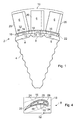
- a blisk 2 comprises a disc 4 around the circumference of which is disposed a plurality of blades 6 in an annular array.
- the blades 6 are formed separately from the disc 4, preferably by casting, although other methods are not excluded. It follows also that the disk 4 and blades 6 are not necessarily manufactured of identical materials, of which more below.
- the blades 6 are then joined one to another in an annular array. It is preferred to cast the blades individually and to subsequently join them together. However, it is to be understood that it is intended that the invention shall also include blades cast in groups comprising more than one.
- Each blade 6 is formed with the dimensions of its root 8 in the direction of the circumference of disk 4 such that the roots 8 of adjacent blades 6 abut.
- abutting roots are joined to form a continuous ring defining the periphery of the disc 4.
- Part of this ring of blades is indicated at 10 in Figure 1.
- the roots 8 of blades 6 are joined permanently by welding but in other examples other methods of joining such as brazing may be employed.
- the roots 8 have a constant radial depth over most of their circumferential length, except at the edges 14 which abut the root 8 of a neighbouring blade.
- the edges 14 are chamfered, or tapered, to a depth at which the margins of the roots may be easily welded together.
- the depth of these edges 14 is such that the joint region may be penetrated at a single weld pass from one side, without generating sufficient heat to cause distortion of the roots 8 at the weld margins.
- a short depth is also desirable to help to ensure the joints are easily and successfully brazed.
- the roots 8 of the blades 6 project radially inwardly towards the centre of the disk 4, which is also the centre of the blade ring 10.
- the roots 8 occupy part of the volume of the rotor disk 4, and when joined in the blade ring present an inward facing profile of depth, which varies around the annulus due to the chamfered edges 14 of the blade roots 8.
- the remaining volume space of disk 4 is filled with metal powder, the spaces between the chamfered edges 14 is also filled.
- HIPping die parts When the space between HIPping die parts is filled the whole is consolidated into a single mass by a hot isostatic pressing (HIP) process.
- HIP hot isostatic pressing
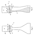
- each blade 6 has a shank 16 that extends outwardly from the root 8 and carries a blade platform 18 upon which is mounted the airfoil blade section 20.
- the dimensions of the blade platforms 18 in the direction of the disk circumference are such that the platforms 18 form a substantially continuous ring spaced a radial distance above the periphery of the disk. 4 This defines an annular plenum chamber 22 encircling the disk 4 and containing the blades shanks 16.
- the dimensions of the blade platforms 18 in the circumferential direction may be sufficient that adjacent platform edges abut one another in which case they may be joined permanently such as by welding or brazing as previously described.
- adjacent platform edges may be sealed using, for example, seal strips of the kind used to seal gaps between guide vanes assemblies.
- the faces of each pair of confronting platform edges are formed with longitudinally extending slots into which is fitted an elongate metal strip. Although the strip is trapped in the slots it is free to move a small amount so that when, in operation, there is a pressure difference across the gap the strip is urged against the edges of the slots to seal the gap.
- the airfoil section 20 of each of the blades 6 is formed with internal cooling passages 24,26,28 that communicate with the plenum chamber 22 through at least one orifice formed in the blade shank 16.
- three such cooling entry orifices 30, 32, 34 are shown leading into the passages 24, 26, 28 respectively.
- the arrangement illustrated is indicative only and is not intended to represent a working arrangement, for example cooling exit holes are not depicted. Suitable practical arrangements will be familiar to those skilled in the art of turbine blade cooling.
- a preferred method of manufacturing a blisk of the kind described above comprises the steps of forming a plurality of blades 6, which may be cast with internal cooling passages.
- the blades are each cast with a root 8 the dimensions of which are such when the blades 6 are disposed in a circular array the roots of each blade abuts its neighbours.
- the blades are then temporarily clamped in a circular array, and adjacent blades are welded together to form a continuous ring 10.
- this blade ring defines the periphery of the rotor disk.
- the ring is then located between hollow die parts defining the two opposite side faces of the rotor disk.
- the rotor disk is formed by a HIPping process, in which the closed volume is filled with metal powder, and the blade roots and powder disk are consolidated into an integral mass by a hot isostatic pressing process.
- the materials used for these parts need not be the same; so for example the blades 6, including the blade roots 8, may be cast from a nickel alloy known as MAR-M-002 preferred for turbine applications, while a nickel alloy powder known as UDIMET 720 is used to form the HIPped disk 4.
- blade platforms 18 are spaced a short distance above the rim of disk 4 and a portion of the blade shank 16, that is the part lying between the blade root 8 and the blade platform 18, protrudes above the rim of the rotor disk. There is thus created the annular plenum space 22 under the ring of blade platforms 18.
- this annular space under the blade platforms 18 is utilised as a plenum chamber 22 for collecting cooling air which may then be used to cool the turbine blades 6 through orifices formed in the blade root shank 16 and through internal passages 24, 26, 28 in the aerofoil in known manner.
- the internal cooling passages 24-28 and 30-34 are created by the use of ceramic cores (not shown) which are subsequently leached out leaving the internal passages and cavities.
- cooling air is sourced from the region of the centre axis of the engine along an axial pathway. Cooling air then passes radially outwards over the face of the Blisk rotor and cools the disc head.
Landscapes
- Engineering & Computer Science (AREA)
- Mechanical Engineering (AREA)
- General Engineering & Computer Science (AREA)
- Manufacturing & Machinery (AREA)
- Chemical & Material Sciences (AREA)
- Composite Materials (AREA)
- Materials Engineering (AREA)
- Turbine Rotor Nozzle Sealing (AREA)
- Powder Metallurgy (AREA)
Applications Claiming Priority (2)
| Application Number | Priority Date | Filing Date | Title |
|---|---|---|---|
| GB0408497 | 2004-04-16 | ||
| GBGB0408497.6A GB0408497D0 (en) | 2004-04-16 | 2004-04-16 | Turbine blisk |
Publications (2)
| Publication Number | Publication Date |
|---|---|
| EP1586740A2 true EP1586740A2 (fr) | 2005-10-19 |
| EP1586740A3 EP1586740A3 (fr) | 2014-07-23 |
Family
ID=32320940
Family Applications (1)
| Application Number | Title | Priority Date | Filing Date |
|---|---|---|---|
| EP20050252172 Withdrawn EP1586740A3 (fr) | 2004-04-16 | 2005-04-07 | Rotor intégral (Blisk) de turbine |
Country Status (3)
| Country | Link |
|---|---|
| US (1) | US7431564B2 (fr) |
| EP (1) | EP1586740A3 (fr) |
| GB (1) | GB0408497D0 (fr) |
Cited By (5)
| Publication number | Priority date | Publication date | Assignee | Title |
|---|---|---|---|---|
| EP1978208A3 (fr) * | 2007-03-07 | 2012-12-12 | Honeywell International Inc. | Rotors de turbine multi-alliage et procédés de fabrication des rotors |
| CN104420893A (zh) * | 2013-08-30 | 2015-03-18 | 通用电气公司 | 具有多孔冷却特征的燃气涡轮机部件 |
| CN104625629A (zh) * | 2014-12-23 | 2015-05-20 | 中国航空工业集团公司北京航空制造工程研究所 | 一种钛铝合金整体叶盘及其制备方法 |
| RU2610658C2 (ru) * | 2015-08-05 | 2017-02-14 | Федеральное государственное унитарное предприятие "Всероссийский научно-исследовательский институт авиационных материалов" (ФГУП "ВИАМ") | Способ изготовления составных заготовок типа "диск-диск" и "диск-вал" из жаропрочных титановых и никелевых сплавов |
| EP3926139B1 (fr) * | 2020-06-19 | 2023-06-07 | ITP Engines UK Ltd | Roue de rotor à pales |
Families Citing this family (22)
| Publication number | Priority date | Publication date | Assignee | Title |
|---|---|---|---|---|
| US20100322767A1 (en) * | 2009-06-18 | 2010-12-23 | Nadvit Gregory M | Turbine Blade Having Platform Cooling Holes |
| US20090119919A1 (en) * | 2007-11-12 | 2009-05-14 | Honeywell International, Inc. | Components for gas turbine engines and methods for manufacturing components for gas turbine engines |
| US8469656B1 (en) | 2008-01-15 | 2013-06-25 | Siemens Energy, Inc. | Airfoil seal system for gas turbine engine |
| DE102009007468A1 (de) | 2009-02-04 | 2010-08-19 | Mtu Aero Engines Gmbh | Integral beschaufelte Rotorscheibe für eine Turbine |
| US8187724B2 (en) * | 2009-02-24 | 2012-05-29 | Honeywell International Inc. | Method of manufacture of a dual alloy impeller |
| DE102009052305A1 (de) | 2009-11-07 | 2011-05-12 | Mtu Aero Engines Gmbh | Blisk, Gasturbine und Verfahren zur Herstellung einer derartigen Blisk |
| US8556576B2 (en) * | 2010-09-30 | 2013-10-15 | Florida Turbine Technologies, Inc. | Cooled IBR for a micro-turbine |
| EP2453108B1 (fr) | 2010-11-15 | 2016-04-20 | MTU Aero Engines GmbH | Rotor pour une turbomachine |
| US9022727B2 (en) | 2010-11-15 | 2015-05-05 | Mtu Aero Engines Gmbh | Rotor for a turbo machine |
| US8992168B2 (en) | 2011-10-28 | 2015-03-31 | United Technologies Corporation | Rotating vane seal with cooling air passages |
| US10180067B2 (en) | 2012-05-31 | 2019-01-15 | United Technologies Corporation | Mate face cooling holes for gas turbine engine component |
| WO2014186005A2 (fr) | 2013-02-15 | 2014-11-20 | United Technologies Corporation | Composant de turbine à gaz doté d'une face d'accouplement combinée et d'un refroidissement de plate-forme |
| US9724780B2 (en) | 2014-06-05 | 2017-08-08 | Honeywell International Inc. | Dual alloy turbine rotors and methods for manufacturing the same |
| US20160146016A1 (en) * | 2014-11-24 | 2016-05-26 | General Electric Company | Rotor rim impingement cooling |
| US9903214B2 (en) | 2015-05-26 | 2018-02-27 | General Electric Company | Internally cooled turbine blisk and method of manufacture |
| US10024170B1 (en) * | 2016-06-23 | 2018-07-17 | Florida Turbine Technologies, Inc. | Integrally bladed rotor with bore entry cooling holes |
| US10247015B2 (en) | 2017-01-13 | 2019-04-02 | Rolls-Royce Corporation | Cooled blisk with dual wall blades for gas turbine engine |
| US10934865B2 (en) | 2017-01-13 | 2021-03-02 | Rolls-Royce Corporation | Cooled single walled blisk for gas turbine engine |
| US10415403B2 (en) | 2017-01-13 | 2019-09-17 | Rolls-Royce North American Technologies Inc. | Cooled blisk for gas turbine engine |
| US10718218B2 (en) | 2018-03-05 | 2020-07-21 | Rolls-Royce North American Technologies Inc. | Turbine blisk with airfoil and rim cooling |
| US11808166B1 (en) | 2021-08-19 | 2023-11-07 | United States Of America As Represented By The Administrator Of Nasa | Additively manufactured bladed-disk having blades with integral tuned mass absorbers |
| CN114309606B (zh) * | 2021-12-31 | 2023-08-15 | 北京钢研高纳科技股份有限公司 | 一种单叶片与粉末盘双合金整体叶盘及其制备方法 |
Family Cites Families (11)
| Publication number | Priority date | Publication date | Assignee | Title |
|---|---|---|---|---|
| GB1266505A (fr) * | 1968-09-17 | 1972-03-08 | ||
| US3606573A (en) * | 1969-08-15 | 1971-09-20 | Gen Motors Corp | Porous laminate |
| DE2013937A1 (de) * | 1970-03-24 | 1971-10-07 | Motoren Turbinen Union | Schaufel Scheiben Verbindung |
| US4096615A (en) * | 1977-05-31 | 1978-06-27 | General Motors Corporation | Turbine rotor fabrication |
| US4152816A (en) * | 1977-06-06 | 1979-05-08 | General Motors Corporation | Method of manufacturing a hybrid turbine rotor |
| US4270256A (en) * | 1979-06-06 | 1981-06-02 | General Motors Corporation | Manufacture of composite turbine rotors |
| JPS5969479A (ja) | 1982-10-08 | 1984-04-19 | 日産自動車株式会社 | セラミツクスタ−ビンロ−タの製造方法 |
| US4767274A (en) * | 1986-12-29 | 1988-08-30 | United Technologies Corporation | Multiple lug blade to disk attachment |
| US4784573A (en) * | 1987-08-17 | 1988-11-15 | United Technologies Corporation | Turbine blade attachment |
| US5273708A (en) * | 1992-06-23 | 1993-12-28 | Howmet Corporation | Method of making a dual alloy article |
| GB2372784A (en) | 2000-11-24 | 2002-09-04 | Eclectic Energy Ltd | Air Turbine Interlocking Blade Root and Hub Assembly |
-
2004
- 2004-04-16 GB GBGB0408497.6A patent/GB0408497D0/en not_active Ceased
-
2005
- 2005-04-07 EP EP20050252172 patent/EP1586740A3/fr not_active Withdrawn
- 2005-04-08 US US11/101,444 patent/US7431564B2/en not_active Expired - Fee Related
Cited By (6)
| Publication number | Priority date | Publication date | Assignee | Title |
|---|---|---|---|---|
| EP1978208A3 (fr) * | 2007-03-07 | 2012-12-12 | Honeywell International Inc. | Rotors de turbine multi-alliage et procédés de fabrication des rotors |
| EP2653653A1 (fr) * | 2007-03-07 | 2013-10-23 | Honeywell International Inc. | Rotors de turbine multi-alliage et procédés de fabrication des rotors |
| CN104420893A (zh) * | 2013-08-30 | 2015-03-18 | 通用电气公司 | 具有多孔冷却特征的燃气涡轮机部件 |
| CN104625629A (zh) * | 2014-12-23 | 2015-05-20 | 中国航空工业集团公司北京航空制造工程研究所 | 一种钛铝合金整体叶盘及其制备方法 |
| RU2610658C2 (ru) * | 2015-08-05 | 2017-02-14 | Федеральное государственное унитарное предприятие "Всероссийский научно-исследовательский институт авиационных материалов" (ФГУП "ВИАМ") | Способ изготовления составных заготовок типа "диск-диск" и "диск-вал" из жаропрочных титановых и никелевых сплавов |
| EP3926139B1 (fr) * | 2020-06-19 | 2023-06-07 | ITP Engines UK Ltd | Roue de rotor à pales |
Also Published As
| Publication number | Publication date |
|---|---|
| EP1586740A3 (fr) | 2014-07-23 |
| US20050232780A1 (en) | 2005-10-20 |
| US7431564B2 (en) | 2008-10-07 |
| GB0408497D0 (en) | 2004-05-19 |
Similar Documents
| Publication | Publication Date | Title |
|---|---|---|
| US7431564B2 (en) | Turbine blisk | |
| EP2626169B1 (fr) | Procédés et ensembles d'outillages pour la fabrication de composants de moteur de turbine à gaz métallurgiquement consolidés | |
| US5248240A (en) | Turbine stator vane assembly | |
| US5655876A (en) | Low leakage turbine nozzle | |
| US4335997A (en) | Stress resistant hybrid radial turbine wheel | |
| US9726022B2 (en) | Axially-split radial turbines | |
| EP3068975B1 (fr) | Composant de moteur à turbine à gaz et procédés associés de fabrication | |
| US6354797B1 (en) | Brazeless fillet turbine nozzle | |
| US7984547B2 (en) | Method for manufacturing and/or repairing components for gas turbines | |
| EP3058177B1 (fr) | Procédé de formation d'un composant d'un moteur à turbine à gaz | |
| CA2870740C (fr) | Profil aerodynamique de turbine a commande d'epaisseur de paroi locale | |
| US10247015B2 (en) | Cooled blisk with dual wall blades for gas turbine engine | |
| EP2803820B1 (fr) | Rotor intégral de turbine refroidi par impact | |
| US10934865B2 (en) | Cooled single walled blisk for gas turbine engine | |
| US10415403B2 (en) | Cooled blisk for gas turbine engine | |
| EP2586992B1 (fr) | Étanchéité d'une aube tournante comportant des passages d'air de refroidissement | |
| CN106103901B (zh) | 转子叶片或导叶组件 | |
| US8038405B2 (en) | Spring seal for turbine dovetail | |
| US20140130353A1 (en) | Components for gas turbine engines and methods for manufacturing components for gas turbine engines | |
| US10767496B2 (en) | Turbine blade assembly with mounted platform | |
| EP2586971B1 (fr) | Joints d'étanchéité, rotor, axe et procédé d'orientation des flux de force lors de l'assemblage du rotor | |
| EP1657407B1 (fr) | Procédé pour le refroidissement des talons d'aubes mobiles d'une turbine à gaz | |
| EP1609950B1 (fr) | Manchon crénelé pour aube de turbomachine | |
| US10161253B2 (en) | Blade having hollow part span shroud with cooling passages | |
| EP3873695B1 (fr) | Procédé et appareil pour améliorer le refroidissement d'un carénage de turbine |
Legal Events
| Date | Code | Title | Description |
|---|---|---|---|
| PUAI | Public reference made under article 153(3) epc to a published international application that has entered the european phase |
Free format text: ORIGINAL CODE: 0009012 |
|
| AK | Designated contracting states |
Kind code of ref document: A2 Designated state(s): AT BE BG CH CY CZ DE DK EE ES FI FR GB GR HU IE IS IT LI LT LU MC NL PL PT RO SE SI SK TR |
|
| AX | Request for extension of the european patent |
Extension state: AL BA HR LV MK YU |
|
| PUAL | Search report despatched |
Free format text: ORIGINAL CODE: 0009013 |
|
| AK | Designated contracting states |
Kind code of ref document: A3 Designated state(s): AT BE BG CH CY CZ DE DK EE ES FI FR GB GR HU IE IS IT LI LT LU MC NL PL PT RO SE SI SK TR |
|
| AX | Request for extension of the european patent |
Extension state: AL BA HR LV MK YU |
|
| RIC1 | Information provided on ipc code assigned before grant |
Ipc: F01D 5/18 20060101ALI20140618BHEP Ipc: B23P 15/00 20060101ALI20140618BHEP Ipc: F01D 5/30 20060101ALI20140618BHEP Ipc: F01D 5/08 20060101ALI20140618BHEP Ipc: F01D 5/34 20060101AFI20140618BHEP |
|
| 17P | Request for examination filed |
Effective date: 20140728 |
|
| RBV | Designated contracting states (corrected) |
Designated state(s): AT BE BG CH CY CZ DE DK EE ES FI FR GB GR HU IE IS IT LI LT LU MC NL PL PT RO SE SI SK TR |
|
| AKX | Designation fees paid |
Designated state(s): DE FR GB |
|
| AXX | Extension fees paid |
Extension state: LV Extension state: BA Extension state: YU Extension state: MK Extension state: AL Extension state: HR |
|
| 17Q | First examination report despatched |
Effective date: 20150421 |
|
| RAP1 | Party data changed (applicant data changed or rights of an application transferred) |
Owner name: ROLLS-ROYCE PLC |
|
| STAA | Information on the status of an ep patent application or granted ep patent |
Free format text: STATUS: THE APPLICATION IS DEEMED TO BE WITHDRAWN |
|
| 18D | Application deemed to be withdrawn |
Effective date: 20150902 |