EP3058177B1 - Procédé de formation d'un composant d'un moteur à turbine à gaz - Google Patents
Procédé de formation d'un composant d'un moteur à turbine à gaz Download PDFInfo
- Publication number
- EP3058177B1 EP3058177B1 EP14853886.1A EP14853886A EP3058177B1 EP 3058177 B1 EP3058177 B1 EP 3058177B1 EP 14853886 A EP14853886 A EP 14853886A EP 3058177 B1 EP3058177 B1 EP 3058177B1
- Authority
- EP
- European Patent Office
- Prior art keywords
- component
- turbine
- pressure
- suction side
- platform
- Prior art date
- Legal status (The legal status is an assumption and is not a legal conclusion. Google has not performed a legal analysis and makes no representation as to the accuracy of the status listed.)
- Active
Links
Images


Classifications
-
- F—MECHANICAL ENGINEERING; LIGHTING; HEATING; WEAPONS; BLASTING
- F01—MACHINES OR ENGINES IN GENERAL; ENGINE PLANTS IN GENERAL; STEAM ENGINES
- F01D—NON-POSITIVE DISPLACEMENT MACHINES OR ENGINES, e.g. STEAM TURBINES
- F01D5/00—Blades; Blade-carrying members; Heating, heat-insulating, cooling or antivibration means on the blades or the members
- F01D5/12—Blades
- F01D5/14—Form or construction
- F01D5/147—Construction, i.e. structural features, e.g. of weight-saving hollow blades
-
- B—PERFORMING OPERATIONS; TRANSPORTING
- B21—MECHANICAL METAL-WORKING WITHOUT ESSENTIALLY REMOVING MATERIAL; PUNCHING METAL
- B21K—MAKING FORGED OR PRESSED METAL PRODUCTS, e.g. HORSE-SHOES, RIVETS, BOLTS OR WHEELS
- B21K3/00—Making engine or like machine parts not covered by sub-groups of B21K1/00; Making propellers or the like
- B21K3/04—Making engine or like machine parts not covered by sub-groups of B21K1/00; Making propellers or the like blades, e.g. for turbines; Upsetting of blade roots
-
- B—PERFORMING OPERATIONS; TRANSPORTING
- B22—CASTING; POWDER METALLURGY
- B22D—CASTING OF METALS; CASTING OF OTHER SUBSTANCES BY THE SAME PROCESSES OR DEVICES
- B22D21/00—Casting non-ferrous metals or metallic compounds so far as their metallurgical properties are of importance for the casting procedure; Selection of compositions therefor
- B22D21/002—Castings of light metals
- B22D21/005—Castings of light metals with high melting point, e.g. Be 1280 degrees C, Ti 1725 degrees C
-
- B—PERFORMING OPERATIONS; TRANSPORTING
- B22—CASTING; POWDER METALLURGY
- B22D—CASTING OF METALS; CASTING OF OTHER SUBSTANCES BY THE SAME PROCESSES OR DEVICES
- B22D25/00—Special casting characterised by the nature of the product
- B22D25/02—Special casting characterised by the nature of the product by its peculiarity of shape; of works of art
-
- B—PERFORMING OPERATIONS; TRANSPORTING
- B22—CASTING; POWDER METALLURGY
- B22F—WORKING METALLIC POWDER; MANUFACTURE OF ARTICLES FROM METALLIC POWDER; MAKING METALLIC POWDER; APPARATUS OR DEVICES SPECIALLY ADAPTED FOR METALLIC POWDER
- B22F3/00—Manufacture of workpieces or articles from metallic powder characterised by the manner of compacting or sintering; Apparatus specially adapted therefor ; Presses and furnaces
- B22F3/24—After-treatment of workpieces or articles
-
- B—PERFORMING OPERATIONS; TRANSPORTING
- B22—CASTING; POWDER METALLURGY
- B22F—WORKING METALLIC POWDER; MANUFACTURE OF ARTICLES FROM METALLIC POWDER; MAKING METALLIC POWDER; APPARATUS OR DEVICES SPECIALLY ADAPTED FOR METALLIC POWDER
- B22F5/00—Manufacture of workpieces or articles from metallic powder characterised by the special shape of the product
- B22F5/04—Manufacture of workpieces or articles from metallic powder characterised by the special shape of the product of turbine blades
-
- B—PERFORMING OPERATIONS; TRANSPORTING
- B22—CASTING; POWDER METALLURGY
- B22F—WORKING METALLIC POWDER; MANUFACTURE OF ARTICLES FROM METALLIC POWDER; MAKING METALLIC POWDER; APPARATUS OR DEVICES SPECIALLY ADAPTED FOR METALLIC POWDER
- B22F7/00—Manufacture of composite layers, workpieces, or articles, comprising metallic powder, by sintering the powder, with or without compacting wherein at least one part is obtained by sintering or compression
- B22F7/06—Manufacture of composite layers, workpieces, or articles, comprising metallic powder, by sintering the powder, with or without compacting wherein at least one part is obtained by sintering or compression of composite workpieces or articles from parts, e.g. to form tipped tools
- B22F7/08—Manufacture of composite layers, workpieces, or articles, comprising metallic powder, by sintering the powder, with or without compacting wherein at least one part is obtained by sintering or compression of composite workpieces or articles from parts, e.g. to form tipped tools with one or more parts not made from powder
-
- B—PERFORMING OPERATIONS; TRANSPORTING
- B23—MACHINE TOOLS; METAL-WORKING NOT OTHERWISE PROVIDED FOR
- B23K—SOLDERING OR UNSOLDERING; WELDING; CLADDING OR PLATING BY SOLDERING OR WELDING; CUTTING BY APPLYING HEAT LOCALLY, e.g. FLAME CUTTING; WORKING BY LASER BEAM
- B23K1/00—Soldering, e.g. brazing, or unsoldering
- B23K1/0008—Soldering, e.g. brazing, or unsoldering specially adapted for particular articles or work
- B23K1/0018—Brazing of turbine parts
-
- B—PERFORMING OPERATIONS; TRANSPORTING
- B23—MACHINE TOOLS; METAL-WORKING NOT OTHERWISE PROVIDED FOR
- B23K—SOLDERING OR UNSOLDERING; WELDING; CLADDING OR PLATING BY SOLDERING OR WELDING; CUTTING BY APPLYING HEAT LOCALLY, e.g. FLAME CUTTING; WORKING BY LASER BEAM
- B23K10/00—Welding or cutting by means of a plasma
- B23K10/02—Plasma welding
- B23K10/027—Welding for purposes other than joining, e.g. build-up welding
-
- B—PERFORMING OPERATIONS; TRANSPORTING
- B23—MACHINE TOOLS; METAL-WORKING NOT OTHERWISE PROVIDED FOR
- B23K—SOLDERING OR UNSOLDERING; WELDING; CLADDING OR PLATING BY SOLDERING OR WELDING; CUTTING BY APPLYING HEAT LOCALLY, e.g. FLAME CUTTING; WORKING BY LASER BEAM
- B23K15/00—Electron-beam welding or cutting
- B23K15/0046—Welding
- B23K15/0086—Welding welding for purposes other than joining, e.g. build-up welding
-
- B—PERFORMING OPERATIONS; TRANSPORTING
- B23—MACHINE TOOLS; METAL-WORKING NOT OTHERWISE PROVIDED FOR
- B23K—SOLDERING OR UNSOLDERING; WELDING; CLADDING OR PLATING BY SOLDERING OR WELDING; CUTTING BY APPLYING HEAT LOCALLY, e.g. FLAME CUTTING; WORKING BY LASER BEAM
- B23K15/00—Electron-beam welding or cutting
- B23K15/0046—Welding
- B23K15/0093—Welding characterised by the properties of the materials to be welded
-
- B—PERFORMING OPERATIONS; TRANSPORTING
- B23—MACHINE TOOLS; METAL-WORKING NOT OTHERWISE PROVIDED FOR
- B23K—SOLDERING OR UNSOLDERING; WELDING; CLADDING OR PLATING BY SOLDERING OR WELDING; CUTTING BY APPLYING HEAT LOCALLY, e.g. FLAME CUTTING; WORKING BY LASER BEAM
- B23K26/00—Working by laser beam, e.g. welding, cutting or boring
- B23K26/0006—Working by laser beam, e.g. welding, cutting or boring taking account of the properties of the material involved
-
- B—PERFORMING OPERATIONS; TRANSPORTING
- B23—MACHINE TOOLS; METAL-WORKING NOT OTHERWISE PROVIDED FOR
- B23K—SOLDERING OR UNSOLDERING; WELDING; CLADDING OR PLATING BY SOLDERING OR WELDING; CUTTING BY APPLYING HEAT LOCALLY, e.g. FLAME CUTTING; WORKING BY LASER BEAM
- B23K26/00—Working by laser beam, e.g. welding, cutting or boring
- B23K26/34—Laser welding for purposes other than joining
-
- B—PERFORMING OPERATIONS; TRANSPORTING
- B23—MACHINE TOOLS; METAL-WORKING NOT OTHERWISE PROVIDED FOR
- B23K—SOLDERING OR UNSOLDERING; WELDING; CLADDING OR PLATING BY SOLDERING OR WELDING; CUTTING BY APPLYING HEAT LOCALLY, e.g. FLAME CUTTING; WORKING BY LASER BEAM
- B23K26/00—Working by laser beam, e.g. welding, cutting or boring
- B23K26/34—Laser welding for purposes other than joining
- B23K26/342—Build-up welding
-
- B—PERFORMING OPERATIONS; TRANSPORTING
- B23—MACHINE TOOLS; METAL-WORKING NOT OTHERWISE PROVIDED FOR
- B23K—SOLDERING OR UNSOLDERING; WELDING; CLADDING OR PLATING BY SOLDERING OR WELDING; CUTTING BY APPLYING HEAT LOCALLY, e.g. FLAME CUTTING; WORKING BY LASER BEAM
- B23K31/00—Processes relevant to this subclass, specially adapted for particular articles or purposes, but not covered by any single one of main groups B23K1/00 - B23K28/00
- B23K31/02—Processes relevant to this subclass, specially adapted for particular articles or purposes, but not covered by any single one of main groups B23K1/00 - B23K28/00 relating to soldering or welding
-
- B—PERFORMING OPERATIONS; TRANSPORTING
- B23—MACHINE TOOLS; METAL-WORKING NOT OTHERWISE PROVIDED FOR
- B23P—METAL-WORKING NOT OTHERWISE PROVIDED FOR; COMBINED OPERATIONS; UNIVERSAL MACHINE TOOLS
- B23P15/00—Making specific metal objects by operations not covered by a single other subclass or a group in this subclass
- B23P15/02—Making specific metal objects by operations not covered by a single other subclass or a group in this subclass turbine or like blades from one piece
-
- F—MECHANICAL ENGINEERING; LIGHTING; HEATING; WEAPONS; BLASTING
- F01—MACHINES OR ENGINES IN GENERAL; ENGINE PLANTS IN GENERAL; STEAM ENGINES
- F01D—NON-POSITIVE DISPLACEMENT MACHINES OR ENGINES, e.g. STEAM TURBINES
- F01D5/00—Blades; Blade-carrying members; Heating, heat-insulating, cooling or antivibration means on the blades or the members
- F01D5/12—Blades
- F01D5/14—Form or construction
-
- F—MECHANICAL ENGINEERING; LIGHTING; HEATING; WEAPONS; BLASTING
- F01—MACHINES OR ENGINES IN GENERAL; ENGINE PLANTS IN GENERAL; STEAM ENGINES
- F01D—NON-POSITIVE DISPLACEMENT MACHINES OR ENGINES, e.g. STEAM TURBINES
- F01D5/00—Blades; Blade-carrying members; Heating, heat-insulating, cooling or antivibration means on the blades or the members
- F01D5/12—Blades
- F01D5/14—Form or construction
- F01D5/18—Hollow blades, i.e. blades with cooling or heating channels or cavities; Heating, heat-insulating or cooling means on blades
- F01D5/187—Convection cooling
- F01D5/188—Convection cooling with an insert in the blade cavity to guide the cooling fluid, e.g. forming a separation wall
-
- F—MECHANICAL ENGINEERING; LIGHTING; HEATING; WEAPONS; BLASTING
- F01—MACHINES OR ENGINES IN GENERAL; ENGINE PLANTS IN GENERAL; STEAM ENGINES
- F01D—NON-POSITIVE DISPLACEMENT MACHINES OR ENGINES, e.g. STEAM TURBINES
- F01D9/00—Stators
- F01D9/02—Nozzles; Nozzle boxes; Stator blades; Guide conduits, e.g. individual nozzles
-
- B—PERFORMING OPERATIONS; TRANSPORTING
- B22—CASTING; POWDER METALLURGY
- B22F—WORKING METALLIC POWDER; MANUFACTURE OF ARTICLES FROM METALLIC POWDER; MAKING METALLIC POWDER; APPARATUS OR DEVICES SPECIALLY ADAPTED FOR METALLIC POWDER
- B22F10/00—Additive manufacturing of workpieces or articles from metallic powder
- B22F10/20—Direct sintering or melting
- B22F10/25—Direct deposition of metal particles, e.g. direct metal deposition [DMD] or laser engineered net shaping [LENS]
-
- B—PERFORMING OPERATIONS; TRANSPORTING
- B22—CASTING; POWDER METALLURGY
- B22F—WORKING METALLIC POWDER; MANUFACTURE OF ARTICLES FROM METALLIC POWDER; MAKING METALLIC POWDER; APPARATUS OR DEVICES SPECIALLY ADAPTED FOR METALLIC POWDER
- B22F10/00—Additive manufacturing of workpieces or articles from metallic powder
- B22F10/20—Direct sintering or melting
- B22F10/28—Powder bed fusion, e.g. selective laser melting [SLM] or electron beam melting [EBM]
-
- B—PERFORMING OPERATIONS; TRANSPORTING
- B22—CASTING; POWDER METALLURGY
- B22F—WORKING METALLIC POWDER; MANUFACTURE OF ARTICLES FROM METALLIC POWDER; MAKING METALLIC POWDER; APPARATUS OR DEVICES SPECIALLY ADAPTED FOR METALLIC POWDER
- B22F10/00—Additive manufacturing of workpieces or articles from metallic powder
- B22F10/40—Structures for supporting workpieces or articles during manufacture and removed afterwards
-
- B—PERFORMING OPERATIONS; TRANSPORTING
- B22—CASTING; POWDER METALLURGY
- B22F—WORKING METALLIC POWDER; MANUFACTURE OF ARTICLES FROM METALLIC POWDER; MAKING METALLIC POWDER; APPARATUS OR DEVICES SPECIALLY ADAPTED FOR METALLIC POWDER
- B22F2301/00—Metallic composition of the powder or its coating
- B22F2301/15—Nickel or cobalt
-
- B—PERFORMING OPERATIONS; TRANSPORTING
- B22—CASTING; POWDER METALLURGY
- B22F—WORKING METALLIC POWDER; MANUFACTURE OF ARTICLES FROM METALLIC POWDER; MAKING METALLIC POWDER; APPARATUS OR DEVICES SPECIALLY ADAPTED FOR METALLIC POWDER
- B22F2301/00—Metallic composition of the powder or its coating
- B22F2301/20—Refractory metals
-
- B—PERFORMING OPERATIONS; TRANSPORTING
- B22—CASTING; POWDER METALLURGY
- B22F—WORKING METALLIC POWDER; MANUFACTURE OF ARTICLES FROM METALLIC POWDER; MAKING METALLIC POWDER; APPARATUS OR DEVICES SPECIALLY ADAPTED FOR METALLIC POWDER
- B22F2301/00—Metallic composition of the powder or its coating
- B22F2301/20—Refractory metals
- B22F2301/205—Titanium, zirconium or hafnium
-
- B—PERFORMING OPERATIONS; TRANSPORTING
- B22—CASTING; POWDER METALLURGY
- B22F—WORKING METALLIC POWDER; MANUFACTURE OF ARTICLES FROM METALLIC POWDER; MAKING METALLIC POWDER; APPARATUS OR DEVICES SPECIALLY ADAPTED FOR METALLIC POWDER
- B22F2301/00—Metallic composition of the powder or its coating
- B22F2301/35—Iron
-
- B—PERFORMING OPERATIONS; TRANSPORTING
- B22—CASTING; POWDER METALLURGY
- B22F—WORKING METALLIC POWDER; MANUFACTURE OF ARTICLES FROM METALLIC POWDER; MAKING METALLIC POWDER; APPARATUS OR DEVICES SPECIALLY ADAPTED FOR METALLIC POWDER
- B22F2998/00—Supplementary information concerning processes or compositions relating to powder metallurgy
- B22F2998/10—Processes characterised by the sequence of their steps
-
- B—PERFORMING OPERATIONS; TRANSPORTING
- B23—MACHINE TOOLS; METAL-WORKING NOT OTHERWISE PROVIDED FOR
- B23K—SOLDERING OR UNSOLDERING; WELDING; CLADDING OR PLATING BY SOLDERING OR WELDING; CUTTING BY APPLYING HEAT LOCALLY, e.g. FLAME CUTTING; WORKING BY LASER BEAM
- B23K2101/00—Articles made by soldering, welding or cutting
- B23K2101/001—Turbines
-
- B—PERFORMING OPERATIONS; TRANSPORTING
- B23—MACHINE TOOLS; METAL-WORKING NOT OTHERWISE PROVIDED FOR
- B23K—SOLDERING OR UNSOLDERING; WELDING; CLADDING OR PLATING BY SOLDERING OR WELDING; CUTTING BY APPLYING HEAT LOCALLY, e.g. FLAME CUTTING; WORKING BY LASER BEAM
- B23K2103/00—Materials to be soldered, welded or cut
- B23K2103/02—Iron or ferrous alloys
- B23K2103/04—Steel or steel alloys
-
- B—PERFORMING OPERATIONS; TRANSPORTING
- B23—MACHINE TOOLS; METAL-WORKING NOT OTHERWISE PROVIDED FOR
- B23K—SOLDERING OR UNSOLDERING; WELDING; CLADDING OR PLATING BY SOLDERING OR WELDING; CUTTING BY APPLYING HEAT LOCALLY, e.g. FLAME CUTTING; WORKING BY LASER BEAM
- B23K2103/00—Materials to be soldered, welded or cut
- B23K2103/08—Non-ferrous metals or alloys
-
- B—PERFORMING OPERATIONS; TRANSPORTING
- B23—MACHINE TOOLS; METAL-WORKING NOT OTHERWISE PROVIDED FOR
- B23K—SOLDERING OR UNSOLDERING; WELDING; CLADDING OR PLATING BY SOLDERING OR WELDING; CUTTING BY APPLYING HEAT LOCALLY, e.g. FLAME CUTTING; WORKING BY LASER BEAM
- B23K2103/00—Materials to be soldered, welded or cut
- B23K2103/08—Non-ferrous metals or alloys
- B23K2103/14—Titanium or alloys thereof
-
- B—PERFORMING OPERATIONS; TRANSPORTING
- B23—MACHINE TOOLS; METAL-WORKING NOT OTHERWISE PROVIDED FOR
- B23K—SOLDERING OR UNSOLDERING; WELDING; CLADDING OR PLATING BY SOLDERING OR WELDING; CUTTING BY APPLYING HEAT LOCALLY, e.g. FLAME CUTTING; WORKING BY LASER BEAM
- B23K2103/00—Materials to be soldered, welded or cut
- B23K2103/16—Composite materials
-
- B—PERFORMING OPERATIONS; TRANSPORTING
- B33—ADDITIVE MANUFACTURING TECHNOLOGY
- B33Y—ADDITIVE MANUFACTURING, i.e. MANUFACTURING OF THREE-DIMENSIONAL [3D] OBJECTS BY ADDITIVE DEPOSITION, ADDITIVE AGGLOMERATION OR ADDITIVE LAYERING, e.g. BY 3D PRINTING, STEREOLITHOGRAPHY OR SELECTIVE LASER SINTERING
- B33Y10/00—Processes of additive manufacturing
-
- B—PERFORMING OPERATIONS; TRANSPORTING
- B33—ADDITIVE MANUFACTURING TECHNOLOGY
- B33Y—ADDITIVE MANUFACTURING, i.e. MANUFACTURING OF THREE-DIMENSIONAL [3D] OBJECTS BY ADDITIVE DEPOSITION, ADDITIVE AGGLOMERATION OR ADDITIVE LAYERING, e.g. BY 3D PRINTING, STEREOLITHOGRAPHY OR SELECTIVE LASER SINTERING
- B33Y80/00—Products made by additive manufacturing
-
- F—MECHANICAL ENGINEERING; LIGHTING; HEATING; WEAPONS; BLASTING
- F05—INDEXING SCHEMES RELATING TO ENGINES OR PUMPS IN VARIOUS SUBCLASSES OF CLASSES F01-F04
- F05D—INDEXING SCHEME FOR ASPECTS RELATING TO NON-POSITIVE-DISPLACEMENT MACHINES OR ENGINES, GAS-TURBINES OR JET-PROPULSION PLANTS
- F05D2300/00—Materials; Properties thereof
- F05D2300/60—Properties or characteristics given to material by treatment or manufacturing
- F05D2300/607—Monocrystallinity
-
- Y—GENERAL TAGGING OF NEW TECHNOLOGICAL DEVELOPMENTS; GENERAL TAGGING OF CROSS-SECTIONAL TECHNOLOGIES SPANNING OVER SEVERAL SECTIONS OF THE IPC; TECHNICAL SUBJECTS COVERED BY FORMER USPC CROSS-REFERENCE ART COLLECTIONS [XRACs] AND DIGESTS
- Y02—TECHNOLOGIES OR APPLICATIONS FOR MITIGATION OR ADAPTATION AGAINST CLIMATE CHANGE
- Y02P—CLIMATE CHANGE MITIGATION TECHNOLOGIES IN THE PRODUCTION OR PROCESSING OF GOODS
- Y02P10/00—Technologies related to metal processing
- Y02P10/25—Process efficiency
Definitions
- the present invention concerns a method of forming a component of a gas turbine engine with a root, suction side and pressure side walls.
- Gas turbine engines typically include a compressor section, a combustor section and a turbine section. During operation, air is pressurized in the compressor section and is mixed with fuel and burned in the combustor section to generate hot combustion gases. The hot combustion gases are communicated through the turbine section, which extracts energy from the hot combustion gases to power the compressor section and other gas turbine engine loads.
- Both the compressor and turbine sections may include alternating arrays of rotating blades and stationary vanes that extend into the core flow path of the gas turbine engine.
- turbine blades rotate and extract energy from the hot combustion gases that are communicated along the core flow path of the gas turbine engine.
- Turbine blades are known to include an airfoil section, over which the hot combustion gases flow, and a root attached to a rotatable disc. Turbine blades are typically cast such that the airfoil section and the root are integrally formed as a single-piece structure.
- EP 2500263 A2 , EP 1596036 A1 , US 2005/244273 A1 , US 2012/034101 A1 , US 2012/201791 A1 and DE 10 2009 048665 A1 may be useful in understanding the background of the present disclosure.
- the present invention provides a method of forming a component for a gas turbine engine as defined in claim 1.
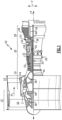
- FIG. 1 schematically illustrates an example gas turbine engine 20 that includes a fan section 22, a compressor section 24, a combustor section 26 and a turbine section 28.
- Alternative engines might include an augmenter section (not shown) among other systems or features.
- the fan section 22 drives air along a bypass flow path B while the compressor section 24 draws air in along a core airflow C along a core flow path where air is compressed and communicated to a combustor section 26.
- air is mixed with fuel and ignited to generate a high pressure exhaust gas stream that expands through the turbine section 28 where energy is extracted and utilized to drive the fan section 22 and the compressor section 24.
- turbofan gas turbine engine depicts a turbofan gas turbine engine
- the concepts described herein are not limited to use with turbofans as the teachings may be applied to other types of turbine engines; for example a turbine engine including a three-spool architecture in which three spools concentrically rotate about a common axis and where a low spool enables a low pressure turbine to drive a fan via a gearbox, an intermediate spool that enables an intermediate pressure turbine to drive a first compressor of the compressor section, and a high spool that enables a high pressure turbine to drive a high pressure compressor of the compressor section.
- the example engine 20 generally includes a low speed spool 30 and a high speed spool 32 mounted for rotation about an engine central longitudinal axis A relative to an engine static structure 36 via several bearing systems 38. It should be understood that various bearing systems 38 at various locations may alternatively or additionally be provided.
- the low speed spool 30 generally includes an inner shaft 40 that connects a fan 42 and a low pressure (or first) compressor section 44 to a low pressure (or first) turbine section 46.
- the inner shaft 40 drives the fan 42 through a speed change device, such as a geared architecture 48, to drive the fan 42 at a lower speed than the low speed spool 30.
- the high-speed spool 32 includes an outer shaft 50 that interconnects a high pressure (or second) compressor section 52 and a high pressure (or second) turbine section 54.
- the inner shaft 40 and the outer shaft 50 are concentric and rotate via the bearing systems 38 about the engine central longitudinal axis A.
- a combustor 56 is arranged between the high pressure compressor 52 and the high pressure turbine 54.
- the high pressure turbine 54 includes at least two stages to provide a double stage high pressure turbine 54.
- the high pressure turbine 54 includes only a single stage.
- a "high pressure" compressor or turbine experiences a higher pressure than a corresponding "low pressure” compressor or turbine.
- the example low pressure turbine 46 has a pressure ratio that is greater than about five (5).
- the pressure ratio of the example low pressure turbine 46 is measured prior to an inlet of the low pressure turbine 46 as related to the pressure measured at the outlet of the low pressure turbine 46 prior to an exhaust nozzle.
- a mid-turbine frame 57 of the engine static structure 36 is arranged generally between the high pressure turbine 54 and the low pressure turbine 46.
- the mid-turbine frame 57 further supports bearing systems 38 in the turbine section 28 as well as setting airflow entering the low pressure turbine 46.
- the core airflow C is compressed by the low pressure compressor 44 then by the high pressure compressor 52 mixed with fuel and ignited in the combustor 56 to produce high speed exhaust gases that are then expanded through the high pressure turbine 54 and low pressure turbine 46.
- the mid-turbine frame 57 includes vanes 59, which are in the core airflow path and function as an inlet guide vane for the low pressure turbine 46. Utilizing the vane 59 of the mid-turbine frame 57 as the inlet guide vane for low pressure turbine 46 decreases the length of the low pressure turbine 46 without increasing the axial length of the mid-turbine frame 57. Reducing or eliminating the number of vanes in the low pressure turbine 46 shortens the axial length of the turbine section 28. Thus, the compactness of the gas turbine engine 20 is increased and a higher power density may be achieved.
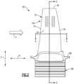
- FIG 2 is a side view of an engine component 62 according to this disclosure.
- the illustrated engine component 62 is a turbine blade. It should be understood that this disclosure extends to other engine components, such as compressor blades, stator vanes (e.g., Figures 8A-8B ), and fan blades, as non-limiting examples.
- the example engine component 62 includes an airfoil section 64, a root 66, and a platform 68.
- the root 66 includes a fir tree configuration.
- the airfoil section 64 includes a pressure side wall 70 and a suction side wall 72, each of which extend between a leading edge 74 and a trailing edge 76.
- the pressure side wall 70 and the suction side wall 72 extend radially from the platform 68 to a radially outer blade tip 78.
- the term "radially,” as used herein refers to the radial direction Z, which is normal to the engine central longitudinal axis A, and is used for purposes of explaining the relative location of the illustrated components without being otherwise limiting.
- the engine component 62 is a multiple piece engine component, as illustrated in Figure 3 , where the pressure side wall 70 and the suction side wall 72 are formed separately from the root 66 and the platform 68 of the engine component 62.
- the exposed airfoil flowpath section 64 is a separate structure from the root 66 and platform 68.
- the root 66, the platform 68, and a plurality of radial supports 80A-80D are integrally formed using a casting process, as explained in detail below relative to Figure 6 .
- a forging process is used. While in this example four radial supports 80A-80D are illustrated, it should be understood that there could be any number of radial supports.
- the pressure side wall 70 and the suction side wall 72 are separately formed using an additive manufacturing process, again, as will be explained below relative to Figure 6 , and after forming, the pressure side wall 70 and the suction side wall 72 are then joined to the radial supports 80A-80D to provide the airfoil section 64, as will be described in detail below.
- the pressure side wall 70 includes an outer surface 82 providing a portion of the outer contour of the airfoil section 64, and an inner surface 84 facing the radial supports 80A-80D.
- the pressure side wall 70 includes a plurality of radially extending slots 86A-86D.
- the slots 86A-86D extend generally parallel to one another, and have a longitudinal dimension extending generally in the radial direction Z.
- the slots 86A-86D correspond to a plurality of pressure side ribs 88A-88D extending from the radial supports 80A-80D in a direction perpendicular to the radial direction Z.
- the suction side wall 72 likewise includes an outer surface 90, an inner surface 92, and a plurality of slots 94A-94D which correspond to a plurality of suction side ribs 96A-96D extending from a suction side of the radial supports 80A-80D.
- the slots 86A-86D, 94A-94D and ribs 88A-88D, 96A-96D facilitate alignment of the pressure side wall 70 and the suction side wall 72 relative to the radial supports 80A-80D., which may increase the ease of assembly of the engine component 62.
- the adjacent surfaces of the slots 86A-86D, 94A-94D and ribs 88A-88D, 96A-96D (e.g., the surfaces that abut one another) provide joining interfaces for attachment (e.g., by welding). That is, the slots 86A-86D, 94A-94D and ribs 88A-88D, 96A-96D not only increase the ease of aligning the multiple pieces of the engine component 62, but also provide a joining interface for welding.
- the pressure side wall 70 can include a plurality of microchannels 98, 100 configured to direct a cooling flow of fluid from a core passageway 102 provided between the pressure and suction side walls 70, 72.
- the suction side wall 72 may likewise include a plurality of microchannels 104, 106 configured to direct a portion of fluid from the core passageway 102 outward toward the suction side wall.
- the illustrated microchannels 98, 100, 104, 106 are shown for illustrative purposes only.
- the pressure and suction side walls 70, 72 may include additional and/or different types of microchannels.
- Figure 5 is a view taken along line 5-5 from Figure 2 , and illustrates the detail of the interaction between the slots in the pressure and suction side walls 70, 72, and further illustrates the pressure and suction side walls 70, 72 joined to the radial supports 80A-80D.
- the pressure and suction side walls 70, 72 are welded (e.g., tack welded) to the radial supports 80A-80D.
- the pressure and suction side walls 70, 72 are brazed, diffusion bonded, or glued/cemented to the radial supports 80A-80D.
- Other techniques for joining the pressure side wall and suction side wall 70, 72 to the radial supports 80A-80D may be used herein.
- Figure 6 illustrates the method according to the invention for forming the engine component 62.
- the pressure and suction side walls 70, 72 are additively manufactured.
- a powdered metal may be selectively melted to form a first layer of the component.
- the powdered metal is a titanium alloy.
- the powdered metal is a molybdenum alloy.
- Other example alloys may be used herein, such as: (1) a titanium, (2) tungsten, (3) nickel, (4) cobalt, and (5) steel alloys.
- additional powdered metal is layered on top of the cooled metal, and is selectively melted to form another, subsequent layer.
- Example techniques include direct metal laser sintering (DMLS), electron beam melting (EBM), electron beam wire deposition (EBWD), and laser powder deposition (LPD).
- DMLS direct metal laser sintering
- EBM electron beam melting
- EBWD electron beam wire deposition
- LPD laser powder deposition
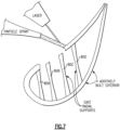
- Other types of additive manufacturing processes come within the scope of this disclosure. For instance, as illustrated in Figure 7 , an additive manufacturing process includes the use of a laser powder plasma spray (LPPS) process.
- LPPS laser powder plasma spray
- the root 66, the platform 68, and the radial supports 80A-80D are formed, at 110, in one example by way of casting, such as investment casting. In another example, a forging process is used. In either case, the root 66, the platform 68, and the radial supports 80A-80D may be formed of a single crystal, directionally solidified, or equiax alloy. Such alloys are generally more resistant to creep than materials suited for additive manufacturing.
- the pressure and suction side walls 70, 72 are joined to the casting formed at 110, by way of welding, or some other joining process, as mentioned above.
- microchannels 98, 100, 104, 106 in the pressure and suction side walls 70, 72 may be difficult to form by way of casting or forging.
- materials that are capable of being additively manufactured may be less resistant to creep and other stresses.
- this disclosure provides an engine component 62 with a first portion (e.g., the root, platform, and radial supports 80A-80D) having sufficient creep and other load-resistive capabilities, and second and third portions (the pressure and suction side walls 70, 72, for example) including relatively intricate microchannel cooling passageways for cooling the airfoil section 64.
- a first portion e.g., the root, platform, and radial supports 80A-80D
- second and third portions the pressure and suction side walls 70, 72, for example
- the pressure and suction side walls 70, 72 may be formed using different manufacturing techniques in the example when the pressure and suction side walls 70, 72 are made of a molybdenum alloy.
- the pressure and suction side walls 70, 72 could be formed using EDM, ECM, or other, more conventional machining techniques.
- an intermediate material coating may be applied to the internal casting at locations of expected contact between the pressure and suction side walls and the internal casting.
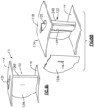
- an example stator vane 114 may include an inner platform 116, an outer platform 118, and a radial support 120 extending therebetween.
- the inner and outer platforms 116, 118 and the radial support 120 are formed using a casting or forging process.
- An airfoil section 122 of the vane 114 includes pressure and suction side sections 124A, 124B formed using an additive manufacturing process. Similar to the above example, the pressure and suction side sections 124A, 124B include slots 126 for receiving a corresponding rib 128 from the radial support 120.
- the vane 114 only includes a single radial support 120, although it should be understood that additional radial supports could be included.
Landscapes
- Engineering & Computer Science (AREA)
- Mechanical Engineering (AREA)
- Physics & Mathematics (AREA)
- Optics & Photonics (AREA)
- General Engineering & Computer Science (AREA)
- Plasma & Fusion (AREA)
- Manufacturing & Machinery (AREA)
- Chemical & Material Sciences (AREA)
- Materials Engineering (AREA)
- Architecture (AREA)
- Composite Materials (AREA)
- Turbine Rotor Nozzle Sealing (AREA)
- Powder Metallurgy (AREA)
- Forging (AREA)
Claims (5)
- Procédé de formation d'un composant (62) d'un moteur à turbine à gaz, comprenant :la formation d'une première partie du composant (62) à l'aide de l'un d'un processus de moulage ou de forgeage, la première partie comportant une racine (66), une plateforme (68) et au moins un support radial (80A-80D) faisant saillie depuis la plateforme (68) ;la fabrication de manière additive d'une deuxième partie (70, 72) du composant (62) ;l'assemblage de la deuxième partie (70, 72) à la première partie ;la fabrication de manière additive d'une troisième partie (70, 72) du composant (62) ; etl'assemblage de la troisième partie (70, 72) à la première partie, dans lequel :la deuxième partie (70, 72) et la troisième partie (70, 72) fournissent des parois latérales de pression et d'aspiration du composant (62) ; etl'au moins un support radial (80A-80D) comporte une pluralité de supports radiaux (80A-80D), chacun des supports radiaux comportant une première nervure (88A-88D, 96A-96D) et une seconde nervure (88A-88D, 96A-96D) faisant saillie dans des fentes (86A-86D, 94A-94D) formées dans la deuxième partie (70, 72) et la troisième partie (70, 72).
- Procédé selon la revendication 1, dans lequel la deuxième partie (70, 72) et la troisième partie (70, 72) comportent des microcanaux (98, 100, 104, 106) formés dans celles-ci.
- Procédé selon l'une quelconque des revendications 1 ou 2, dans lequel l'étape de fabrication additive comporte l'un d'un processus de frittage laser direct de métal (DMLS), un processus de fusion par faisceau d'électrons (EBM), un processus de dépôt de fil par faisceau d'électrons (EBWD), un processus de dépôt de poudre au laser (LPD) et un processus de pulvérisation de poudre au laser (LPPS).
- Procédé selon une quelconque revendication précédente, dans lequel la racine (66), la plateforme (68) et au moins un support radial (80A-80D) sont intégralement formés d'un monocristal, solidifié de manière directionnelle, ou d'un alliage équiaxial.
- Procédé selon une quelconque revendication précédente, dans lequel le composant (62) est une pale de rotor ou une aube de stator.
Priority Applications (1)
| Application Number | Priority Date | Filing Date | Title |
|---|---|---|---|
| EP23212789.4A EP4306233A3 (fr) | 2013-10-18 | 2014-10-17 | Procédé de formation d'un composant d'un moteur à turbine à gaz |
Applications Claiming Priority (2)
| Application Number | Priority Date | Filing Date | Title |
|---|---|---|---|
| US201361892763P | 2013-10-18 | 2013-10-18 | |
| PCT/US2014/061061 WO2015058043A1 (fr) | 2013-10-18 | 2014-10-17 | Composant de moteur multipièces |
Related Child Applications (1)
| Application Number | Title | Priority Date | Filing Date |
|---|---|---|---|
| EP23212789.4A Division EP4306233A3 (fr) | 2013-10-18 | 2014-10-17 | Procédé de formation d'un composant d'un moteur à turbine à gaz |
Publications (3)
| Publication Number | Publication Date |
|---|---|
| EP3058177A1 EP3058177A1 (fr) | 2016-08-24 |
| EP3058177A4 EP3058177A4 (fr) | 2017-03-15 |
| EP3058177B1 true EP3058177B1 (fr) | 2023-11-29 |
Family
ID=52828722
Family Applications (2)
| Application Number | Title | Priority Date | Filing Date |
|---|---|---|---|
| EP14853886.1A Active EP3058177B1 (fr) | 2013-10-18 | 2014-10-17 | Procédé de formation d'un composant d'un moteur à turbine à gaz |
| EP23212789.4A Pending EP4306233A3 (fr) | 2013-10-18 | 2014-10-17 | Procédé de formation d'un composant d'un moteur à turbine à gaz |
Family Applications After (1)
| Application Number | Title | Priority Date | Filing Date |
|---|---|---|---|
| EP23212789.4A Pending EP4306233A3 (fr) | 2013-10-18 | 2014-10-17 | Procédé de formation d'un composant d'un moteur à turbine à gaz |
Country Status (3)
| Country | Link |
|---|---|
| US (2) | US10329918B2 (fr) |
| EP (2) | EP3058177B1 (fr) |
| WO (1) | WO2015058043A1 (fr) |
Families Citing this family (29)
| Publication number | Priority date | Publication date | Assignee | Title |
|---|---|---|---|---|
| JP6245906B2 (ja) * | 2013-09-13 | 2017-12-13 | 公益財団法人鉄道総合技術研究所 | ブレーキディスク及びその製造方法 |
| EP3028793A1 (fr) | 2014-12-04 | 2016-06-08 | Siemens Aktiengesellschaft | Procédé de production d'une aube mobile |
| EP3128200B1 (fr) | 2015-08-05 | 2018-12-05 | Freni Brembo S.p.A. | Corps de mâchoire pour frein à disque et procédé de fabrication dudit corps |
| ITUB20152913A1 (it) | 2015-08-05 | 2017-02-05 | Freni Brembo Spa | Corpo pinza per freno a disco e metodo di fabbricazione di detto corpo pinza |
| EP3144485A1 (fr) * | 2015-09-16 | 2017-03-22 | Siemens Aktiengesellschaft | Composant de turbomachine avec des éléments de refroidissement et procédé de fabrication d'un tel composant |
| FR3043577B1 (fr) | 2015-11-17 | 2022-06-17 | Snecma | Procede de fabrication d'une preforme d'aube, d'une aube et d'un secteur de distributeur par fusion selective sur lit de poudre |
| DE102016203680A1 (de) * | 2016-03-07 | 2017-09-07 | Siemens Aktiengesellschaft | Vorrichtung zur Durchführung eines Selective Laser Melting Prozesses sowie damit hergestelltes Bauteil |
| US10443447B2 (en) | 2016-03-14 | 2019-10-15 | General Electric Company | Doubler attachment system |
| EP3239468A1 (fr) * | 2016-04-27 | 2017-11-01 | MTU Aero Engines GmbH | Procédé de fabrication d'une aube de turbomachine |
| US10975719B2 (en) * | 2017-01-05 | 2021-04-13 | General Electric Company | Process and printed article |
| US10830071B2 (en) * | 2017-01-23 | 2020-11-10 | General Electric Company | System and method for the hybrid construction of multi-piece parts |
| EP3431211B1 (fr) | 2017-07-20 | 2022-03-16 | General Electric Company | Procédés de fabrication d'un article hybride |
| US10724380B2 (en) * | 2017-08-07 | 2020-07-28 | General Electric Company | CMC blade with internal support |
| JP7024328B2 (ja) * | 2017-10-31 | 2022-02-24 | 株式会社Ihi | 金属部材の作製方法 |
| GB201720829D0 (en) * | 2017-12-14 | 2018-01-31 | Rolls Royce Plc | Aerofoil and method of manufacture |
| GB201720828D0 (en) | 2017-12-14 | 2018-01-31 | Rolls Royce Plc | Aerofoil |
| DE102018202685A1 (de) * | 2018-02-22 | 2019-08-22 | Siemens Aktiengesellschaft | Bauteil sowie Verfahren zum Herstellen eines Bauteils mittels additiven Fertigungsverfahren |
| US11426818B2 (en) | 2018-08-10 | 2022-08-30 | The Research Foundation for the State University | Additive manufacturing processes and additively manufactured products |
| CN109182843B (zh) * | 2018-09-07 | 2021-06-22 | 大连理工大学 | 一种镍钨中间合金及一种电子束熔炼制备镍钨中间合金的方法 |
| US10821678B2 (en) | 2018-11-09 | 2020-11-03 | Raytheon Technologies Corporation | Additive manufactured multi-portion article |
| DE102019201085A1 (de) * | 2019-01-29 | 2020-07-30 | Siemens Aktiengesellschaft | Herstellungsverfahren für ein Bauteil mit integrierten Kanälen |
| US20220111441A1 (en) * | 2019-02-14 | 2022-04-14 | Safran | Method of additive manufacturing with separation via a frangible zone |
| DE102019216569A1 (de) * | 2019-10-28 | 2021-04-29 | Siemens Energy Global GmbH & Co. KG | Bauteil sowie Verfahren zum Herstellen eines solchen Bauteils mittels additiver Herstellung |
| CN110695358B (zh) * | 2019-11-11 | 2020-11-06 | 北京理工大学 | 一种钛合金单晶叶片的丝材增材制造方法 |
| US12146419B1 (en) * | 2020-01-07 | 2024-11-19 | Rtx Corporation | Multi-alloy turbine engine components and manufacture methods |
| CN112122609A (zh) * | 2020-08-05 | 2020-12-25 | 北京航空航天大学 | 锻造和选区增材复合的金属构件制造方法 |
| GB202216827D0 (en) * | 2022-11-11 | 2022-12-28 | Rolls Royce Plc | A method of manufacturing a turbine component |
| US12196107B2 (en) | 2023-02-22 | 2025-01-14 | General Electric Company | Turbine engine with a blade having woven core and toughened region |
| US12601266B2 (en) | 2023-06-05 | 2026-04-14 | General Electric Company | Composite airfoil assembly for a turbine engine |
Family Cites Families (21)
| Publication number | Priority date | Publication date | Assignee | Title |
|---|---|---|---|---|
| US4519745A (en) * | 1980-09-19 | 1985-05-28 | Rockwell International Corporation | Rotor blade and stator vane using ceramic shell |
| US5425622A (en) | 1993-12-23 | 1995-06-20 | United Technologies Corporation | Turbine blade attachment means |
| US6347660B1 (en) | 1998-12-01 | 2002-02-19 | Howmet Research Corporation | Multipiece core assembly for cast airfoil |
| US7114554B2 (en) * | 2003-12-01 | 2006-10-03 | Honeywell International Inc. | Controller interface with multiple day programming |
| US7083388B2 (en) | 2004-04-29 | 2006-08-01 | United Technologies Corporation | Double near-net forging of article |
| US7189064B2 (en) | 2004-05-14 | 2007-03-13 | General Electric Company | Friction stir welded hollow airfoils and method therefor |
| US20070163114A1 (en) | 2006-01-13 | 2007-07-19 | General Electric Company | Methods for fabricating components |
| DE102007027465A1 (de) * | 2007-06-14 | 2008-12-18 | Rolls-Royce Deutschland Ltd & Co Kg | Gasturbinenschaufel mit modularem Aufbau |
| US20090081032A1 (en) | 2007-09-20 | 2009-03-26 | General Electric Company | Composite airfoil |
| US20110097213A1 (en) | 2009-03-24 | 2011-04-28 | Peretti Michael W | Composite airfoils having leading edge protection made using high temperature additive manufacturing methods |
| DE102009048665A1 (de) * | 2009-09-28 | 2011-03-31 | Siemens Aktiengesellschaft | Turbinenschaufel und Verfahren zu deren Herstellung |
| DE102009049707A1 (de) | 2009-10-17 | 2011-07-28 | MTU Aero Engines GmbH, 80995 | Verfahren zur Herstellung einer Lauf- oder Statorschaufel und eine derartige Schaufel |
| US8231354B2 (en) | 2009-12-15 | 2012-07-31 | Siemens Energy, Inc. | Turbine engine airfoil and platform assembly |
| US9175568B2 (en) | 2010-06-22 | 2015-11-03 | Honeywell International Inc. | Methods for manufacturing turbine components |
| US20120034101A1 (en) | 2010-08-09 | 2012-02-09 | James Allister W | Turbine blade squealer tip |
| US20120156054A1 (en) | 2010-12-15 | 2012-06-21 | General Electric Company | Turbine component with near-surface cooling passage and process therefor |
| US9085980B2 (en) | 2011-03-04 | 2015-07-21 | Honeywell International Inc. | Methods for repairing turbine components |
| US20120237351A1 (en) | 2011-03-17 | 2012-09-20 | Weisse Michael A | Retention for bonded hollow fan blade cover |
| US8899303B2 (en) | 2011-05-10 | 2014-12-02 | Howmet Corporation | Ceramic core with composite insert for casting airfoils |
| US9393620B2 (en) * | 2012-12-14 | 2016-07-19 | United Technologies Corporation | Uber-cooled turbine section component made by additive manufacturing |
| US10072503B2 (en) * | 2013-08-14 | 2018-09-11 | Elwha Llc | Dual element turbine blade |
-
2014
- 2014-10-17 EP EP14853886.1A patent/EP3058177B1/fr active Active
- 2014-10-17 US US15/030,243 patent/US10329918B2/en active Active
- 2014-10-17 EP EP23212789.4A patent/EP4306233A3/fr active Pending
- 2014-10-17 WO PCT/US2014/061061 patent/WO2015058043A1/fr not_active Ceased
-
2019
- 2019-05-10 US US16/408,751 patent/US11143034B2/en active Active
Also Published As
| Publication number | Publication date |
|---|---|
| US20190271229A1 (en) | 2019-09-05 |
| EP3058177A4 (fr) | 2017-03-15 |
| EP3058177A1 (fr) | 2016-08-24 |
| EP4306233A3 (fr) | 2024-04-03 |
| EP4306233A2 (fr) | 2024-01-17 |
| WO2015058043A1 (fr) | 2015-04-23 |
| US11143034B2 (en) | 2021-10-12 |
| US10329918B2 (en) | 2019-06-25 |
| US20160265362A1 (en) | 2016-09-15 |
Similar Documents
| Publication | Publication Date | Title |
|---|---|---|
| US11143034B2 (en) | Multiple piece engine component | |
| US10465543B2 (en) | Flow directing cover for engine component | |
| EP3027853B1 (fr) | Ensemble à surface aérodynamique en cmc pour moteur à turbine à gaz | |
| EP2867472B1 (fr) | Aube statorique de turbine | |
| EP2975217B1 (fr) | Utilisation d'inserts pour équilibrer le transfert de chaleur et les contraintes dans des alliages à haute température | |
| US20070163114A1 (en) | Methods for fabricating components | |
| CN106246237A (zh) | 具有近壁冷却特征的热气体路径部件 | |
| JP2016205390A (ja) | ガスタービンエンジンの隣接ノズルを配置するための方法 | |
| JP7242290B2 (ja) | エーロフォイルのための二部分冷却通路 | |
| US11149573B2 (en) | Airfoil with seal between end wall and airfoil section | |
| EP3078807A1 (fr) | Passages de refroidissement pour composant de moteur à turbine à gaz | |
| EP3323982B1 (fr) | Profil aérodynamique, moteur à turbine à gaz ayant un tel profil et procédé de fabrication d'un profil aérodynamique | |
| US20200040743A1 (en) | Turbomachine Cooling Trench | |
| EP3047106B1 (fr) | Profil aérodynamique de moteur à turbine à gaz comportant un passage de refroidissement de plate-forme alimenté par un serpentin | |
| EP3498971B1 (fr) | Profil d'aube pour moteur à turbine à gaz comprenant une feuille de division | |
| US20190323359A1 (en) | Blade and a method of manufacturing a blade | |
| EP3412868B1 (fr) | Aube statorique avec refroidissement fendu à débit réglable de plate-forme pour turbine à gaz | |
| KR102921062B1 (ko) | 가스 터빈용 블레이드의 제조 방법, 터빈 블레이드, 및 가스 터빈 | |
| EP3495615A1 (fr) | Profil aérodynamique avec des passages de refroidissement internes | |
| KR20240158732A (ko) | 가스 터빈용 블레이드의 제조 방법, 터빈 블레이드, 및 가스 터빈 | |
| EP3495619A1 (fr) | Profil aérodynamique avec des passages de refroidissement internes |
Legal Events
| Date | Code | Title | Description |
|---|---|---|---|
| PUAI | Public reference made under article 153(3) epc to a published international application that has entered the european phase |
Free format text: ORIGINAL CODE: 0009012 |
|
| TPAC | Observations filed by third parties |
Free format text: ORIGINAL CODE: EPIDOSNTIPA |
|
| 17P | Request for examination filed |
Effective date: 20160517 |
|
| AK | Designated contracting states |
Kind code of ref document: A1 Designated state(s): AL AT BE BG CH CY CZ DE DK EE ES FI FR GB GR HR HU IE IS IT LI LT LU LV MC MK MT NL NO PL PT RO RS SE SI SK SM TR |
|
| AX | Request for extension of the european patent |
Extension state: BA ME |
|
| RAP1 | Party data changed (applicant data changed or rights of an application transferred) |
Owner name: UNITED TECHNOLOGIES CORPORATION |
|
| RIN1 | Information on inventor provided before grant (corrected) |
Inventor name: ZELESKY, MARK F. Inventor name: SLAVENS, THOMAS N. |
|
| DAX | Request for extension of the european patent (deleted) | ||
| A4 | Supplementary search report drawn up and despatched |
Effective date: 20170214 |
|
| RIC1 | Information provided on ipc code assigned before grant |
Ipc: B22D 25/02 20060101ALI20170208BHEP Ipc: B22D 25/00 20060101ALI20170208BHEP Ipc: B23K 10/02 20060101ALI20170208BHEP Ipc: B22F 3/105 20060101ALI20170208BHEP Ipc: B22F 7/08 20060101ALI20170208BHEP Ipc: B23K 15/00 20060101ALI20170208BHEP Ipc: B22F 5/04 20060101ALI20170208BHEP Ipc: B23K 31/00 20060101ALI20170208BHEP Ipc: B22F 3/24 20060101ALI20170208BHEP Ipc: B23K 1/00 20060101ALI20170208BHEP Ipc: B21K 3/04 20060101ALI20170208BHEP Ipc: F01D 9/02 20060101ALI20170208BHEP Ipc: F01D 5/18 20060101ALI20170208BHEP Ipc: F01D 5/14 20060101AFI20170208BHEP |
|
| STAA | Information on the status of an ep patent application or granted ep patent |
Free format text: STATUS: REQUEST FOR EXAMINATION WAS MADE |
|
| STAA | Information on the status of an ep patent application or granted ep patent |
Free format text: STATUS: EXAMINATION IS IN PROGRESS |
|
| 17Q | First examination report despatched |
Effective date: 20191115 |
|
| RAP1 | Party data changed (applicant data changed or rights of an application transferred) |
Owner name: RAYTHEON TECHNOLOGIES CORPORATION |
|
| GRAP | Despatch of communication of intention to grant a patent |
Free format text: ORIGINAL CODE: EPIDOSNIGR1 |
|
| STAA | Information on the status of an ep patent application or granted ep patent |
Free format text: STATUS: GRANT OF PATENT IS INTENDED |
|
| INTG | Intention to grant announced |
Effective date: 20230517 |
|
| RIN1 | Information on inventor provided before grant (corrected) |
Inventor name: ZELESKY, MARK F. Inventor name: SLAVENS, THOMAS N. |
|
| GRAS | Grant fee paid |
Free format text: ORIGINAL CODE: EPIDOSNIGR3 |
|
| GRAA | (expected) grant |
Free format text: ORIGINAL CODE: 0009210 |
|
| STAA | Information on the status of an ep patent application or granted ep patent |
Free format text: STATUS: THE PATENT HAS BEEN GRANTED |
|
| RAP3 | Party data changed (applicant data changed or rights of an application transferred) |
Owner name: RTX CORPORATION |
|
| AK | Designated contracting states |
Kind code of ref document: B1 Designated state(s): AL AT BE BG CH CY CZ DE DK EE ES FI FR GB GR HR HU IE IS IT LI LT LU LV MC MK MT NL NO PL PT RO RS SE SI SK SM TR |
|
| REG | Reference to a national code |
Ref country code: GB Ref legal event code: FG4D |
|
| REG | Reference to a national code |
Ref country code: CH Ref legal event code: EP |
|
| REG | Reference to a national code |
Ref country code: DE Ref legal event code: R096 Ref document number: 602014089005 Country of ref document: DE |
|
| REG | Reference to a national code |
Ref country code: IE Ref legal event code: FG4D |
|
| REG | Reference to a national code |
Ref country code: LT Ref legal event code: MG9D |
|
| REG | Reference to a national code |
Ref country code: NL Ref legal event code: MP Effective date: 20231129 |
|
| PG25 | Lapsed in a contracting state [announced via postgrant information from national office to epo] |
Ref country code: GR Free format text: LAPSE BECAUSE OF FAILURE TO SUBMIT A TRANSLATION OF THE DESCRIPTION OR TO PAY THE FEE WITHIN THE PRESCRIBED TIME-LIMIT Effective date: 20240301 |
|
| PG25 | Lapsed in a contracting state [announced via postgrant information from national office to epo] |
Ref country code: IS Free format text: LAPSE BECAUSE OF FAILURE TO SUBMIT A TRANSLATION OF THE DESCRIPTION OR TO PAY THE FEE WITHIN THE PRESCRIBED TIME-LIMIT Effective date: 20240329 |
|
| PG25 | Lapsed in a contracting state [announced via postgrant information from national office to epo] |
Ref country code: LT Free format text: LAPSE BECAUSE OF FAILURE TO SUBMIT A TRANSLATION OF THE DESCRIPTION OR TO PAY THE FEE WITHIN THE PRESCRIBED TIME-LIMIT Effective date: 20231129 |
|
| PG25 | Lapsed in a contracting state [announced via postgrant information from national office to epo] |
Ref country code: ES Free format text: LAPSE BECAUSE OF FAILURE TO SUBMIT A TRANSLATION OF THE DESCRIPTION OR TO PAY THE FEE WITHIN THE PRESCRIBED TIME-LIMIT Effective date: 20231129 |
|
| PG25 | Lapsed in a contracting state [announced via postgrant information from national office to epo] |
Ref country code: LT Free format text: LAPSE BECAUSE OF FAILURE TO SUBMIT A TRANSLATION OF THE DESCRIPTION OR TO PAY THE FEE WITHIN THE PRESCRIBED TIME-LIMIT Effective date: 20231129 Ref country code: IS Free format text: LAPSE BECAUSE OF FAILURE TO SUBMIT A TRANSLATION OF THE DESCRIPTION OR TO PAY THE FEE WITHIN THE PRESCRIBED TIME-LIMIT Effective date: 20240329 Ref country code: GR Free format text: LAPSE BECAUSE OF FAILURE TO SUBMIT A TRANSLATION OF THE DESCRIPTION OR TO PAY THE FEE WITHIN THE PRESCRIBED TIME-LIMIT Effective date: 20240301 Ref country code: ES Free format text: LAPSE BECAUSE OF FAILURE TO SUBMIT A TRANSLATION OF THE DESCRIPTION OR TO PAY THE FEE WITHIN THE PRESCRIBED TIME-LIMIT Effective date: 20231129 Ref country code: BG Free format text: LAPSE BECAUSE OF FAILURE TO SUBMIT A TRANSLATION OF THE DESCRIPTION OR TO PAY THE FEE WITHIN THE PRESCRIBED TIME-LIMIT Effective date: 20240229 |
|
| REG | Reference to a national code |
Ref country code: AT Ref legal event code: MK05 Ref document number: 1636308 Country of ref document: AT Kind code of ref document: T Effective date: 20231129 |
|
| PG25 | Lapsed in a contracting state [announced via postgrant information from national office to epo] |
Ref country code: NL Free format text: LAPSE BECAUSE OF FAILURE TO SUBMIT A TRANSLATION OF THE DESCRIPTION OR TO PAY THE FEE WITHIN THE PRESCRIBED TIME-LIMIT Effective date: 20231129 |
|
| PG25 | Lapsed in a contracting state [announced via postgrant information from national office to epo] |
Ref country code: SE Free format text: LAPSE BECAUSE OF FAILURE TO SUBMIT A TRANSLATION OF THE DESCRIPTION OR TO PAY THE FEE WITHIN THE PRESCRIBED TIME-LIMIT Effective date: 20231129 Ref country code: RS Free format text: LAPSE BECAUSE OF FAILURE TO SUBMIT A TRANSLATION OF THE DESCRIPTION OR TO PAY THE FEE WITHIN THE PRESCRIBED TIME-LIMIT Effective date: 20231129 Ref country code: PL Free format text: LAPSE BECAUSE OF FAILURE TO SUBMIT A TRANSLATION OF THE DESCRIPTION OR TO PAY THE FEE WITHIN THE PRESCRIBED TIME-LIMIT Effective date: 20231129 Ref country code: NO Free format text: LAPSE BECAUSE OF FAILURE TO SUBMIT A TRANSLATION OF THE DESCRIPTION OR TO PAY THE FEE WITHIN THE PRESCRIBED TIME-LIMIT Effective date: 20240229 Ref country code: NL Free format text: LAPSE BECAUSE OF FAILURE TO SUBMIT A TRANSLATION OF THE DESCRIPTION OR TO PAY THE FEE WITHIN THE PRESCRIBED TIME-LIMIT Effective date: 20231129 Ref country code: LV Free format text: LAPSE BECAUSE OF FAILURE TO SUBMIT A TRANSLATION OF THE DESCRIPTION OR TO PAY THE FEE WITHIN THE PRESCRIBED TIME-LIMIT Effective date: 20231129 Ref country code: HR Free format text: LAPSE BECAUSE OF FAILURE TO SUBMIT A TRANSLATION OF THE DESCRIPTION OR TO PAY THE FEE WITHIN THE PRESCRIBED TIME-LIMIT Effective date: 20231129 |
|
| PG25 | Lapsed in a contracting state [announced via postgrant information from national office to epo] |
Ref country code: DK Free format text: LAPSE BECAUSE OF FAILURE TO SUBMIT A TRANSLATION OF THE DESCRIPTION OR TO PAY THE FEE WITHIN THE PRESCRIBED TIME-LIMIT Effective date: 20231129 |
|
| PG25 | Lapsed in a contracting state [announced via postgrant information from national office to epo] |
Ref country code: AT Free format text: LAPSE BECAUSE OF FAILURE TO SUBMIT A TRANSLATION OF THE DESCRIPTION OR TO PAY THE FEE WITHIN THE PRESCRIBED TIME-LIMIT Effective date: 20231129 Ref country code: CZ Free format text: LAPSE BECAUSE OF FAILURE TO SUBMIT A TRANSLATION OF THE DESCRIPTION OR TO PAY THE FEE WITHIN THE PRESCRIBED TIME-LIMIT Effective date: 20231129 |
|
| PG25 | Lapsed in a contracting state [announced via postgrant information from national office to epo] |
Ref country code: SK Free format text: LAPSE BECAUSE OF FAILURE TO SUBMIT A TRANSLATION OF THE DESCRIPTION OR TO PAY THE FEE WITHIN THE PRESCRIBED TIME-LIMIT Effective date: 20231129 |
|
| PG25 | Lapsed in a contracting state [announced via postgrant information from national office to epo] |
Ref country code: SM Free format text: LAPSE BECAUSE OF FAILURE TO SUBMIT A TRANSLATION OF THE DESCRIPTION OR TO PAY THE FEE WITHIN THE PRESCRIBED TIME-LIMIT Effective date: 20231129 Ref country code: SK Free format text: LAPSE BECAUSE OF FAILURE TO SUBMIT A TRANSLATION OF THE DESCRIPTION OR TO PAY THE FEE WITHIN THE PRESCRIBED TIME-LIMIT Effective date: 20231129 Ref country code: RO Free format text: LAPSE BECAUSE OF FAILURE TO SUBMIT A TRANSLATION OF THE DESCRIPTION OR TO PAY THE FEE WITHIN THE PRESCRIBED TIME-LIMIT Effective date: 20231129 Ref country code: IT Free format text: LAPSE BECAUSE OF FAILURE TO SUBMIT A TRANSLATION OF THE DESCRIPTION OR TO PAY THE FEE WITHIN THE PRESCRIBED TIME-LIMIT Effective date: 20231129 Ref country code: EE Free format text: LAPSE BECAUSE OF FAILURE TO SUBMIT A TRANSLATION OF THE DESCRIPTION OR TO PAY THE FEE WITHIN THE PRESCRIBED TIME-LIMIT Effective date: 20231129 Ref country code: DK Free format text: LAPSE BECAUSE OF FAILURE TO SUBMIT A TRANSLATION OF THE DESCRIPTION OR TO PAY THE FEE WITHIN THE PRESCRIBED TIME-LIMIT Effective date: 20231129 Ref country code: CZ Free format text: LAPSE BECAUSE OF FAILURE TO SUBMIT A TRANSLATION OF THE DESCRIPTION OR TO PAY THE FEE WITHIN THE PRESCRIBED TIME-LIMIT Effective date: 20231129 Ref country code: AT Free format text: LAPSE BECAUSE OF FAILURE TO SUBMIT A TRANSLATION OF THE DESCRIPTION OR TO PAY THE FEE WITHIN THE PRESCRIBED TIME-LIMIT Effective date: 20231129 |
|
| PG25 | Lapsed in a contracting state [announced via postgrant information from national office to epo] |
Ref country code: PT Free format text: LAPSE BECAUSE OF FAILURE TO SUBMIT A TRANSLATION OF THE DESCRIPTION OR TO PAY THE FEE WITHIN THE PRESCRIBED TIME-LIMIT Effective date: 20240401 |
|
| PG25 | Lapsed in a contracting state [announced via postgrant information from national office to epo] |
Ref country code: PT Free format text: LAPSE BECAUSE OF FAILURE TO SUBMIT A TRANSLATION OF THE DESCRIPTION OR TO PAY THE FEE WITHIN THE PRESCRIBED TIME-LIMIT Effective date: 20240401 |
|
| REG | Reference to a national code |
Ref country code: DE Ref legal event code: R097 Ref document number: 602014089005 Country of ref document: DE |
|
| PLBE | No opposition filed within time limit |
Free format text: ORIGINAL CODE: 0009261 |
|
| STAA | Information on the status of an ep patent application or granted ep patent |
Free format text: STATUS: NO OPPOSITION FILED WITHIN TIME LIMIT |
|
| PG25 | Lapsed in a contracting state [announced via postgrant information from national office to epo] |
Ref country code: SI Free format text: LAPSE BECAUSE OF FAILURE TO SUBMIT A TRANSLATION OF THE DESCRIPTION OR TO PAY THE FEE WITHIN THE PRESCRIBED TIME-LIMIT Effective date: 20231129 |
|
| PG25 | Lapsed in a contracting state [announced via postgrant information from national office to epo] |
Ref country code: SI Free format text: LAPSE BECAUSE OF FAILURE TO SUBMIT A TRANSLATION OF THE DESCRIPTION OR TO PAY THE FEE WITHIN THE PRESCRIBED TIME-LIMIT Effective date: 20231129 |
|
| 26N | No opposition filed |
Effective date: 20240830 |
|
| REG | Reference to a national code |
Ref country code: CH Ref legal event code: PL |
|
| PG25 | Lapsed in a contracting state [announced via postgrant information from national office to epo] |
Ref country code: MC Free format text: LAPSE BECAUSE OF FAILURE TO SUBMIT A TRANSLATION OF THE DESCRIPTION OR TO PAY THE FEE WITHIN THE PRESCRIBED TIME-LIMIT Effective date: 20231129 |
|
| PG25 | Lapsed in a contracting state [announced via postgrant information from national office to epo] |
Ref country code: BE Free format text: LAPSE BECAUSE OF NON-PAYMENT OF DUE FEES Effective date: 20241031 Ref country code: LU Free format text: LAPSE BECAUSE OF NON-PAYMENT OF DUE FEES Effective date: 20241017 |
|
| PG25 | Lapsed in a contracting state [announced via postgrant information from national office to epo] |
Ref country code: CH Free format text: LAPSE BECAUSE OF NON-PAYMENT OF DUE FEES Effective date: 20241031 |
|
| REG | Reference to a national code |
Ref country code: BE Ref legal event code: MM Effective date: 20241031 |
|
| PG25 | Lapsed in a contracting state [announced via postgrant information from national office to epo] |
Ref country code: FI Free format text: LAPSE BECAUSE OF FAILURE TO SUBMIT A TRANSLATION OF THE DESCRIPTION OR TO PAY THE FEE WITHIN THE PRESCRIBED TIME-LIMIT Effective date: 20231129 |
|
| PGFP | Annual fee paid to national office [announced via postgrant information from national office to epo] |
Ref country code: GB Payment date: 20250923 Year of fee payment: 12 |
|
| PGFP | Annual fee paid to national office [announced via postgrant information from national office to epo] |
Ref country code: FR Payment date: 20250924 Year of fee payment: 12 |
|
| PG25 | Lapsed in a contracting state [announced via postgrant information from national office to epo] |
Ref country code: IE Free format text: LAPSE BECAUSE OF NON-PAYMENT OF DUE FEES Effective date: 20241017 |
|
| PGFP | Annual fee paid to national office [announced via postgrant information from national office to epo] |
Ref country code: DE Payment date: 20250923 Year of fee payment: 12 |
|
| P01 | Opt-out of the competence of the unified patent court (upc) registered |
Free format text: CASE NUMBER: UPC_APP_0016962_3058177/2025 Effective date: 20251210 |
|
| PG25 | Lapsed in a contracting state [announced via postgrant information from national office to epo] |
Ref country code: CY Free format text: LAPSE BECAUSE OF FAILURE TO SUBMIT A TRANSLATION OF THE DESCRIPTION OR TO PAY THE FEE WITHIN THE PRESCRIBED TIME-LIMIT; INVALID AB INITIO Effective date: 20141017 |
|
| PG25 | Lapsed in a contracting state [announced via postgrant information from national office to epo] |
Ref country code: HU Free format text: LAPSE BECAUSE OF FAILURE TO SUBMIT A TRANSLATION OF THE DESCRIPTION OR TO PAY THE FEE WITHIN THE PRESCRIBED TIME-LIMIT; INVALID AB INITIO Effective date: 20141017 |