EP1586746A2 - Procédé de réglage de la course de la bille d'un élément de rattrapage hydraulique de jeu aux soupapes - Google Patents
Procédé de réglage de la course de la bille d'un élément de rattrapage hydraulique de jeu aux soupapes Download PDFInfo
- Publication number
- EP1586746A2 EP1586746A2 EP20050006696 EP05006696A EP1586746A2 EP 1586746 A2 EP1586746 A2 EP 1586746A2 EP 20050006696 EP20050006696 EP 20050006696 EP 05006696 A EP05006696 A EP 05006696A EP 1586746 A2 EP1586746 A2 EP 1586746A2
- Authority
- EP
- European Patent Office
- Prior art keywords
- valve
- ball
- cap
- stroke
- measuring
- Prior art date
- Legal status (The legal status is an assumption and is not a legal conclusion. Google has not performed a legal analysis and makes no representation as to the accuracy of the status listed.)
- Granted
Links
- 238000000034 method Methods 0.000 title claims abstract description 15
- 238000003825 pressing Methods 0.000 claims description 3
- 238000005259 measurement Methods 0.000 abstract description 3
- 238000002485 combustion reaction Methods 0.000 description 1
- 238000010276 construction Methods 0.000 description 1
- 238000009434 installation Methods 0.000 description 1
- 238000004519 manufacturing process Methods 0.000 description 1
Images

Classifications
-
- F—MECHANICAL ENGINEERING; LIGHTING; HEATING; WEAPONS; BLASTING
- F01—MACHINES OR ENGINES IN GENERAL; ENGINE PLANTS IN GENERAL; STEAM ENGINES
- F01L—CYCLICALLY OPERATING VALVES FOR MACHINES OR ENGINES
- F01L1/00—Valve-gear or valve arrangements, e.g. lift-valve gear
- F01L1/20—Adjusting or compensating clearance
- F01L1/22—Adjusting or compensating clearance automatically, e.g. mechanically
- F01L1/24—Adjusting or compensating clearance automatically, e.g. mechanically by fluid means, e.g. hydraulically
- F01L1/245—Hydraulic tappets
-
- F—MECHANICAL ENGINEERING; LIGHTING; HEATING; WEAPONS; BLASTING
- F16—ENGINEERING ELEMENTS AND UNITS; GENERAL MEASURES FOR PRODUCING AND MAINTAINING EFFECTIVE FUNCTIONING OF MACHINES OR INSTALLATIONS; THERMAL INSULATION IN GENERAL
- F16K—VALVES; TAPS; COCKS; ACTUATING-FLOATS; DEVICES FOR VENTING OR AERATING
- F16K15/00—Check valves
- F16K15/02—Check valves with guided rigid valve members
- F16K15/04—Check valves with guided rigid valve members shaped as balls
- F16K15/044—Check valves with guided rigid valve members shaped as balls spring-loaded
-
- Y—GENERAL TAGGING OF NEW TECHNOLOGICAL DEVELOPMENTS; GENERAL TAGGING OF CROSS-SECTIONAL TECHNOLOGIES SPANNING OVER SEVERAL SECTIONS OF THE IPC; TECHNICAL SUBJECTS COVERED BY FORMER USPC CROSS-REFERENCE ART COLLECTIONS [XRACs] AND DIGESTS
- Y10—TECHNICAL SUBJECTS COVERED BY FORMER USPC
- Y10T—TECHNICAL SUBJECTS COVERED BY FORMER US CLASSIFICATION
- Y10T137/00—Fluid handling
- Y10T137/0318—Processes
- Y10T137/0402—Cleaning, repairing, or assembling
- Y10T137/0491—Valve or valve element assembling, disassembling, or replacing
- Y10T137/0497—Fluid actuated or retarded
-
- Y—GENERAL TAGGING OF NEW TECHNOLOGICAL DEVELOPMENTS; GENERAL TAGGING OF CROSS-SECTIONAL TECHNOLOGIES SPANNING OVER SEVERAL SECTIONS OF THE IPC; TECHNICAL SUBJECTS COVERED BY FORMER USPC CROSS-REFERENCE ART COLLECTIONS [XRACs] AND DIGESTS
- Y10—TECHNICAL SUBJECTS COVERED BY FORMER USPC
- Y10T—TECHNICAL SUBJECTS COVERED BY FORMER US CLASSIFICATION
- Y10T137/00—Fluid handling
- Y10T137/598—With repair, tapping, assembly, or disassembly means
- Y10T137/6086—Assembling or disassembling check valve
-
- Y—GENERAL TAGGING OF NEW TECHNOLOGICAL DEVELOPMENTS; GENERAL TAGGING OF CROSS-SECTIONAL TECHNOLOGIES SPANNING OVER SEVERAL SECTIONS OF THE IPC; TECHNICAL SUBJECTS COVERED BY FORMER USPC CROSS-REFERENCE ART COLLECTIONS [XRACs] AND DIGESTS
- Y10—TECHNICAL SUBJECTS COVERED BY FORMER USPC
- Y10T—TECHNICAL SUBJECTS COVERED BY FORMER US CLASSIFICATION
- Y10T137/00—Fluid handling
- Y10T137/7722—Line condition change responsive valves
- Y10T137/7837—Direct response valves [i.e., check valve type]
- Y10T137/7904—Reciprocating valves
- Y10T137/7922—Spring biased
- Y10T137/7927—Ball valves
Definitions
- the invention relates to a method for adjusting the ball stroke of a Valve ball formed valve closing body of the control valve of a hydraulic Valve clearance compensation element, in particular according to the preamble of Method claims 1 and 2.
- Well-known valve lash adjusters that are available as standard, freeball or reverse spring versions can be trained, among other things have one Piston, with a piston head, which has a central bore, at the Outboard end of the valve seat of a control valve is provided, the is dominated by a valve ball whose ball stroke through a valve cap is limited, which has a cap flange and a cap bottom, wherein the cap flange with its bearing surface on a depression of the piston crown rests and the inside of the cap base of the valve ball as a stop surface serves.
- valve clearance compensation elements have the disadvantage that due to process-related, not further vergbare manufacturing tolerances considerable Kugelhubstreuungen and, as a consequence thereof, corresponding pre-lift losses of Valve clearance compensation elements occur. These affect depending on Kugelhubtoleranzlage during cold start or in the high temperature phase of the internal combustion engine different. When cold starting is a medium to large ball stroke desired, in the high-temperature phase, a small to medium. Therefore is a tight tolerated, medium ball stroke the ideal compromise.
- the two measured values allow the determination a calculated ball stroke whose deviation from the desired Ball stroke the required diameter of the valve ball to be installed results. In this way, the matching components are present determined by their installation. As a result, a subsequent control of the Ball hubs in assembled state.
- An alternative method for setting the setpoint of the ball stroke Valve ball of a control valve of a valve clearance compensation element consists according to the independent method claim 2 in that the actual value of Ball strokes one with any ball valve and any valve cap assembled control valve and by pressing the valve cap is set to its desired value.
- Figure 1 is a longitudinal section through a hydraulic valve clearance compensation element shown in standard design, with a piston 1, which has a piston crown 2 having a central bore 3. This possesses at her outer end 4 a valve seat 5, of a valve ball 6 of a Control valve 7 is controlled.
- the control valve 7 has a valve cap 8, which has a cap flange 9 with a support surface 10 and a cap base 11 with a Nachdschreibmulde 18, whose inner surface serves as a stop 12 for the valve ball 6.
- the Support surface 10 is located in a recess 13 of the piston crown 2 on a in Figure 3 numbered bottom 17 and is centered on the edge 14 of the same. Since the Edge 14 of the recess 13 pulled something and the valve cap 8 resilient is formed, the same is clipped into the recess 13 during assembly.
- the stop 12 serves the valve ball 6 as a stroke limiter and a ball spring 15 as a guide and edition. The same applies to the present here Standard version of the control valve 7, the valve ball 6 in the direction of the valve seat 5th
- the outside of the stopper 12 is formed as Nachdrückmulde 18 whose Function is explained in the description of Figure 4.
- a depth inside dimension a between the support surface 10 and the stop 12th the valve cap 8 and a Vorstehdroit b of the measuring ball 16 relative to the Floor 17 of the recess 13 result in a calculated ball stroke c as the difference from a and b.
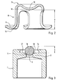
- valve cap 2 shows an enlarged longitudinal section of the valve cap 8, with the cap flange 9 and the bearing surface 10 and the cap bottom 11 and its stop 12.
- the depth internal dimension a is determined by the distance the bearing surface 10 and the stop 12 of the valve cap 8 fixed.
- FIG. 3 shows the piston 1 with the piston head 2, which has the central bore 3 having the valve seat 5, in which a measuring ball 16 is located.
- the Depression 13 with the edge 14 and the bottom 17 shown on the the Vorstehdroit b of the measuring ball 16 refers.
- the internal depth dimension a of any valve cap 8 and the Vorstehdroit b measured a measuring ball 16 in any piston 1.
- the Difference of the measured values a - b gives the calculated ball stroke c. This will usually differ from the desired ball stroke.
- the difference determined from the calculated ball stroke c and the desired ball stroke the deviation of the diameter of the zuzupodenden valve ball 6 from Diameter of the measuring ball 16 in order to achieve the desired stroke of the valve ball 6.
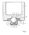
- Figure 4 is a longitudinal section through a standard version of a hydraulic Valve play compensation element shown in Figure 1. Since the reference numerals of FIG. 4 and FIG. 1, the description of FIG directed. However, the valve ball 6 is an arbitrary and at the ball stroke d to a measured or corrected ball stroke.
- the desired stroke of the valve ball 6 is achieved by pressing the valve cap 8, whose material allows a permanent deformation.
- a suitable one Tool for reprints is set in the Nachdrückmulde 18. Of the Isthub the valve ball 6 is before and after the deformation of the valve cap. 8 measured or controlled.
Landscapes
- Engineering & Computer Science (AREA)
- General Engineering & Computer Science (AREA)
- Mechanical Engineering (AREA)
- Valve-Gear Or Valve Arrangements (AREA)
Applications Claiming Priority (2)
| Application Number | Priority Date | Filing Date | Title |
|---|---|---|---|
| DE200410018386 DE102004018386A1 (de) | 2004-04-16 | 2004-04-16 | Verfahren zum Einstellen des Kugelhubs eines Ventilspielausgleichselements |
| DE102004018386 | 2004-04-16 |
Publications (3)
| Publication Number | Publication Date |
|---|---|
| EP1586746A2 true EP1586746A2 (fr) | 2005-10-19 |
| EP1586746A3 EP1586746A3 (fr) | 2009-06-03 |
| EP1586746B1 EP1586746B1 (fr) | 2011-08-24 |
Family
ID=34934540
Family Applications (1)
| Application Number | Title | Priority Date | Filing Date |
|---|---|---|---|
| EP20050006696 Expired - Lifetime EP1586746B1 (fr) | 2004-04-16 | 2005-03-26 | Procédé de réglage de la course de la bille d'un élément de rattrapage hydraulique de jeu aux soupapes |
Country Status (3)
| Country | Link |
|---|---|
| US (1) | US7392819B2 (fr) |
| EP (1) | EP1586746B1 (fr) |
| DE (1) | DE102004018386A1 (fr) |
Cited By (1)
| Publication number | Priority date | Publication date | Assignee | Title |
|---|---|---|---|---|
| CN115963773A (zh) * | 2022-12-28 | 2023-04-14 | 苏州明良智能科技有限公司 | 基于plc控制平台的微型轴承配对方法、系统和plc |
Families Citing this family (7)
| Publication number | Priority date | Publication date | Assignee | Title |
|---|---|---|---|---|
| JP2008076031A (ja) * | 2006-09-25 | 2008-04-03 | Denso Corp | 膨張弁 |
| DE102007046829A1 (de) * | 2007-09-29 | 2009-04-02 | Schaeffler Kg | Hydraulisches Ventilspielausgleichselement |
| US20110186152A1 (en) * | 2010-01-29 | 2011-08-04 | Continental Automotive Systems Us, Inc. | Compact Flow-Through Fuel Pressure Regulator |
| US20110186763A1 (en) * | 2010-02-04 | 2011-08-04 | Lamb Kevin W | Pressure by-pass valve |
| JP7101588B2 (ja) | 2018-10-18 | 2022-07-15 | 株式会社オティックス | ラッシュアジャスタ |
| JP7058206B2 (ja) * | 2018-10-18 | 2022-04-21 | 株式会社オティックス | ラッシュアジャスタ |
| US11339688B2 (en) | 2020-01-29 | 2022-05-24 | Borgwarner, Inc. | Variable camshaft timing valve assembly |
Citations (1)
| Publication number | Priority date | Publication date | Assignee | Title |
|---|---|---|---|---|
| US5622147A (en) | 1996-03-08 | 1997-04-22 | Eaton Corporation | Hydraulic lash adjuster |
Family Cites Families (24)
| Publication number | Priority date | Publication date | Assignee | Title |
|---|---|---|---|---|
| US2797673A (en) * | 1954-12-10 | 1957-07-02 | Gen Motors Corp | Valve lifter |
| US2922432A (en) * | 1957-05-09 | 1960-01-26 | Ross Operating Valve Co | Reversible cartridge speed control valve |
| US3421547A (en) * | 1965-11-30 | 1969-01-14 | Alkon Products Corp | Check valve mechanism |
| US3502058A (en) * | 1966-02-24 | 1970-03-24 | Earl A Thompson | Rocker arm |
| US3605707A (en) * | 1969-12-04 | 1971-09-20 | Eaton Yale & Towne | Hydraulic valve lifter with pump-up prevention means |
| US3875908A (en) * | 1973-06-18 | 1975-04-08 | Eaton Corp | Valve gear and lash adjuster for same |
| US4227495A (en) * | 1978-09-21 | 1980-10-14 | Eaton Corporation | Hydraulic lash adjuster with oil reservoir separator |
| US4271796A (en) * | 1979-06-11 | 1981-06-09 | The Jacobs Manufacturing Company | Pressure relief system for engine brake |
| JPS58154802U (ja) * | 1982-04-12 | 1983-10-17 | アイシン精機株式会社 | 油圧リフタ |
| US4807576A (en) * | 1985-10-15 | 1989-02-28 | Honda Giken Kogyo Kabushiki Kaisha | Hydraulic lash adjuster for use in valve operating mechanism |
| JPH063124B2 (ja) * | 1985-10-15 | 1994-01-12 | 本田技研工業株式会社 | 内燃機関用油圧タペツト |
| US4917059A (en) * | 1988-03-31 | 1990-04-17 | Nippon Seiko Kabushiki Kaisha | Valve lash adjuster |
| DE4131032C2 (de) * | 1991-09-18 | 2003-04-03 | Zahnradfabrik Friedrichshafen | Radialkolbenpumpe |
| DE4239362A1 (de) * | 1992-11-24 | 1994-05-26 | Teves Gmbh Alfred | Ventil, insbesondere Druckventil für eine Radialkolbenpumpe, mit wenigen Komponenten |
| US5787583A (en) * | 1994-05-10 | 1998-08-04 | Robert Bosch Gmbh | Apparatus and method for setting a valve lift |
| US6116273A (en) * | 1994-12-06 | 2000-09-12 | Cummins Engine Company, Inc. | Fuel metering check valve arrangement for a time-pressure controlled unit fuel injector |
| DE4444773C2 (de) * | 1994-12-16 | 1997-09-04 | Ford Werke Ag | Hülseneinsatz mit Drosselbohrung für ein eine Flüssigkeit enthaltendes Gehäuse |
| DE19601045A1 (de) * | 1996-01-13 | 1997-07-17 | Schaeffler Waelzlager Kg | Hydraulisches Spielausgleichselement |
| DE19630443A1 (de) * | 1996-07-27 | 1998-01-29 | Schaeffler Waelzlager Kg | Hydraulisches Spielausgleichselement |
| DE19710577B4 (de) * | 1997-03-14 | 2015-02-12 | Schaeffler Technologies Gmbh & Co. Kg | Hydraulisches Spielausgleichselement |
| US5931132A (en) * | 1998-08-24 | 1999-08-03 | Freeland; Mark | Hydraulic lash adjuster with pressure relief check valve |
| US5967105A (en) * | 1998-08-24 | 1999-10-19 | Ford Global Technologies, Inc. | Hydraulic lash adjuster with an open ended top plunger surface |
| US6006710A (en) * | 1998-08-31 | 1999-12-28 | Ford Global Technologies, Inc. | Hydraulic lash adjuster mechanism with pressure controlled leak down |
| JP2003083010A (ja) * | 2001-07-06 | 2003-03-19 | Ntn Corp | 油圧式ラッシュアジャスタ |
-
2004
- 2004-04-16 DE DE200410018386 patent/DE102004018386A1/de not_active Withdrawn
-
2005
- 2005-03-26 EP EP20050006696 patent/EP1586746B1/fr not_active Expired - Lifetime
- 2005-04-08 US US11/102,010 patent/US7392819B2/en not_active Expired - Fee Related
Patent Citations (1)
| Publication number | Priority date | Publication date | Assignee | Title |
|---|---|---|---|---|
| US5622147A (en) | 1996-03-08 | 1997-04-22 | Eaton Corporation | Hydraulic lash adjuster |
Cited By (1)
| Publication number | Priority date | Publication date | Assignee | Title |
|---|---|---|---|---|
| CN115963773A (zh) * | 2022-12-28 | 2023-04-14 | 苏州明良智能科技有限公司 | 基于plc控制平台的微型轴承配对方法、系统和plc |
Also Published As
| Publication number | Publication date |
|---|---|
| US20050229980A1 (en) | 2005-10-20 |
| US7392819B2 (en) | 2008-07-01 |
| EP1586746B1 (fr) | 2011-08-24 |
| EP1586746A3 (fr) | 2009-06-03 |
| DE102004018386A1 (de) | 2005-11-03 |
Similar Documents
| Publication | Publication Date | Title |
|---|---|---|
| DE2710216A1 (de) | Kraftstoffeinspritzduese | |
| DE2300467A1 (de) | Hydraulische ventilspieleinstellung fuer brennkraftmaschinen mit oben liegender nockenwelle | |
| EP1586747B1 (fr) | Dispositif hydraulique de rattrapage de jeu | |
| DE3642524C1 (de) | Vorrichtung zur Steuerung des OElzulaufes in eine Steuerkammer eines Kolbens mit veraenderlicher Kompressionshoehe | |
| DE3503312A1 (de) | Hydraulische spielnachstellung | |
| DE3027627A1 (de) | Kraftstoffeinspritzpumpe fuer eine brennkraftmaschine | |
| EP1586746A2 (fr) | Procédé de réglage de la course de la bille d'un élément de rattrapage hydraulique de jeu aux soupapes | |
| DE112018000288T5 (de) | Pumpenaktor mit stanzausgerichtetem Verdrehsicherungsmerkmal | |
| DE69815477T2 (de) | Spritzverstelleinrichtung für Kraftstoffpumpe | |
| EP0337242A1 (fr) | Poussoir de soupape à réglage hydraulique automatique | |
| WO1997006353A1 (fr) | Element de rattrapage de jeu hydraulique pour commande a soupapes d'un moteur a combustion interne | |
| DE2758458A1 (de) | Vorrichtung zur veraenderung des einspritzmoments eines kraftstoffeinspritzers fuer eine verbrennungskraftmaschine | |
| DE102014212631A1 (de) | Kraftstoff-Hochdruckpumpe, mit einem Auslassventil mit einem Ventilkörper und einer Ventilkugel | |
| DE10139622B4 (de) | Einspritzventil | |
| DE2627766A1 (de) | Ventilstoessel fuer brennkraftmaschinen | |
| DE69110642T2 (de) | Ventilsteuerung-Kontrollsystem für Verbrennungsmotor. | |
| DE60311719T2 (de) | Ventilsteuerungseinrichtung für eine Brennkraftmaschine und Nockenwelle dafür | |
| DE69613115T2 (de) | Ventiltrieb in einer brennkraftmaschine | |
| DE2558766A1 (de) | Kraftstoffeinspritzduese fuer vor- und haupteinspritzung in brennkraftmaschinen | |
| DE3102801C2 (fr) | ||
| DE2209926A1 (de) | Stößel zur Ventilsteuerung, insbesondere für Kraftfahrzeugmotoren | |
| DE602004003928T2 (de) | Einspritzventil für Verbrennungskraftmaschine | |
| DE19940558C2 (de) | Vorrichtung zum Verzögern des Auslenkens der Düsennadel eines Kraftstoffeinspritzventils | |
| DE2726296A1 (de) | Kraftstoffeinspritzduese | |
| WO2015074652A1 (fr) | Mécanisme de commande de soupape hydraulique d'un moteur à combustion interne |
Legal Events
| Date | Code | Title | Description |
|---|---|---|---|
| PUAI | Public reference made under article 153(3) epc to a published international application that has entered the european phase |
Free format text: ORIGINAL CODE: 0009012 |
|
| 17P | Request for examination filed |
Effective date: 20050326 |
|
| AK | Designated contracting states |
Kind code of ref document: A2 Designated state(s): AT BE BG CH CY CZ DE DK EE ES FI FR GB GR HU IE IS IT LI LT LU MC NL PL PT RO SE SI SK TR |
|
| AX | Request for extension of the european patent |
Extension state: AL BA HR LV MK YU |
|
| RAP1 | Party data changed (applicant data changed or rights of an application transferred) |
Owner name: SCHAEFFLER KG |
|
| PUAL | Search report despatched |
Free format text: ORIGINAL CODE: 0009013 |
|
| AK | Designated contracting states |
Kind code of ref document: A3 Designated state(s): AT BE BG CH CY CZ DE DK EE ES FI FR GB GR HU IE IS IT LI LT LU MC NL PL PT RO SE SI SK TR |
|
| AX | Request for extension of the european patent |
Extension state: AL BA HR LV MK YU |
|
| RIC1 | Information provided on ipc code assigned before grant |
Ipc: F01L 1/24 20060101AFI20050725BHEP Ipc: F16K 15/04 20060101ALI20090427BHEP Ipc: F01L 1/245 20060101ALI20090427BHEP |
|
| 17Q | First examination report despatched |
Effective date: 20090813 |
|
| AKX | Designation fees paid |
Designated state(s): DE FR GB IT |
|
| RAP1 | Party data changed (applicant data changed or rights of an application transferred) |
Owner name: SCHAEFFLER TECHNOLOGIES GMBH & CO. KG |
|
| GRAP | Despatch of communication of intention to grant a patent |
Free format text: ORIGINAL CODE: EPIDOSNIGR1 |
|
| GRAS | Grant fee paid |
Free format text: ORIGINAL CODE: EPIDOSNIGR3 |
|
| GRAA | (expected) grant |
Free format text: ORIGINAL CODE: 0009210 |
|
| AK | Designated contracting states |
Kind code of ref document: B1 Designated state(s): DE FR GB IT |
|
| REG | Reference to a national code |
Ref country code: GB Ref legal event code: FG4D Free format text: NOT ENGLISH |
|
| REG | Reference to a national code |
Ref country code: DE Ref legal event code: R096 Ref document number: 502005011789 Country of ref document: DE Effective date: 20111020 |
|
| RAP2 | Party data changed (patent owner data changed or rights of a patent transferred) |
Owner name: SCHAEFFLER TECHNOLOGIES AG & CO. KG |
|
| PGFP | Annual fee paid to national office [announced via postgrant information from national office to epo] |
Ref country code: IT Payment date: 20120327 Year of fee payment: 8 |
|
| PLBE | No opposition filed within time limit |
Free format text: ORIGINAL CODE: 0009261 |
|
| STAA | Information on the status of an ep patent application or granted ep patent |
Free format text: STATUS: NO OPPOSITION FILED WITHIN TIME LIMIT |
|
| 26N | No opposition filed |
Effective date: 20120525 |
|
| PGFP | Annual fee paid to national office [announced via postgrant information from national office to epo] |
Ref country code: FR Payment date: 20120417 Year of fee payment: 8 Ref country code: GB Payment date: 20120402 Year of fee payment: 8 |
|
| REG | Reference to a national code |
Ref country code: DE Ref legal event code: R097 Ref document number: 502005011789 Country of ref document: DE Effective date: 20120525 |
|
| REG | Reference to a national code |
Ref country code: DE Ref legal event code: R081 Ref document number: 502005011789 Country of ref document: DE Owner name: SCHAEFFLER TECHNOLOGIES AG & CO. KG, DE Free format text: FORMER OWNER: SCHAEFFLER TECHNOLOGIES GMBH & CO. KG, 91074 HERZOGENAURACH, DE Effective date: 20120828 Ref country code: DE Ref legal event code: R081 Ref document number: 502005011789 Country of ref document: DE Owner name: SCHAEFFLER TECHNOLOGIES GMBH & CO. KG, DE Free format text: FORMER OWNER: SCHAEFFLER TECHNOLOGIES GMBH & CO. KG, 91074 HERZOGENAURACH, DE Effective date: 20120828 Ref country code: DE Ref legal event code: R081 Ref document number: 502005011789 Country of ref document: DE Owner name: SCHAEFFLER TECHNOLOGIES GMBH & CO. KG, DE Free format text: FORMER OWNER: INA-SCHAEFFLER KG, 91074 HERZOGENAURACH, DE Effective date: 20110831 Ref country code: DE Ref legal event code: R081 Ref document number: 502005011789 Country of ref document: DE Owner name: SCHAEFFLER TECHNOLOGIES AG & CO. KG, DE Free format text: FORMER OWNER: INA-SCHAEFFLER KG, 91074 HERZOGENAURACH, DE Effective date: 20110831 |
|
| GBPC | Gb: european patent ceased through non-payment of renewal fee |
Effective date: 20130326 |
|
| REG | Reference to a national code |
Ref country code: FR Ref legal event code: ST Effective date: 20131129 |
|
| PG25 | Lapsed in a contracting state [announced via postgrant information from national office to epo] |
Ref country code: GB Free format text: LAPSE BECAUSE OF NON-PAYMENT OF DUE FEES Effective date: 20130326 Ref country code: FR Free format text: LAPSE BECAUSE OF NON-PAYMENT OF DUE FEES Effective date: 20130402 |
|
| PG25 | Lapsed in a contracting state [announced via postgrant information from national office to epo] |
Ref country code: IT Free format text: LAPSE BECAUSE OF NON-PAYMENT OF DUE FEES Effective date: 20130326 |
|
| REG | Reference to a national code |
Ref country code: DE Ref legal event code: R081 Ref document number: 502005011789 Country of ref document: DE Owner name: SCHAEFFLER TECHNOLOGIES AG & CO. KG, DE Free format text: FORMER OWNER: SCHAEFFLER TECHNOLOGIES AG & CO. KG, 91074 HERZOGENAURACH, DE Effective date: 20140214 Ref country code: DE Ref legal event code: R081 Ref document number: 502005011789 Country of ref document: DE Owner name: SCHAEFFLER TECHNOLOGIES GMBH & CO. KG, DE Free format text: FORMER OWNER: SCHAEFFLER TECHNOLOGIES AG & CO. KG, 91074 HERZOGENAURACH, DE Effective date: 20140214 |
|
| REG | Reference to a national code |
Ref country code: DE Ref legal event code: R081 Ref document number: 502005011789 Country of ref document: DE Owner name: SCHAEFFLER TECHNOLOGIES AG & CO. KG, DE Free format text: FORMER OWNER: SCHAEFFLER TECHNOLOGIES GMBH & CO. KG, 91074 HERZOGENAURACH, DE Effective date: 20150213 |
|
| PGFP | Annual fee paid to national office [announced via postgrant information from national office to epo] |
Ref country code: DE Payment date: 20180530 Year of fee payment: 14 |
|
| REG | Reference to a national code |
Ref country code: DE Ref legal event code: R119 Ref document number: 502005011789 Country of ref document: DE |
|
| PG25 | Lapsed in a contracting state [announced via postgrant information from national office to epo] |
Ref country code: DE Free format text: LAPSE BECAUSE OF NON-PAYMENT OF DUE FEES Effective date: 20191001 |
|
| P01 | Opt-out of the competence of the unified patent court (upc) registered |
Effective date: 20230522 |