EP1586950A2 - Système d'illumination optique, appareil d'exposition et méthode de fabrication d'un dispositif - Google Patents
Système d'illumination optique, appareil d'exposition et méthode de fabrication d'un dispositif Download PDFInfo
- Publication number
- EP1586950A2 EP1586950A2 EP05252302A EP05252302A EP1586950A2 EP 1586950 A2 EP1586950 A2 EP 1586950A2 EP 05252302 A EP05252302 A EP 05252302A EP 05252302 A EP05252302 A EP 05252302A EP 1586950 A2 EP1586950 A2 EP 1586950A2
- Authority
- EP
- European Patent Office
- Prior art keywords
- optical system
- light
- lens
- lens group
- imaging
- Prior art date
- Legal status (The legal status is an assumption and is not a legal conclusion. Google has not performed a legal analysis and makes no representation as to the accuracy of the status listed.)
- Withdrawn
Links
Images


Classifications
-
- G—PHYSICS
- G03—PHOTOGRAPHY; CINEMATOGRAPHY; ANALOGOUS TECHNIQUES USING WAVES OTHER THAN OPTICAL WAVES; ELECTROGRAPHY; HOLOGRAPHY
- G03F—PHOTOMECHANICAL PRODUCTION OF TEXTURED OR PATTERNED SURFACES, e.g. FOR PRINTING, FOR PROCESSING OF SEMICONDUCTOR DEVICES; MATERIALS THEREFOR; ORIGINALS THEREFOR; APPARATUS SPECIALLY ADAPTED THEREFOR
- G03F7/00—Photomechanical, e.g. photolithographic, production of textured or patterned surfaces, e.g. printing surfaces; Materials therefor, e.g. comprising photoresists; Apparatus specially adapted therefor
- G03F7/70—Microphotolithographic exposure; Apparatus therefor
- G03F7/70058—Mask illumination systems
Definitions
- This invention relates generally to an illumination optical system and an exposure apparatus having the same. More particularly, the invention concerns an illumination optical system and an exposure apparatus having the same suitably usable in a lithographic process for manufacture of semiconductor devices or liquid crystal display devices, for example.
- Production of semiconductor devices based on an extraordinarily fine pattern such as LSI or VLSI involves an exposure process for transferring a circuit pattern formed on a reticle onto a substrate having a surface with a photosensitive material applied thereto, in a reduced scale, and this process uses a reduction projection exposure apparatus.
- This process uses a reduction projection exposure apparatus.
- With increasing packaging density of semiconductor device further miniaturization of a circuit pattern has been required.
- exposure apparatuses must meet further improvement of the resolving power.
- a general example made in an attempt to meet this is optimizing the ratio, called " ⁇ value", between the numerical aperture (NA) of a projection optical system of the projection exposure apparatus and the numerical aperture (NA) of an illumination optical system thereof.
- ⁇ value the ratio between the numerical aperture (NA) of a projection optical system of the projection exposure apparatus and the numerical aperture (NA) of an illumination optical system thereof.
- the performance has to be improved while satisfying various limitational conditions related to the structure and the optical materials.
- the optical design of the projection optical system is therefore strictly difficult, and on the other hand the optical design of the illumination optical system as well is very troublesome.
- the optical design of a relay optical system and an imaging optical system being disposed after a fly's-eye lens and for directing light from secondary light sources defined by the fly's-eye lens toward a reticle, is difficult.
- Another example attempting further NA enlargement is an illumination optical system having an imaging optical system ( ⁇ continuous changeable optical system) with a magnification changing function, which is disposed after a glass rod to enable continuous adjustment of ⁇ value thereby to assure best balance of a resolving power and a contrast with respect to a particular pattern.
- imaging optical system ⁇ continuous changeable optical system
- magnification changing function which is disposed after a glass rod to enable continuous adjustment of ⁇ value thereby to assure best balance of a resolving power and a contrast with respect to a particular pattern.
- the light energy density is heightened at a light re-collected (imaged) position of the light source.
- a light re-collected position is defined inside a lens, it may cause deterioration of the internal transmittance of the lens material or deterioration of an anti-reflection film applied on the lens surface. This may result in local decrease of illuminance of the illumination optical system causing illuminance non-uniformness, or in overall illuminance degradation causing decreased throughput of exposure apparatus. Alternatively, it may result in distortion of effective light source, causing non-uniformness of printed linewidth.
- an embodiment of the present invention seeks to provide an illumination optical system by which at least one of the inconveniences described above can be solved or reduced.
- An embodiment of the present invention seeks to provide an illumination optical system by which a light re-collected position where the light energy density can be high, can be defined outside a lens.
- an illumination optical system comprising: an integrator for forming a plurality of light source images by use of light from a light source; and an imaging optical system for imaging a predetermined object plane, upon an image plane, by use of light from said integrator, said imaging optical system including, in an order from a light entrance side thereof, a first lens group having a positive power, a second lens group having a negative power, and a third lens group having a positive power, wherein said second lens group includes a concave lens at a light exit side thereof and wherein said third lens group includes a convex lens at a light entrance side thereof; wherein a position of intersection between an optical axis of said imaging optical system and a principal ray of abaxial light is defined between said second lens group and said third lens group.
- an exposure apparatus comprising: an illumination optical system as recited above, for illuminating a reticle; and a projection optical system for projecting an image of a pattern of a reticle onto a substrate.
- a device manufacturing method comprising the step of: exposing a substrate by use of an exposure apparatus as recited above; and developing the exposed substrate.
- an imaging optical system for imaging a predetermined object plane upon an image plane, said imaging optical system comprising: a first lens group having a positive power, a second lens group having a negative power, and a third lens group having a positive power, which are disposed in the named order from a light entrance side of said imaging optical system; wherein said second lens group includes a concave lens at a light exit side thereof, and said third lens group includes a convex lens at a light entrance side thereof; and wherein a position of intersection between an optical axis of said imaging optical system and a principal ray of abaxial light is defined between said second lens group and said third lens group.
- a re-imaging optical system having a function for continuously changing the extension of illuminating range upon an image plane is provided between a pole-like glass (glass rod) 111 and a fly's-eye lens 112.
- the light exit port of the rod-like glass 111 and the light entrance port of the fly's eye lens 112 are placed in an imaging relationship.
- the position where light from a light source, defined at a secondary light source position 113 which is at the light entrance side of the rod-like glass 111, is re-collected is the place where the light energy becomes largest.
- the first embodiment is an example of re-imaging optical system which is arranged so that the light re-collecting position is defined out of any lens elements.
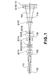
- Figure 1 illustrates the re-imaging optical system of this embodiment as being placed in the state in which the range of illumination upon the image plane becomes largest, that is, the state of largest ⁇ .
- the re-imaging optical system comprises a first lens group consisting of a plane parallel plate G111 and two convex lenses G112 and G113, a second lens group consisting of a single concave lens G114 only, a third lens group consisting of convex lenses G115 and G116, and a fourth lens group consisting of a single convex lens 118 disposed after a concave lens G117.
- There is a light path bending portion 114 provided between the concave lens G117 and the convex lens G118.
- the power of the first lens group and the spacing between principal points of the first and second lens groups are determined so that the point of intersection between the optical axis 115 and the principal ray of abaxial light is defined between the concave lens G114 and the convex lens G115.
- the position (light re-collecting position 116) where light from the secondary light source position 113 is re-collected and the light energy density becomes largest can be present between the concave lens G114 and the convex lens G115 in the largest ⁇ state.
- variable-magnification positions are provided as shown in Figure 2 while taking the second lens group comprising concave lens G114 as a first movable group and taking the third lens group comprising convex lenses G115 and G116 as a second movable group.
- the illumination range on the image plane should be made small, that is, if ⁇ value is going to be made small, the first movable group is displaced toward the light entrance side, while on the other hand the second movable group is displaced toward the light exit side of the re-imaging optical system.
- a variable illumination range optical system can be accomplished by which the range of illumination on the image plane can be changed continuously with both the intersection point position 118 between the optical axis 115 and the principal ray 117 of abaxial light and the light re-collecting position 116 as well kept placed in a space between the concave lens G114 and the convex lens G115, while on the other hand the back focus position can be maintained at a level practically without any inconveniences.
- the smallest ⁇ position is illustrated as P1
- an intermediate ⁇ position is illustrated as P2
- the largest ⁇ position is illustrated as P3, respectively.
- the light re-collecting position 116 is defined out of any lens elements.
- the illumination zone where the energy density becomes largest can be kept out of any lens elements but can be held present in a space.
- an afocal optical system that comprises concave lens G117 and convex lens G118, disposed in an order from the light entrance side, is provided after the second movable group.
- the curvature of the surface at the light entrance side is made larger than the curvature of the surface at the light exit side and also that there is a concave lens G117 present which lens has a concave surface facing toward the light entrance side.
- Table 1 shows numerical values of the specification of the re-imaging optical system used in the first embodiment.
- P1 means the smallest ⁇ position
- P2 means the intermediate ⁇ position
- P3 means the largest ⁇ position
- F1 is the focal lengths of the first optical system at the respective ⁇ positions
- f1, f2, f3 and f4 are focal lengths of the first, second, third and fourth lens groups, respectively.
- d7 denotes the variable spacing between the fist lens group and the second lens group along the optical axis
- d9 denotes the variable spacing between the second lens group and the third lens group along the optical axis
- d3 denotes the variable spacing between the third lens group and the concave lens G117 along the optical axis.
- S1 denotes the light beam diameter upon a certain evaluation plane which is at a distance 67 mm from the last surface of the first optical system, as defined after the parallel light impinging on an aperture stop 119 having an opening diameter o 10 mm passes through the re-imaging optical system of this embodiment.
- H1, H2 and H3 each denotes the position of intersection point 118 between the optical axis 115 and the principal ray 117 of abaxial light at the respective ⁇ positions, and each represents the distance from the ninth surface which is the light exit side surface of the concave lens G114.
- L1, L2 and L3 each denotes the light re-collecting position 116 where, in the respective ⁇ position, light emitted from the secondary light source position 113 is re-collected. It corresponds to the distance from the ninth surface which is the light exit side surface of the concave lens G117, in a case where the length of the rod-like glass 111 is made equal to 450 mm and the distance from the secondary light source position 113 to the light entrance end of the rod-like glass 111 is made equal to 15 mm.
- r denotes the curvature radius of each surface (unit is mm); d denotes the spacing between adjacent surfaces (unit is mm); n is the refractive index of the medium with respect to the incident light (wavelength is 0.248 ⁇ m); and k denotes the lens number of the re-imaging optical system as seen in Figure 2.
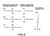
- Figure 3 is an aberration chart for explaining transverse aberration in meridional direction and transverse aberration in sagittal direction as well as distortion aberration of the re-imaging optical system used in the first embodiment, produced at the smallest ⁇ position P1 thereof.
- Figure 4 is an aberration chart for explaining transverse aberration in meridional direction and transverse aberration in sagittal direction as well as distortion aberration of the re-imaging optical system used in the first embodiment, produced at the largest ⁇ position P3 thereof. It is seen from these drawings that the distortion aberration is satisfactorily collected while the transverse aberrations are well suppressed within a practically allowable range.
- the fist moving group consists of a single concave lens, while the second moving group consists of two convex lenses.
- the point of intersection between the optical axis and the principal ray of abaxial light is placed between the first and second moving groups, and the moving group structure having been described with this embodiment is adopted.
- a continuously-variable illumination range optical system can be accomplished which enables: (i) the range of illumination with emitted light can be changed continuously even by use of a very simple magnification changing optical system having two moving groups; (ii) the telecentricity of emitted light can be maintained at a level free of any practical inconveniences, without stagnating the light re-collecting position inside any optical element; (iii) while on the other hand, transverse aberration can be well suppressed within a practically allowable range and, moreover, distortion aberration can be corrected satisfactorily.
- the re-imaging optical system according to the present embodiment can be incorporated into a step-and-repeat type projection exposure apparatus such as shown in Figure 15, for example, as a ⁇ continuously changing optical system, for example.
- a light source which comprises an excimer laser 1 having an emission wavelength 248 nm goes through a beam shaping optical system 2 by which it is transformed into a desired beam shape.
- the light is subsequently directed and projected onto a rod-like glass 111 having a hexagonal sectional shape, by means of a first relay optical system 3.
- the rod-like glass 111 has a function as plural-light-source forming means (integrator), and it serves to produce a plurality of light sources from a single light source on the basis of multiple reflections by the inner glass surfaces thereof. Light from this rod-like glass 111 is projected onto a fly's eye lens 112 by means of the ⁇ continuously changing optical system.
- the ⁇ continuously changing optical system is provided by a magnification changing optical system 4 having lenses G114 - G116 described with reference to the first embodiment, a concave lens G117, a mirror 5 for bending the optical axis 12 at a right angle within a sectional plane that contains the scan direction and the optical axis 12, and a convex lens G118.
- Light from the fly's eye lens 112 is directed to a mask 7 by a second relay optical system 6, so as to Koehler illuminate the mask 7 surface.
- Light passed through an opening of the mask 7 is directed to a reticle 9 (original) by means of a mask imaging optical system 8, to illuminate the reticle 9.
- the mask 7 and the reticle 9 are placed in an optically conjugate relationship.
- a circuit pattern formed on the reticle 9 is projected in a reduce scale onto a wafer 11 (substrate) surface having a photosensitive material applied thereto, by means of a projection optical system 10.
- a projection optical system which enables further extension of ⁇ -value variable range can be accomplished, without placing a light re-collecting position having a largest light energy density inside any lens elements, while on the other hand satisfying limitational conditions for structure and for optical materials by use of reduced number of lenses and with use of a simplified and compact structure.
- this embodiment is an example wherein a relay optical system having two convex lenses G121 and G122 as well as a re-imaging optical system having a function for imaging, upon an image plane, an object plane onto which light from the relay optical system is projected, are disposed between a first fly's eye lens 121 and a second fly's eye lens 122, in an order from the light entrance side thereof.
- This re-imaging optical system has a function for continuously changing the extension of illuminating range upon the image plane.
- the first and second fly's eye lenses 121 and 122 are placed approximately in a Fourier transform positional relationship with each other.
- the position where light from a light source which is defined at a light collecting position placed just after the first fly's eye lens 121, is the light re-collection position where the light energy becomes largest.
- the second embodiment is an example of re-imaging optical system which is arranged so that the light re-collecting position is defined out of any lens elements.
- Figure 5 illustrates the re-imaging optical system of this embodiment as being placed in the state in which the range of illumination upon_the image plane becomes largest, that is, the state of largest ⁇ .
- the re-imaging optical system comprises a first lens group consisting of two convex lenses G121 and G122, a second lens group consisting of a single concave lens G123 only, a third lens group consisting of convex lenses G124 and G125, and a fourth lens group consisting of a single convex lens 127 disposed after a concave lens G126.
- There is a light path bending portion 124 provided between the concave lens G126 and the convex lens G127.
- the power of the first lens group and the spacing between principal points of the first and second lens groups are determined so that the point of intersection between the optical axis 125 and the principal ray 127 of abaxial light is defined between the concave lens G123 and the convex lens G124.
- the light re-collecting position 126 where light from the light source defined at the light collecting position placed just after the first fly's eye lens 121 is re-collected and where the light energy density becomes largest can be present in registration with the intersection point position 128 between the optical axis 125 and the principal ray 127 of abaxial light, and it can be present between the concave lens G123 and the convex lens G124 in the largest ⁇ state.
- variable-magnification positions are provided as shown in Figure 6 while taking the second lens group comprising concave lens G123 as a first movable group and taking the third lens group comprising convex lenses G124 and G125 as a second movable group.
- the extension of illumination range on the image plane should be made small, that is, if ⁇ value is going to be made small, the second lens group is displaced toward the light entrance side, while on the other hand the third lens group is displaced toward the light exit side of the re-imaging optical system.
- a variable illumination range optical system can be accomplished by which the extension of illumination range on the image plane can be changed continuously, with the intersection point position 128 between the optical axis 125 and the principal ray 127 of abaxial light, that is, the light re-collecting position being kept placed in a space between the concave lens G123 and the convex lens G124, while on the other hand the back focus position can be maintained at a level practically without any inconveniences.
- the smallest ⁇ position is illustrated as P1
- an intermediate ⁇ position is illustrated as P2
- the largest ⁇ position is illustrated as P3, respectively.
- an afocal optical system that comprises concave lens G126 and convex lens G127, disposed in an order from the light entrance side, is provided after the second movable group.
- the curvature of the surface at the light entrance side is made larger than the curvature of the surface at the light exit side and also that there is a concave lens G126 present which lens has a concave surface facing toward the light entrance side.
- Table 2 shows numerical values of the specification of the re-imaging optical system used in the second embodiment.
- P1 means the smallest ⁇ position
- P2 means the intermediate ⁇ position
- P3 means the largest ⁇ position
- F1 is the focal lengths of a combined optical system provided by a relay optical system and the re-imaging optical system of the present embodiment, corresponding to respective ⁇ positions.
- fL1 is the focal length of the relay optical system
- f1, f2, f3 and f4 are focal lengths of the first, second, third and fourth lens groups, respectively.
- d9 denotes the variable spacing between the fist lens group and the second lens group along the optical axis
- d11 denotes the variable spacing between the second lens group and the third lens group along the optical axis
- d15 denotes the variable spacing between the third lens group and the concave lens G126 along the optical axis.
- S1 denotes the light beam diameter upon a certain evaluation plane which is at a distance of 69.5 mm from the last surface of the re-imaging optical system, as defined after a divergent light beam having NA of 0.1, that is, having a half size of largest angle being equal to 5.7 deg., emerging from the optical axis center of an aperture stop 129 having an opening diameter 12 mm, entered the re-imaging optical system of this embodiment.
- H1, H2 and H3 each denotes the position of intersection point 128 between the optical axis 125 and the principal ray 127 of abaxial light at the respective ⁇ positions, and each represents the distance from the eleventh surface which is the light exit side surface of the concave lens G123.
- L1, L2 and L3 each denotes the light re-collecting position 126 where, in the respective ⁇ position, light having been emitted from the light source defined by collected light just after being emitted from the first fly's eye lens 121 and having entered the re-imaging optical system of this embodiment is re-collected. It corresponds to the distance from the eleventh surface which is the light exit side surface of the concave lens G123.
- r denotes the curvature radius of each surface (unit is mm); d denotes the spacing between adjacent surfaces (unit is mm); n is the refractive index of the medium with respect to the incident light (wavelength is 0.193 ⁇ m); and k denotes the lens number of the re-imaging optical system as seen in Figure 6.
- Figure 7 is an aberration chart for explaining transverse aberration in meridional direction and transverse aberration in sagittal direction as well as distortion aberration of the combined optical system of the relay optical system and the re-imaging optical system used in the second embodiment, being produced at the smallest ⁇ position P1 thereof.
- Figure 8 is an aberration chart for explaining transverse aberration in meridional direction and transverse aberration in sagittal direction as well as distortion aberration of the combined optical system used in the second embodiment, produced at the largest ⁇ position P3 thereof. It is seen from these drawings that the distortion aberration is satisfactorily collected while the transverse aberrations are well suppressed within a practically allowable range.
- the fist moving group consists of a single concave lens, while the second moving group consists of two convex lenses.
- the point of intersection between the optical axis and the principal ray of abaxial light is placed between the first and second moving groups, and the moving group structure having been described with this embodiment is adopted.
- a continuously-variable illumination range optical system can be accomplished which enables: (i) the range of illumination with emitted light can be changed continuously even by use of a very simple magnification changing optical system having two moving groups; (ii) the telecentricity of emitted light can be maintained at a level free of any practical inconveniences, without stagnating the light re-collecting position inside any optical element; (iii) while on the other hand, transverse aberration can be well suppressed within a practically allowable range and, moreover, distortion aberration can be corrected satisfactorily.
- the re-imaging optical system according to the present embodiment can be incorporated into a step-and-scan type projection such as shown in Figure 16, for example, as a ⁇ continuously changing optical system, for example.
- a light source which comprises an excimer laser 1 having an emission wavelength 193 nm, for example, goes through a beam shaping optical system 22 by which it is transformed into a desired beam shape.
- the light is subsequently directed and projected onto a first fly's eye lens 121 having a function as plural-light-source forming means.
- the relay optical system 24 is provided by lenses LG121 and LG122 having been described with reference to the present embodiment.
- the ⁇ continuously changing optical system is provided by a magnification changing optical system 25 having lenses G121 - G125 described with reference to the present embodiment, a concave lens G126, a mirror 26 for bending the optical axis 33 at a right angle within a sectional plane that contains the scan direction and the optical axis 33, and a convex lens G127.
- Light from the fly's eye lens 122 is directed to a mask 28 by a second relay optical system 27, so as to Koehler illuminate the mask 28 surface.
- Light passed through the mask 28 is directed to a reticle 30 (original) by means of a mask imaging optical system 29, to illuminate the reticle 30.
- the mask 28 and the reticle 30 are placed in an optically conjugate relationship.
- a circuit pattern formed on the reticle 30 is projected in a reduce scale onto a wafer 31 (substrate) surface having a photosensitive material applied thereto, by means of a projection optical system 31.
- a projection optical system which enables further extension of ⁇ -value variable range can be accomplished, without placing a light re-collecting position having a largest light energy density inside any lens elements, while on the other hand satisfying limitational conditions for structure and for optical materials by use of reduced number of lenses and with use of a simplified and compact structure.
- this embodiment is an example wherein a relay optical system 134 for illuminating a mask 139 surface with light from a fly's eye lens 131 (plural-light-source forming means) as well as a re-imaging optical system for illuminating a reticle (original) 132 surface with light from the mask 139 surface, are disposed between the first fly's eye lens 131 and the reticle 132.
- the mask 139 surface and the pattern bearing surface of the reticle 132 are placed in an imaging relationship with each other.
- the third embodiment is an example of re-imaging optical system which is arranged so that the light re-collecting position is defined out of any lens elements.
- Figure 9 illustrates the relay optical system 134 and the re-imaging optical system of this embodiment.
- the relay optical system 134 comprises a plurality of lens groups and it is an optical system having a function for collecting parallel light incident thereon, adjacent the mask 139 surface.
- the exit pupil position thereof is placed coincident with the entrance pupil position of the re-imaging optical system which is disposed after the relay optical system.
- the re-imaging optical system of this embodiment comprises, in an order from the light entrance side thereof, a cover glass CG131, a first lens group consisting of a concave lens G131 and three convex lenses G132, G133 and G134, a second lens group consisting of a single concave lens G135 only, a third lens group consisting of a single convex lens G136 only, and a fourth lens group consisting of a convex lens G137, a concave lens G138 and a convex lens G139.
- a reticle cover glass CG133 for protection against particles.
- the power of the first lens group and the spacing between principal points of the first and second lens groups are determined so that the position 138 of intersection point between the optical axis 135 and the principal ray 137 of abaxial light is defined between the concave lens G135 and the convex lens G136.
- the light re-collecting position where light from the light source defined at the light collecting position placed just after the fly's eye lens 131 is re-collected and where the light energy density becomes largest can be present in registration with the intersection point position 138 between the optical axis 135 and the principal ray 137 of abaxial light, and it can be present between the concave lens G135 and the convex lens G136. In other words, it is assured that the illumination zone where the energy density becomes largest is prevented from being present inside any lens elements.
- an optical system of triplet type constituted by convex lens G137, concave lens 138 and convex lens G139 in an order from the light entrance side, is provided as the fourth lens group.
- Figure 10 illustrates transverse aberration in meridional direction and transverse aberration in sagittal direction as well as distortion aberration and exit side telecentricity of the re-imaging optical system of the third embodiment, wherein incidence NA is 0.3 and the reticle side largest image height is 57 mm. It is seen from this drawing that transverse aberration is well suppressed within a practically allowable range, while distortion aberration is corrected satisfactorily.
- the imaging magnification that is, the ratio of the extension of the illumination range on the pattern surface of the reticle 132 to the extension of the illumination range on the mask 139 surface
- the imaging magnification is equal to -1.3x. Making the magnification smaller beyond this value is undesirable because required increases in size of the mask mechanism would cause degradation of the masking precision.
- the re-imaging optical system should desirably have an imaging magnification having an absolute value B M which is not less than 1.3.
- Table 3 shows numerical values of the specification of the re-imaging optical system used in the third embodiment.
- f1, f2, f3 and f4 are focal lengths of the first, second, third and fourth lens groups, respectively.
- T and P denotes the object-to-image distance and the entrance pupil distance, respectively, described hereinbefore.
- H denotes the position 138 of intersection point between the optical axis 135 and the principal ray 137 of abaxial light, and it corresponds to the distance from the twelfth surface which is the light exit side surface of the concave lens G135.
- r denotes the curvature radius of each surface (unit is mm); d denotes the spacing between adjacent surfaces (unit is mm); n is the refractive index of the medium with respect to the incident light (wavelength is 0.193 ⁇ m); and k denotes the lens number of the re-imaging optical system as seen in Figure 9.
- the point of intersection between the optical axis and the principal ray of abaxial light is placed between a concave lens and a convex lens, and with this arrangement, a re-imaging optical system can be accomplished which enables: (i) the light re-collecting position can be prevented from being defined inside any optical elements yet an optical system having a small number of lens elements is used; (ii) transverse aberration can be well suppressed within a practically allowable range and, moreover, distortion aberration can be corrected satisfactorily; and (iii) the telecentricity of emitted light can be maintained at a level free of any practical inconveniences.
- the re-imaging optical system according to the present embodiment can be incorporated into a step-and-scan type projection exposure apparatus such as shown in Figure 17, for example, as a mask imaging optical system, for example.
- a light source which comprises an excimer laser 41 having an emission wavelength 193 nm goes through a beam shaping optical system 42 by which it is transformed into a desired beam shape.
- the light is subsequently directed and projected onto a rod-like glass 44 having a hexagonal sectional shape, by means of a relay optical system 43.
- the rod-like glass 44 serves to produce a plurality of light sources from a single light source on the basis of multiple reflections by the inner glass surfaces thereof. Light from this rod-like glass 44 is projected onto a fly's eye lens 131 by means of a ⁇ continuously changing optical system 45.
- Light from the fly's eye lens 131 is directed to a mask 139 surface by a second relay optical system 134, so as to Koehler illuminate the mask 139 surface.
- Light passed through the mask 139 is directed to a reticle 49 by means of a mask imaging optical system (46, 47, 48) to illuminate the reticle 49.
- the mask 139 and the reticle 49 are placed in an imaging relationship with each other.
- a circuit pattern formed on the reticle 49 is projected in a reduce scale onto a wafer 51 (substrate) surface having a photosensitive material applied thereto, by means of a projection optical system 50.
- the mask imaging optical system described above can be replaced by a re-imaging optical system described with reference to the present embodiment.
- the mask imaging optical system comprises a first light collecting optical system 46 consisting of a cover glass CG131 and lens groups G131 - G135, a mirror 47 for bending the optical axis 52 at a right angle within a sectional plane that contains the scan direction and the optical axis 52, and a second light collecting optical system comprising an optical system of triplet structure, consisting of a convex lens G137, a concave lens G138 and a convex lens G139 and a cover glass CG132.
- the entrance NA of the re-imaging optical system of this embodiment is 0.3 and the imaging magnification is -1.3x, it is possible to use such a projection optical system 50 by which the imaging magnification with respect to the reticle surface vs. wafer substrate surface is made equal to -0.25 and the wafer side imaging numerical aperture NA is made equal to 0.92.
- an illumination optical system and a projection exposure apparatus that enables further enlargement of NA of the projection optical system while satisfying limitational conditions for structure and for optical materials, can be accomplished by use of a reduced number of lenses and with use of a simplified and compact structure, and without placing the light re-collecting position, where the light energy density becomes largest, inside any optical elements.
- this embodiment is an example wherein a relay optical system 144 for illuminating a mask 149 surface with light from a fly's eye lens 141 (plural-light-source forming means) as well as a re-imaging optical system for illuminating a reticle (original) 142 surface with light from the mask 149 surface, are disposed between the first fly's eye lens 141 and the reticle 142.
- the mask 149 surface and the reticle 142 are placed in an imaging relationship with each other.
- the fourth embodiment is an example of re-imaging optical system which is arranged so that the light re-collecting position is defined out of any lens elements.
- the re-imaging optical system of this embodiment has an imaging magnification of -1.6x.
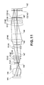
- FIG 11 illustrates the relay optical system 144 and the re-imaging optical system of this embodiment.
- the relay optical system 144 has a similar structure as of the third embodiment, and it comprises a plurality of lens groups. It is an optical system having a function for collecting parallel light incident thereon, adjacent the mask 149 surface. The exit pupil position thereof is placed coincident with the entrance pupil position of the re-imaging optical system which is disposed after the relay optical system.
- the re-imaging optical system of this embodiment comprises, in an order from the light entrance side thereof, a cover glass CG141, a first lens group consisting of a concave lens G141 and three convex lenses G142, G143 and G144, a second lens group consisting of a single concave lens G145 only, a third lens group consisting of a single convex lens G146 only, and a fourth lens group consisting of a convex lens G147, a concave lens G148 and a convex lens G149.
- There is a light path bending portion 144 provided between the third and fourth lens groups, to bend the optical axis 145 at a right angle.
- a reticle cover glass CG143 for protection against particles.
- the power of the first lens group and the spacing between principal points of the first and second lens groups are determined so that the position 148 of intersection point between the optical axis 145 and the principal ray 147 of abaxial light is defined between the second lens group G145 and the third lens group G146.
- the light re-collecting position where light from the light source defined at the light collecting position placed just after the fly's eye lens 141 is re-collected and where the light energy density becomes largest can be present in registration with the intersection point position 148 between the optical axis 145 and the principal ray 147 of abaxial light, and it can be present between the concave lens G145 and the convex lens G146. In other words, it is assured that the illumination zone where the energy density becomes largest is prevented from being present inside any lens elements.
- an optical system of triplet type is provided as the fourth lens group. Namely, by disposing convex lens G147, concave lens G148 and convex lens G149 in an order from the light entrance side, distortion aberration as well as parallelism, with respect to the optical axis, of the principal ray of abaxial light toward the reticle 142, that is, the telecentricity, can be maintained at a satisfactory level.
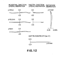
- Figure 12 illustrates transverse aberration in meridional direction and transverse aberration in sagittal direction as well as distortion aberration and exit side telecentricity of the re-imaging optical system of the fourth embodiment, wherein incidence NA is 0.38 and the reticle side largest image height is 57 mm. It is seen from this drawing that transverse aberration is well suppressed within a practically allowable range, while distortion aberration is corrected satisfactorily.
- Table 4 shows numerical values of the specification of the re-imaging optical system used in the fourth embodiment.
- f1, f2, f3 and f4 are focal lengths of the first, second, third and fourth lens groups, respectively.
- T and P denotes the object-to-image distance and the entrance pupil distance, respectively, described hereinbefore.
- H denotes the position 148 of intersection point between the optical axis 145 and the principal ray 147 of abaxial light, and it corresponds to the distance from the twelfth surface which is the light exit side surface of the concave lens G145.
- r denotes the curvature radius of each surface (unit is mm); d denotes the spacing between adjacent surfaces (unit is mm); n is the refractive index of the medium with respect to the incident light (wavelength is 0.193 ⁇ m); and k denotes the lens number of the re-imaging optical system as seen in Figure 11.
- Equation (1) The coefficients regarding the aspherical surface as shown in Table 4 can be expressed by equation (1) below, when the height of an arbitrary point on the aspherical surface with respect to a direction perpendicular to the optical axis is denoted by h, the distance along the optical axis is denoted by x, the curvature radius at the vertex is r, and the curved surface coefficient is denoted by K, and where the aspherical coefficients are denoted by alphabets A to F, respectively.
- x h 2 /r/ [1+ ⁇ 1- (1+K) (h/r) 2 ⁇ 1/2 ] +Ah 4 +Bh 6 +Ch 8 +Dh 10 +Eh 12 +Fh 14
- the point of intersection between the optical axis and the principal ray of abaxial light is placed between a concave lens and a convex lens, and with this arrangement, a re-imaging optical system can be accomplished which enables: (i) the light re-collecting position can be prevented from being defined inside any optical elements yet an optical system having a small number of lens elements is used; (ii) transverse aberration can be well suppressed within a practically allowable range and, moreover, distortion aberration can be corrected satisfactorily; and (iii) the distortion aberration and the exit side telecentricity can be maintained at a level free of any practical inconveniences.
- the re-imaging optical system according to the present embodiment can be incorporated into a projection exposure apparatus such as shown in Figure 17, for example, to be substituted for a mask imaging optical system that comprises a first light collecting optical system 46, a mirror 46, and a second light collecting optical system 48.
- the imaging side numerical aperture NA W of the projection optical system should desirably be not greater than 0.95.
- an illumination optical system and a projection exposure apparatus that enables further enlargement of NA of the projection optical system while satisfying limitational conditions for structure and for optical materials, can be accomplished by use of a reduced number of lenses and with use of a simplified and compact structure, and without placing the light re-collecting position, where the light energy density becomes largest, inside any optical elements.
- this embodiment is an example wherein a relay optical system 154 for illuminating a mask 159 surface as well as a re-imaging optical system for illuminating the pattern bearing surface of a reticle (original) 152 with light from the mask 159 surface, are disposed between a fly's eye lens 151 and the reticle 152.
- the mask 159 surface and the reticle 152 are placed in an imaging relationship with each other.
- the position where light from a light source which is defined at a light collecting position placed just after the fly's eye lens 151, is the light re-collection position where the light energy becomes largest.
- the fifth embodiment is an example of re-imaging optical system which is arranged so that the light re-collecting position is defined out of any lens elements.
- the re-imaging optical system of this embodiment has an imaging magnification of -2.0x.
- the third embodiment uses an excimer laser having an emission wavelength of 0.193 ⁇ m as a light source
- this embodiment uses an excimer laser having an emission wavelength of 0.248 ⁇ m as a light source.
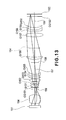
- Figure 13 illustrates the relay optical system 154 and the re-imaging optical system of this embodiment.
- the relay optical system 154 has a similar structure as of the third embodiment, and it comprises a plurality of lens groups. It is an optical system having a function for collecting parallel light incident thereon, adjacent the mask 159 surface. The exit pupil position thereof is placed coincident with the entrance pupil position of the re-imaging optical system which is disposed after the relay optical system.
- the re-imaging optical system of this embodiment comprises, in an order from the light entrance side thereof, a cover glass CG151, a first lens group consisting of a concave lens G151 and three convex lenses G152, G153 and G154, a second lens group consisting of a single concave lens G155 only, a third lens group consisting of a single convex lens G156 only, and a fourth lens group consisting of a convex lens G157, a concave lens G158 and a convex lens G159.
- There is a light path bending portion 154 provided between the third and fourth lens groups, to bend the optical axis 135 at a right angle.
- a reticle cover glass CG153 for protection against particles.
- the power of the first lens group and the spacing between principal points of the first and second lens groups are determined so that the position 158 of intersection point between the optical axis 155 and the principal ray 157 of abaxial light is defined between the second lens group G155 and the third lens group G156.
- the light re-collecting position where light from the light source defined at the light collecting position placed just after the fly's eye lens 151 is re-collected and where the light energy density becomes largest can be present in registration with the intersection point position 158 between the optical axis 155 and the principal ray 157 of abaxial light, and it can be present between the concave lens G155 and the convex lens G156. In other words, it is assured that the illumination zone where the energy density becomes largest is prevented from being present inside any lens elements.
- an optical system of triplet type is provided as the fourth lens group. Namely, by disposing convex lens G157, concave lens G158 and convex lens G159 in an order from the light entrance side, distortion aberration as well as parallelism, with respect to the optical axis, of the principal ray of abaxial light toward the reticle 152, that is, the telecentricity, can be maintained at a satisfactory level.
- Figure 14 illustrates transverse aberration in meridional direction and transverse aberration in sagittal direction as well as distortion aberration and exit side telecentricity of the re-imaging optical system of the fifth embodiment, wherein incidence NA is 0.4 and the reticle side largest image height is 57 mm. It is seen from this drawing that transverse aberration is well suppressed within a practically allowable range, while distortion aberration is corrected satisfactorily.
- the imaging magnification that is, the ratio of the extension of the illumination range on the pattern surface of the reticle 152 to the extension of the illumination range on the mask 159 surface
- the absolute value of this imaging magnification goes beyond 2.5, it may disadvantageously cause an increase in size of the relay optical system 154 or degradation of performance.
- the re-imaging optical system should desirably have an imaging magnification having an absolute value B M which is not greater than 2.5.
- Table 5 shows numerical values of the specification of the re-imaging optical system used in the fifth embodiment.
- f1, f2, f3 and f4 are focal lengths of the first, second, third and fourth lens groups, respectively.
- T and P denotes the object-to-image distance and the entrance pupil distance, respectively, described hereinbefore.
- H denotes the position 158 of intersection point between the optical axis 155 and the principal ray 157 of abaxial light, and it corresponds to the distance from the twelfth surface which is the light exit side surface of the concave lens G155.
- r denotes the curvature radius of each surface (unit is mm); d denotes the spacing between adjacent surfaces (unit is mm); n is the refractive index of the medium with respect to the incident light (wavelength is 0.193 ⁇ m); and k denotes the lens number of the re-imaging optical system as seen in Figure 13.
- the point of intersection between the optical axis and the principal ray of abaxial light is placed between a concave lens and a convex lens, and with this arrangement, a re-imaging optical system can be accomplished which enables: (i) the light re-collecting position can be prevented from being defined inside any optical elements yet an optical system having a small number of lens elements is used; (ii) transverse aberration can be well suppressed within a practically allowable range and, moreover, distortion aberration can be corrected satisfactorily; and (iii) the distortion aberration and the exit side telecentricity can be maintained at a level free of any practical inconveniences.
- the re-imaging optical system according to the present embodiment can be incorporated into a projection exposure apparatus such as shown in Figure 17, for example, to be substituted for a mask imaging optical system that comprises a first light collecting optical system 46, a mirror 47, and a second light collecting optical system 48.
- the entrance NA of the re-imaging optical system of this embodiment is 0.4 and the imaging magnification is -2.0x, it is possible to use such a projection optical system by which the imaging magnification with respect to the reticle surface vs. wafer substrate surface is made equal to -0.25 and the wafer side imaging numerical aperture NA is made equal to 0.8.
- the re-imaging optical system of this embodiment is particularly effective where it is used with a projection optical system having an image side numerical aperture NA not less than 0.7.
- an illumination optical system and a projection exposure apparatus that enables further enlargement of NA of the projection optical system while satisfying limitational conditions for structure and for optical materials, can be accomplished by use of a reduced number of lenses and with use of a simplified and compact structure, and without placing the light re-collecting position, where the light energy density becomes largest, inside any optical elements.
- the light re-collecting position that is, the position where the light energy density becomes very large, can be assuredly prevented from being placed inside any optical elements.
- This is very advantageous because it avoids degradation of internal transmittance of an optical material used as a lens material, or degradation of anti-reflection film applied to the lens surface.
- the throughput of the exposure apparatus can be improved, while suppressing deterioration of illuminance of the illumination optical system.
- the second advantageous feature is that the first advantageous feature itself can be realized by use of a very simple optical system. This means that, in regard to the ⁇ value of the projection optical system or the numerical aperture NA thereof, a much wide illumination state can be accomplished while keeping the cost and apparatus size as before. Hence, in the semiconductor device manufacturing process, a large variety of circuit patterns can be printed.
- the plural light source forming means usable in the present invention may include a lens array having a plurality of lenses arrayed two-dimensionally (e.g., fly's eye lens or micro-lens array), a glass rod or a hollow rod having mirror surface defined on the inner surface thereof.
- a lens array having a plurality of lenses arrayed two-dimensionally (e.g., fly's eye lens or micro-lens array), a glass rod or a hollow rod having mirror surface defined on the inner surface thereof.
- it may include an integrator comprising a pair of cylindrical lens plates (or lenticular lenses) being piled.
- Step 18 is a flow chart for explaining the procedure of manufacturing various microdevices such as semiconductor chips (e.g., ICs or LSIs), liquid crystal panels, or CCDs, for example.
- Step 1 is a design process for designing a circuit of a semiconductor device.
- Step 2 is a process for making a mask on the basis of the circuit pattern design.
- Step 3 is a process for preparing a wafer by using a material such as silicon.
- Step 4 is a wafer process which is called a pre-process wherein, by using the thus prepared mask and wafer, a circuit is formed on the wafer in practice, in accordance with lithography.
- Step 5 subsequent to this is an assembling step which is called a post-process wherein the wafer having been processed at step 4 is formed into semiconductor chips.
- This step includes an assembling (dicing and bonding) process and a packaging (chip sealing) process.
- Step 6 is an inspection step wherein an operation check, a durability check an so on, for the semiconductor devices produced by step 5, are carried out. With these processes, semiconductor devices are produced, and they are shipped (step 7).
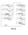
- Step 19 is a flow chart for explaining details of the wafer process included in the procedure described above.
- Step 11 is an oxidation process for oxidizing the surface of a wafer.
- Step 12 is a CVD process for forming an insulating film on the wafer surface.
- Step 13 is an electrode forming process for forming electrodes upon the wafer by vapor deposition.
- Step 14 is an ion implanting process for implanting ions to the wafer.
- Step 15 is a resist process for applying a resist (photosensitive material) to the wafer.
- Step 16 is an exposure process for printing, by exposure, the circuit pattern of the mask on the wafer through the exposure apparatus described above.
- Step 17 is a developing process for developing the exposed wafer.
- Step 18 is an etching process for removing portions other than the developed resist image.
- Step 19 is a resist separation process for separating the resist material remaining on the wafer after being subjected to the etching process. By repeating these processes, circuit patterns are superposedly formed on
Landscapes
- Physics & Mathematics (AREA)
- General Physics & Mathematics (AREA)
- Lenses (AREA)
- Exposure And Positioning Against Photoresist Photosensitive Materials (AREA)
- Exposure Of Semiconductors, Excluding Electron Or Ion Beam Exposure (AREA)
- Microscoopes, Condenser (AREA)
Applications Claiming Priority (2)
| Application Number | Priority Date | Filing Date | Title |
|---|---|---|---|
| JP2004119249A JP2005301054A (ja) | 2004-04-14 | 2004-04-14 | 照明光学系及びそれを用いた露光装置 |
| JP2004119249 | 2004-04-14 |
Publications (2)
| Publication Number | Publication Date |
|---|---|
| EP1586950A2 true EP1586950A2 (fr) | 2005-10-19 |
| EP1586950A3 EP1586950A3 (fr) | 2007-02-28 |
Family
ID=34940803
Family Applications (1)
| Application Number | Title | Priority Date | Filing Date |
|---|---|---|---|
| EP05252302A Withdrawn EP1586950A3 (fr) | 2004-04-14 | 2005-04-13 | Système d'illumination optique, appareil d'exposition et méthode de fabrication d'un dispositif |
Country Status (3)
| Country | Link |
|---|---|
| US (1) | US7170686B2 (fr) |
| EP (1) | EP1586950A3 (fr) |
| JP (1) | JP2005301054A (fr) |
Families Citing this family (8)
| Publication number | Priority date | Publication date | Assignee | Title |
|---|---|---|---|---|
| EP1927890A1 (fr) | 2006-11-30 | 2008-06-04 | Carl Zeiss SMT AG | Procédé de fabrication d'un objectif de projection et objectif de projection fabriqué selon ce procédé |
| JP5559543B2 (ja) * | 2006-11-30 | 2014-07-23 | カール・ツァイス・エスエムティー・ゲーエムベーハー | 投影対物器械を製造する方法及びこの方法によって製造される投影対物器械 |
| CN100526832C (zh) * | 2006-12-14 | 2009-08-12 | 中国科学院长春光学精密机械与物理研究所 | 离轴反射光学镜头焦距的检验方法 |
| TWI467224B (zh) * | 2012-11-21 | 2015-01-01 | Largan Precision Co Ltd | 光學拾像鏡片系統 |
| US10031405B2 (en) | 2014-06-12 | 2018-07-24 | Nec Display Solutions, Ltd. | Light source device and projector with reducing optical system having adjustable position for positive power lens |
| US10761313B2 (en) | 2014-08-29 | 2020-09-01 | Canon Kabushiki Kaisha | Eyepiece lens, observation apparatus, and imaging apparatus including the same |
| WO2023283871A1 (fr) * | 2021-07-15 | 2023-01-19 | 欧菲光集团股份有限公司 | Système optique, module de capture d'image et dispositif électronique |
| CN116858504B (zh) * | 2023-09-04 | 2023-12-08 | 武汉振光科技有限公司 | 光轴监测系统 |
Family Cites Families (7)
| Publication number | Priority date | Publication date | Assignee | Title |
|---|---|---|---|---|
| DE19548805A1 (de) | 1995-12-27 | 1997-07-03 | Zeiss Carl Fa | REMA-Objektiv für Mikrolithographie-Projektionsbelichtungsanlagen |
| JP2001228401A (ja) * | 2000-02-16 | 2001-08-24 | Canon Inc | 投影光学系、および該投影光学系による投影露光装置、デバイス製造方法 |
| JP2002055277A (ja) | 2000-08-11 | 2002-02-20 | Nikon Corp | リレー結像光学系、および該光学系を備えた照明光学装置並びに露光装置 |
| JP2002090654A (ja) * | 2000-09-12 | 2002-03-27 | Olympus Optical Co Ltd | 投影光学系を有する中間鏡筒及び投影光学系を有する顕微鏡 |
| JP3673731B2 (ja) | 2001-05-22 | 2005-07-20 | キヤノン株式会社 | 露光装置及び方法 |
| DE10144244A1 (de) * | 2001-09-05 | 2003-03-20 | Zeiss Carl | Zoom-System, insbesondere für eine Beleuchtungseinrichtung |
| JP3950731B2 (ja) | 2002-04-23 | 2007-08-01 | キヤノン株式会社 | 照明光学系、当該照明光学系を有する露光装置及びデバイス製造方法 |
-
2004
- 2004-04-14 JP JP2004119249A patent/JP2005301054A/ja not_active Withdrawn
-
2005
- 2005-04-13 EP EP05252302A patent/EP1586950A3/fr not_active Withdrawn
- 2005-04-13 US US11/105,866 patent/US7170686B2/en not_active Expired - Fee Related
Also Published As
| Publication number | Publication date |
|---|---|
| US7170686B2 (en) | 2007-01-30 |
| EP1586950A3 (fr) | 2007-02-28 |
| US20050230599A1 (en) | 2005-10-20 |
| JP2005301054A (ja) | 2005-10-27 |
Similar Documents
| Publication | Publication Date | Title |
|---|---|---|
| KR101532824B1 (ko) | 노광 방법 및 장치, 그리고 디바이스 제조 방법 | |
| EP1367442A2 (fr) | Dispositif d'illumination | |
| KR20000011933A (ko) | 카타다이옵트릭광학시스템및그를구비한노광장치 | |
| KR100506497B1 (ko) | 조명장치, 그것을 이용한 노광장치 및 디바이스 제조방법 | |
| CN101006552A (zh) | 光学照明装置、光学照明装置的调整方法、曝光装置以及曝光方法 | |
| JP2001141995A (ja) | 光学的投影レンズ系 | |
| EP0811865B1 (fr) | Système d'illumination et appareil d'exposition | |
| US7403262B2 (en) | Projection optical system and exposure apparatus having the same | |
| JP2004022708A (ja) | 結像光学系、照明光学系、露光装置及び露光方法 | |
| EP0863440B1 (fr) | Appareil d'exposition par projection et méthode de fabrication d'un dispositif | |
| US7170686B2 (en) | Illumination optical system, exposure apparatus, and device manufacturing method using the same | |
| US6459534B1 (en) | Projection optical system and projection exposure apparatus with the same, and device manufacturing method | |
| KR20020046932A (ko) | 콘덴서 광학계, 및 그 광학계를 구비한 조명 광학 장치그리고 노광 장치 | |
| US6924937B2 (en) | Aberration correcting optical system | |
| US20030210385A1 (en) | Projection optical system, a projection exposure apparatus provided with the same, as well as a device manufacturing method | |
| KR100675736B1 (ko) | 조명광학계 및 그것을 가진 노광장치 | |
| US6621555B1 (en) | Projection optical system and projection exposure apparatus with the same, and device manufacturing method | |
| JP2002055277A (ja) | リレー結像光学系、および該光学系を備えた照明光学装置並びに露光装置 | |
| US20060197933A1 (en) | Exposure apparatus | |
| US7242457B2 (en) | Exposure apparatus and exposure method, and device manufacturing method using the same | |
| US8436980B2 (en) | Illumination optical apparatus, relay optical system, exposure apparatus, and device manufacturing method | |
| JPH11307443A (ja) | 投影露光装置及びそれを用いたデバイスの製造方法 |
Legal Events
| Date | Code | Title | Description |
|---|---|---|---|
| PUAI | Public reference made under article 153(3) epc to a published international application that has entered the european phase |
Free format text: ORIGINAL CODE: 0009012 |
|
| AK | Designated contracting states |
Kind code of ref document: A2 Designated state(s): AT BE BG CH CY CZ DE DK EE ES FI FR GB GR HU IE IS IT LI LT LU MC NL PL PT RO SE SI SK TR |
|
| AX | Request for extension of the european patent |
Extension state: AL BA HR LV MK YU |
|
| PUAL | Search report despatched |
Free format text: ORIGINAL CODE: 0009013 |
|
| AK | Designated contracting states |
Kind code of ref document: A3 Designated state(s): AT BE BG CH CY CZ DE DK EE ES FI FR GB GR HU IE IS IT LI LT LU MC NL PL PT RO SE SI SK TR |
|
| AX | Request for extension of the european patent |
Extension state: AL BA HR LV MK YU |
|
| 17P | Request for examination filed |
Effective date: 20070828 |
|
| AKX | Designation fees paid |
Designated state(s): DE GB NL |
|
| 17Q | First examination report despatched |
Effective date: 20071009 |
|
| STAA | Information on the status of an ep patent application or granted ep patent |
Free format text: STATUS: THE APPLICATION HAS BEEN WITHDRAWN |
|
| 18W | Application withdrawn |
Effective date: 20071214 |
|
| P01 | Opt-out of the competence of the unified patent court (upc) registered |
Effective date: 20230522 |