EP1588086B1 - Pressfitting - Google Patents
Pressfitting Download PDFInfo
- Publication number
- EP1588086B1 EP1588086B1 EP03788840A EP03788840A EP1588086B1 EP 1588086 B1 EP1588086 B1 EP 1588086B1 EP 03788840 A EP03788840 A EP 03788840A EP 03788840 A EP03788840 A EP 03788840A EP 1588086 B1 EP1588086 B1 EP 1588086B1
- Authority
- EP
- European Patent Office
- Prior art keywords
- sealing element
- press fitting
- section
- channels
- cross
- Prior art date
- Legal status (The legal status is an assumption and is not a legal conclusion. Google has not performed a legal analysis and makes no representation as to the accuracy of the status listed.)
- Expired - Lifetime
Links
- 238000007789 sealing Methods 0.000 claims abstract description 95
- 239000011324 bead Substances 0.000 claims abstract description 17
- 230000005484 gravity Effects 0.000 claims description 3
- 230000015572 biosynthetic process Effects 0.000 abstract description 2
- 230000006835 compression Effects 0.000 abstract description 2
- 238000007906 compression Methods 0.000 abstract description 2
- 238000004519 manufacturing process Methods 0.000 description 5
- 230000008719 thickening Effects 0.000 description 4
- 238000012360 testing method Methods 0.000 description 3
- 238000009825 accumulation Methods 0.000 description 2
- 238000005516 engineering process Methods 0.000 description 2
- 238000005553 drilling Methods 0.000 description 1
- 230000005489 elastic deformation Effects 0.000 description 1
- 239000013013 elastic material Substances 0.000 description 1
- 238000003780 insertion Methods 0.000 description 1
- 230000037431 insertion Effects 0.000 description 1
- 239000000463 material Substances 0.000 description 1
- 239000002184 metal Substances 0.000 description 1
- 230000035699 permeability Effects 0.000 description 1
- 230000035939 shock Effects 0.000 description 1
Images

Classifications
-
- F—MECHANICAL ENGINEERING; LIGHTING; HEATING; WEAPONS; BLASTING
- F16—ENGINEERING ELEMENTS AND UNITS; GENERAL MEASURES FOR PRODUCING AND MAINTAINING EFFECTIVE FUNCTIONING OF MACHINES OR INSTALLATIONS; THERMAL INSULATION IN GENERAL
- F16L—PIPES; JOINTS OR FITTINGS FOR PIPES; SUPPORTS FOR PIPES, CABLES OR PROTECTIVE TUBING; MEANS FOR THERMAL INSULATION IN GENERAL
- F16L13/00—Non-disconnectable pipe joints, e.g. soldered, adhesive, or caulked joints
- F16L13/14—Non-disconnectable pipe joints, e.g. soldered, adhesive, or caulked joints made by plastically deforming the material of the pipe, e.g. by flanging, rolling
- F16L13/141—Non-disconnectable pipe joints, e.g. soldered, adhesive, or caulked joints made by plastically deforming the material of the pipe, e.g. by flanging, rolling by crimping or rolling from the outside
- F16L13/142—Non-disconnectable pipe joints, e.g. soldered, adhesive, or caulked joints made by plastically deforming the material of the pipe, e.g. by flanging, rolling by crimping or rolling from the outside with a sealing element inserted into the female part before crimping or rolling
-
- F—MECHANICAL ENGINEERING; LIGHTING; HEATING; WEAPONS; BLASTING
- F16—ENGINEERING ELEMENTS AND UNITS; GENERAL MEASURES FOR PRODUCING AND MAINTAINING EFFECTIVE FUNCTIONING OF MACHINES OR INSTALLATIONS; THERMAL INSULATION IN GENERAL
- F16L—PIPES; JOINTS OR FITTINGS FOR PIPES; SUPPORTS FOR PIPES, CABLES OR PROTECTIVE TUBING; MEANS FOR THERMAL INSULATION IN GENERAL
- F16L13/00—Non-disconnectable pipe joints, e.g. soldered, adhesive, or caulked joints
- F16L13/14—Non-disconnectable pipe joints, e.g. soldered, adhesive, or caulked joints made by plastically deforming the material of the pipe, e.g. by flanging, rolling
- F16L13/148—Non-disconnectable pipe joints, e.g. soldered, adhesive, or caulked joints made by plastically deforming the material of the pipe, e.g. by flanging, rolling specially designed to ensure an intended leakage until correct deformation
Definitions
- the invention relates to a press fitting for producing an inseparably tight connection of blunt-end pipes, with at least one sleeve-like cross-section and at least one bead provided approximately at the end of the sleeve section, which receives at least one annular rubber-elastic sealing element.
- Such a press fitting is for example from the DE 101 18 956 C1 known. Also from the DE 197 22 935 C1 Such a press fitting is known.
- the sealing of each inserted into the end of the fitting smooth-ended tubes is achieved in that by elastic deformation of the bead-shaped end of the press fitting, the sealing ring is elastically deformed over a certain part of the cross-sectional circumference line and / or planar at the surrounding surface areas of the bead-like trained end of the fitting and the pipe to come to the plant.
- either cylindrical or torus-shaped portion of the fitting is plastically deformed together with the tube.
- any leakage in the area of the connection must be detectable in such a pressure test.
- the fitting d. H. the bead of the fitting or the sealing ring, so that they are leaking in the unpressed state. This can be done either by dimensioning of the sealing ring and / or the bead or by appropriate surface design of the sealing ring.
- the sealing ring or the sealing element with a plurality of small projecting nubs, so that the surface of the sealing element in the unpressed state only partially rests against the inserted into the press fitting pipe wall. It comes so in the unpressed state to a permeability of the sealing ring in the axial direction.
- the sealing element is provided with a plurality of sections lying in the circumferential direction, which is provided a deviating from the initial cross-section in the form of a over the circulation and in the cross-sectional plane extending bulge and the inserted tube facing radially in the cross section of the sealing element extending recess the volume of the bulge is at least as large as the volume of the recess missing from the starting cross-section and seen in the cross-section before the compression, the recess of the sealing element forms a passage opening in the axial direction.
- the sealing element according to this solution is relatively expensive to manufacture and requires the most accurate compliance with manufacturing tolerances.
- an undetachable press-formed connection formed by cold-forming is known between a fitting and a metal pipe end inserted into a socket of the fitting, the socket having an annular receiving groove for a sealing ring opened to the interior.
- This rubber-elastic sealing element has at least one thickening, which is interspersed with an opening. The opening is only after cold deformation of the sleeve and the Metallrohrendes gas-tight or liquid-tight closed by a pressing tool.
- the opening is associated with an accumulation of material on the outer circumference of the sealing ring, so that when inserting a smooth-walled pipe end in the sleeve there is a risk that the aperture is twisted so that it is closed in particular in manufacturing inaccuracies of the sealing ring.
- the invention is therefore based on the object to improve a press fitting of the type mentioned so that the bearing surface is designed to the pipe end and the bead so that the position and function of the leaks are not affected by the insertion of the smooth-walled pipe end.
- the object underlying the invention is first achieved in that the surface of the sealing element is at least partially traversed with channel-shaped channels that communicate with each other in the unpressed state of the sealing element labyrinth, wherein the interrupted by the channels sealing surfaces in the compressed state, the channels are pressed against each other ,
- a press fitting is provided with the preamble of claim 1, which is characterized in that the sealing element over its entire circulation has a same, not rotationally symmetrical cross-section, in each case with respect to an axis of symmetry over the circulation of the sealing element through the geometric center of gravity takes a different angular position.
- the cross section of the sealing element is therefore twisted over the entire circulation of the same, so that arise in the unpressed state gaps between the fitting bead and sealing element both and between inserted tube and sealing element. If the fitting is compressed, a volume compensation takes place.
- the sealing ring seals against both the fitting bead or against the bead and against the inserted tube.
- the sealing element may for example have a polygonal cross-section which is twisted over the circulation of the sealing element in itself.
- the sealing element may have an elliptical cross section, which of course also in the circumferential direction of the same is twisted in itself.
- twisted in the sense of the invention is not to be understood as meaning that the sealing cord is twisted in itself, but rather in such a way that the sealing element has the previously described geometry in the stress-free and unpressed state.
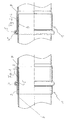
- the Figures 1 and 2 each show a longitudinal section through a pipe joint 1 with a press fitting 2 according to the invention.
- the press fitting 2 consists of a sleeve-like region 3, which is either cylindrical or toroidal, depending on whether it is a curved piece or a rectilinearly extending fitting.
- the end of the sleeve-like region of the press fitting 2 has a circumferential bead 4, which in turn receives an annular sealing element 5 made of rubber-elastic material.
- the press fitting 2 receives a smooth-walled pipe end 6, which is inserted in this up to a stop 7.
- the stopper 7 can be formed either by a cross-sectional tapering of the sleeve-like region 3 or by individual impressions which protrude into the inner cross-section thereof. In the case of in the Figures 1 and 2 1, the stopper 7 is formed in each case by a cross-sectional taper of the sleeve-like region 3.
- the Press fittings 2 as shown in FIG. 1 and FIG. 2 differ in that in the case of in FIG. 1 illustrated embodiment, the bead 4 does not form the end face of the press fitting 2, but that on both sides of the bead 4 each extending a portion of the sleeve-like portion 3 extends. At the in FIG. 2 illustrated embodiment, however, the bead 4 forms the frontal end of the press fitting. 2
- the Figures 1 and 2 show the pipe joint 2 in the unpressed state.
- the bead-shaped region of the press fitting 2, ie the bead 4 and the immediately adjoining region of the fitting body are pressed in the region of the plastic deformation by means of a pressing tool having a pressing jaw.
- the sealing element 5 is radially compressed, so that this line abuts the outer wall of the tube 6.
- the sealing element 5 can also bear against the outer wall of the tube 6 even in the unpressed state of the press fitting 2.
- the leakage is used to detect any unpressed pipe connections. It may happen that a leak occurs only when pressure shock load of the line. This surge load is relatively high, for example, when using one-hand lever armatures.
- sealing element 5 is such that in the unpressed state of the pipe joint 1, an axial passage between the sealing element 5 and the outer wall of the tube 6 is created.
- the formation of the sealing element 5 is in the FIGS. 3 to 10 illustrated.
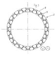
- FIG. 3 shows a first variant of the sealing element, in which the sealing surface 8 of the sealing element 5 is similar to a tire profile with labyrinth-like and communicating channels 9 interspersed.
- the channels 9 form axial passages between the outer wall of the inserted tube. 6 and the sealing element 5 in the unpressed state of the pipe joint1.
- the sealing element 5 is radially compressed so that the channels 9 are compressed and a contiguous sealing surface 8 is formed.
- FIGS. 4 and 5 show a second variant of the sealing element 5, in which the channels 9 pass through the sealing surface 8 only over part of the circumference of the sealing element 5.
- the channels 9 for example, on the voltage applied to the outer wall of the tube 6 in the installed position side of the sealing element, ie radially inwardly, omitted or interrupted.
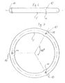
- the sealing element 5 is designed as a sealing cord with a round cross section, wherein at an angular distance of 120 ° over the circulation of the sealing element 5 toroidal thickenings 10 are provided, which are each axially interspersed with holes 11.
- Axial means in this context in the direction of the longitudinal extent of the press fitting 2.
- D. h. That in this direction axial passages are created, which are closed due to the accumulation of volume in the region of the thickenings 10 in the compressed state.
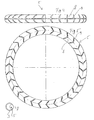
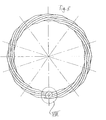
- FIGS. 8 . 9 and 10 Another variant of the sealing element 5 according to the invention is in the FIGS. 8 . 9 and 10 shown.
- the sealing element 5 has over its entire circulation a constant cross-section, in the case of FIG. 8 an octagonal cross-section, as can be seen from the cross-sectional view designated VIII.
- This in relation to the circumferential direction of the sealing element 5 extending central axis of the same non-rotationally symmetrical cross section is rotated over the circulation of the sealing element 5 in itself, so that in the unpressed state gaps between the bead 4 and the sealing element 5 and gaps between the sealing element. 5 and the outer surface of the tube 6 arise.
- the sealing element 5 is not twisted in tension in itself, but is in the relaxed and unpressed state, as in FIG. 5 represented, dimensionally stable.
- the sealing element 5 has a constant cross-section over its entire circumference, which assumes a different angular position in regions with respect to an axis of symmetry through the geometric center of gravity or with respect to the circumferential axis of the sealing element 5.
- the cross section is elliptical and the sealing element 5 is divided over its circulation in eight arc segments, wherein in each of the arc segments, the cross section of the sealing element 5 is arranged rotated by 90 °.
Landscapes
- Engineering & Computer Science (AREA)
- General Engineering & Computer Science (AREA)
- Mechanical Engineering (AREA)
- Gasket Seals (AREA)
- Non-Disconnectible Joints And Screw-Threaded Joints (AREA)
- Quick-Acting Or Multi-Walled Pipe Joints (AREA)
- Multi-Conductor Connections (AREA)
- Connections By Means Of Piercing Elements, Nuts, Or Screws (AREA)
- Press Drives And Press Lines (AREA)
- Automatic Assembly (AREA)
- Diaphragms For Electromechanical Transducers (AREA)
- Joints With Sleeves (AREA)
Description
- Die Erfindung betrifft einen Pressfitting zur Herstellung einer unlösbar dichten Verbindung von glattendigen Rohren, mit wenigstens einem muffenartig ausgebildetem Querschnitt und wenigstens einer etwa endseitig des Muffenabschnitts vorgesehenen Sicke, die wenigstens ein ringförmiges gummielastisches Dichtelement aufnimmt.
- Ein solcher Pressfitting ist beispielsweise aus der
DE 101 18 956 C1 bekannt. Auch aus derDE 197 22 935 C1 ist ein solcher Pressfitting bekannt. Die Abdichtung der jeweils endseitig in den Fitting eingeschobenen glattendigen Rohre wird dadurch erreicht, dass durch plastische Verformung des wulstartig ausgebildeten Endes des Pressfittings der Dichtring elastisch verformt wird, um über einen bestimmten Teil des Querschnittsumfangs linienförmig und/oder flächenförmig an den ihn umgebenden Oberflächenbereichen des wulstartig ausgebildeten Endes des Fittings und des Rohres zur Anlage zu kommen. Zur Aufnahme der bei entsprechendem Innendruck auftretenden Längskräfte wird der sich an die Sicke anschließende entweder zylindrisch oder torusförmig ausgebildete Abschnitt des Fittings zusammen mit dem Rohr plastisch verformt. - Nach Herstellung einer Rohrverbindung mittels Fittingen und Rohren wird diese üblicherweise einer Druckprobe unterzogen.
- Eine etwaige Leckage im Bereich der Verbindung muss bei einer solchen Druckprobe feststellbar sein. Um dies in jedem Falle zu gewährleisten, ist es bekannt, entweder den Fitting, d. h. die Sicke des Fittings oder den Dichtring, so auszubilden, dass diese im unverpressten Zustand undicht sind. Dies lässt sich entweder durch Dimensionierung des Dichtrings und/oder der Sicke oder durch entsprechende Oberflächengestaltung des Dichtrings bewerkstelligen.
- In der
DE 101 18 956 C1 wird beispielsweise vorgeschlagen, den Dichtring bzw. das Dichtelement mit einer Vielzahl kleiner hervorstehender Noppen zu versehen, so dass die Oberfläche des Dichtelements im unverpressten Zustand nur teilweise gegen die in den Pressfitting eingeschobene Rohrwandung anliegt. Es kommt so im unverpressten Zustand zu einer Durchlässigkeit des Dichtrings in axialer Richtung. - Eine vergleichbare Lösung wurde zuvor bereits in der
DE 197 22 935 C1 vorgeschlagen. Dort ist das Dichtelement mit mehreren in Umlaufrichtung liegenden Abschnitten versehen, die einen vom Ausgangsquerschnitt abweichenden Querschnitt in Form einer sich über den Umlauf und in die Querschnittsebene erstreckenden Ausbauchung und einer dem eingeschobenen Rohr zugewandten radial in den Querschnitt des Dichtelements sich erstreckenden Ausnehmung versehen ist, wobei das Volumen der Ausbauchung im Vergleich zum Ausgangsquerschnitt mindestens so groß ist wie das zum Ausgangsquerschnitt fehlende Volumen der Ausnehmung und vor der Verpressung im Querschnitt gesehen die Ausnehmung des Dichtelements eine Durchgangsöffnung in axialer Richtung bildet. - Das Dichtelement nach dieser Lösung ist verhältnismäßig aufwendig in der Herstellung und erfordert die genaueste Einhaltung von Fertigungstoleranzen.
- Bei der Lösung gemäss
DE 101 18 956 besteht die Gefahr, dass die feinen Noppen auf der Außenfläche des Dichtelements beim Einschub der Rohrenden abreißen oder verletzt werden. - Aus der
DE 298 13 935 ist eine unlösbare, durch Kaltverformung gebildete Pressverbindung zwischen einem Fitting und einem in eine Muffe des Fittings eingeführten Metallrohrende bekannt, wobei die Muffe eine zum Innenraum geöffnete, ringförmige Aufnahmenut für einen Dichtungsring aufweist. Dieses gummielastische Dichtungselement weist wenigstens eine Verdickung auf, die mit einer Durchbrechung durchsetzt ist. Die Durchbrechung wird erst nach Kaltverformung der Muffe und des Metallrohrendes durch ein Presswerkzeug gas- oder flüssigkeitsdicht verschlossen. - Der Durchbrechung ist am Außenumfang des Dichtungsrings eine Materialanhäufung zugeordnet, so dass bei Einschub eines glattwandigen Rohrendes in die Muffe die Gefahr besteht, dass sich die Durchbrechung so verdreht, dass diese insbesondere bei Fertigungsungenauigkeiten des Dichtrings verschlossen wird.
- Der Erfindung liegt daher die Aufgabe zu Grunde, einen Pressfitting der eingangs genannten Art so zu verbessern, dass die Auflagefläche zu dem Rohrende und der Sicke so gestaltet ist, dass die Lage und Funktion der Leckagestellen durch das Einschieben des glattwandigen Rohrendes nicht beeinträchtigt werden.
- Hierzu werden erfindungsgemäß mehrere Lösungen vorgeschlagen.
- Die der Erfindung zugrunde liegende Aufgabe wird zunächst dadurch gelöst, dass die Oberfläche des Dichtelements wenigstens bereichsweise mit rinnenförmig ausgebildeten Kanälen durchzogen ist, die im unverpressten Zustand des Dichtelements labyrinthartig miteinander kommunizieren, wobei die durch die Kanäle unterbrochenen Dichtflächen im verpressten Zustand die Kanäle verschließend aneinandergepresst sind.
- Als besonders vorteilhaft hat sich diese Lösung erwiesen, wenn die Dichtflächen des Dichtelements den größten Teil der Oberfläche des Dichtelements bilden.
- Nach einer weiteren Lösung der eingangs genannten Aufgabe ist ein Pressfitting mit Oberbegriff von Anspruch 1 vorgesehen, der sich dadurch auszeichnet, dass das Dichtelement über seinen gesamten Umlauf einen gleichen, nicht rotationssymmetrischen Querschnitt aufweist, der über den Umlauf des Dichtelements jeweils in Bezug auf eine Symmetrieachse durch den geometrischen Schwerpunkt eine andere Winkellage einnimmt. Der Querschnitt des Dichtelements ist also über den gesamten Umlauf desselben in sich verdreht, so dass im unverpressten Zustand Lücken zwischen Fittingwulst und Dichtelement sowohl als auch zwischen eingeschobenem Rohr und Dichtelement entstehen. Wird der Fitting verpresst, findet ein Volumenausgleich statt. Der Dichtring dichtet dabei sowohl gegen den Fittingwulst bzw. gegen die Sicke als auch gegen das eingeschobene Rohr ab. Diese Lösung ist sowohl fertigungstechnisch als auch von der Wirkungsweise des Dichtelements besonders elegant.
- Es besteht verhältnismäßig viel Freiheit bei der Wahl des Querschnitts des Dichtelements, was ebenfalls fertigungstechnisch von Vorteil ist.
- Das Dichtelement kann beispielsweise einen vieleckigen Querschnitt aufweisen, der über den Umlauf des Dichtelements in sich verdreht ist. Alternativ hierzu kann das Dichtelement einen elliptischen Querschnitt aufweisen, der selbstverständlich ebenfalls in Umlaufrichtung desselben in sich verdreht ist.
- Der Begriff "verdreht" im Sinne der Erfindung ist nicht so zu verstehen, dass die Dichtschnur in sich tordiert ist, sondern vielmehr so, dass das Dichtelement im spannungsfreien und unverpressten Zustand die zuvor beschriebene Geometrie aufweist.
- Die Erfindung wird nachstehend anhand mehrerer in den Zeichnungen dargestellter Ausführungsbeispiele erläutert werden.
- Es zeigen :
- Fig.1
- einen schematischen Querschnitt durch eine Rohrverbindung gemäss der Erfindung,
- Fig. 2
- eine schematische Ansicht durch eine Rohrverbindung gemäss der Erfindung bei einer alternativen Ausgestaltung des Pressfittings,
- Fig. 3
- eine Ansicht einer ersten Ausführungsform des Dichtelements gemäss der Erfindung in Perspektive,
- Fig. 4
- eine perspektivische Draufsicht auf ein Dichtelement nach einer zweiten Ausführungsform der Erfindung,
- Fig. 5
- eine Seitenansicht des in
Figur 4 dargestellten Dichtelements in Perspektive, - Fig. 6
- eine perspektivische Draufsicht auf ein Dichtelement nach eine dritten Ausführungsform, die nicht Teil der Erfindung ist,
- Fig. 7
- eine Seitenansicht des in
Figur 6 dargestellten Dichtelements, - Fig. 8
- eine schematische Darstellung des Dichtelements gemäss der Erfindung nach einer vierten Ausführungsform, teilweise im Schnitt,
- Fig. 9
- eine schematische Draufsicht auf das Dichtelement gemäß einer fünften Ausführungsform der Erfindung, teilweise im Schnitt und
- Fig. 10
- eine Seitenansicht des in
Figur 9 dargestellten Dichtelements, teilweise im Schnitt. - Die
Figuren 1 und 2 zeigen jeweils einen Längsschnitt durch eine Rohrverbindung 1 mit einem Pressfitting 2 gemäss der Erfindung. Der Pressfitting 2 besteht aus einem muffenartig ausgebildeten Bereich 3, der entweder zylindrisch oder torusförmig ist, je nach dem, ob es sich um ein Bogenstück oder ein in sich gradlinig erstreckenden Fitting handelt. Jeweils endseitig des muffenartig ausgebildeten Bereichs weist der Pressfitting 2 eine umlaufende Sicke 4 auf, die wiederum ein ringförmiges Dichtelement 5 aus gummielastischem Material aufnimmt. Der Pressfitting 2 nimmt ein glattwandiges Rohrende 6 auf, welches in diesem bis zu einem Anschlag 7 eingeschoben wird. Der Anschlag 7 kann entweder durch eine Querschnittsverjüngung des muffenartig ausgebildeten Bereichs 3 oder durch einzelne Einprägungen, die in den Innenquerschnitt desselben hervortreten, gebildet werden. Im Falle der in denFiguren 1 und 2 dargestellten Rohrverbindungen 1 wird der Anschlag 7 jeweils durch eine Querschnittsverjüngung des muffenartig ausgebildeten Bereichs 3 gebildet. Die Pressfittinge 2 gemäss Darstellung inFigur 1 und Figur 2 unterscheiden sich dadurch, dass im Falle des inFigur 1 dargestellten Ausführungsbeispiels die Sicke 4 nicht den stirnseitigen Abschluss des Pressfittings 2 bildet, sondern dass sich beidseitig der Sicke 4 jeweils ein Abschnitt des muffenartig ausgebildeten Bereichs 3 erstreckt. Bei dem inFigur 2 dargestellten Ausführungsbeispiel hingegen bildet die Sicke 4 den stirnseitigen Abschluss des Pressfittings 2. - Die
Figuren 1 und 2 zeigen die Rohrverbindung 2 im unverpressten Zustand. Üblicherweise werden der wulstartig ausgebildete Bereich des Pressfittings 2, d. h. die Sicke 4 und der unmittelbar sich daran anschließende Bereich des Fittingkörpers mittels eines Pressbacken aufweisenden Presswerkzeuges im Bereich der plastischen Verformung verpresst. Dabei wird das Dichtelement 5 radial komprimiert, so dass dieses linienförmig an der Außenwandung des Rohrs 6 anliegt. Das Dichtelement 5 kann auch bereits im unverpressten Zustand des Pressfittings 2 gegen die Außenwandung des Rohres 6 anliegen. - Wie eingangs bereits beschrieben, kann es bei Druckprüfung der Rohrverbindung vorkommen, dass auch bei unverpresster Rohrverbindung keine Leckage auftritt, was nicht wünschenswert ist.
- Die Leckage wird dazu genutzt, gegebenenfalls un-verpresste Rohrverbindungen zu detektieren. Es kann nämlich vorkommen, dass eine Leckage erst bei Druckstoßbelastung der Leitung auftritt. Diese Druckstoßbelastung ist beispielsweise bei der Verwendung von Einhandmischhebelarmaturen verhältnismäßig hoch.
- Hierzu ist erfindungsgemäß Dichtelement 5 so beschaffen, dass im unverpressten Zustand der Rohrverbindung 1 ein axialer Durchgang zwischen dem Dichtelement 5 und der Außenwandung des Rohrs 6 geschaffen wird. Die Ausbildung des Dichtelements 5 ist in den
Figuren 3 bis 10 veranschaulicht.Figur 3 zeigt eine erste Variante des Dichtelements, bei welchem die Dichtfläche 8 des Dichtelements 5 ähnlich einem Reifenprofil mit labyrinthartig ausgebildeten und miteinander kommunizierenden Kanälen 9 durchsetzt ist. Die Kanäle 9 bilden axiale Durchgänge zwischen der Außenwandung des eingeschobenen Rohres 6 und dem Dichtelement 5 im unverpressten Zustand der Rohrverbindung1. - Sobald die Rohrverbindung 1 verpresst wird, wird das Dichtelement 5 radial so komprimiert, dass die Kanäle 9 zusammengedrückt werden und eine zusammenhängende Dichtfläche 8 entsteht.
- Die
Figuren 4 und 5 zeigen eine zweite Variante des Dichtelements 5, bei dem die Kanäle 9 die Dichtfläche 8 nur über einen Teil des Umfangs des Dichtelements 5 durchziehen. Hier sind die Kanäle 9 beispielsweise an der in Einbaulage an der Außenwandung des Rohrs 6 anliegenden Seite des Dichtelements, d. h. radial einwärts, ausgelassen bzw. unterbrochen. - Das in den
Figuren 6 und 7 dargestellte Dichtelement ist nicht Teil der Erfindung. Das Dichtelement 5 ist als Dichtschnur mit rundem Querschnitt ausgebildet, wobei im Winkelabstand von 120° über den Umlauf des Dichtelements 5 torusförmige Verdickungen 10 vorgesehen sind, die jeweils axial mit Bohrungen 11 durchsetzt sind. Axial heißt in diesem Zusammenhang in Richtung der Längserstreckung des Pressfittings 2. D. h., dass in dieser Richtung axiale Durchgänge geschaffen werden, die aufgrund der Volumenanhäufung im Bereich der Verdickungen 10 im verpressten Zustand verschlossen werden. - Eine weitere Variante des erfindungsgemäßen Dichtelements 5 ist in den
Figuren 8 ,9 und 10 dargestellt. Das Dichtelement 5 hat über seinen gesamten Umlauf einen gleichbleibenden Querschnitt, im Falle derFigur 8 einen achteckigen Querschnitt, wie aus der mit VIII bezeichneten Querschnittsansicht ersichtlich ist. Dieser in Bezug auch auf die sich in Umlaufrichtung des Dichtelements 5 erstreckende Mittelachse desselben nicht rotationssymmetrische Querschnitt ist über den Umlauf des Dichtelements 5 in sich verdreht, so dass im unverpressten Zustand Lücken zwischen der Sicke 4 und dem Dichtelement 5 als auch Lücken zwischen dem Dichtelement 5 und der Außenfläche des Rohres 6 entstehen. Wie vorstehend bereits erwähnt, ist das Dichtelement 5 nicht unter Spannung in sich tordiert, sondern ist im entspannten und unverpressten Zustand, wie inFigur 5 dargestellt, formstabil. - Eine Alternative des zuvor beschriebenen Lösungsprinzips ist in den
Figuren 9 und 10 dargestellt. Auch hier hat das Dichtelement 5 über seinen gesamten Umlauf einen gleichbleibenden Querschnitt, der bereichsweise in Bezug auf eine Symmetrieachse durch den geometrischen Schwerpunkt bzw. in Bezug auf die umlaufende Achse des Dichtelements 5 eine andere Winkellage einnimmt. Bei dem dargestellten Ausführungsbeispiel ist der Querschnitt elliptisch und das Dichtelement 5 ist über seinen Umlauf in acht Bogensegmente unterteilt, wobei in jedem der Bogensegmente der Querschnitt des Dichtelements 5 jeweils um 90° verdreht angeordnet ist. -
- 1
- Rohrverbindung
- 2
- Pressfitting
- 3
- muffenartig ausgebildeter Bereich
- 4
- Sicke
- 5
- Dichtelement
- 6
- Rohr
- 7
- Anschlag
- 8
- Dichtfläche
- 9
- Kanäle
- 10
- Verdickungen
- 11
- Bohrungen
- 12
- Bogensegment
Claims (5)
- Pressfitting (2) zur Herstellung einer unlösbar dichten Verbindung von glattendigen Rohren, mit wenigstens einem muffenartig ausgebildeten Abschnitt (3) und mit wenigstens einer etwa endseitig des Muffenabschnitts vorgesehenen Sicke (4), die wenigstens ein ringförmiges, gummielastisches Dichtelement (5) aufnimmt, dadurch gekennzeichnet, dass die Oberfläche des Dichtelements (5) wenigstens bereichsweise mit rinnenförmig ausgebildeten Kanälen (9) durchzogen ist, die im unverpressten Zustand des Dichtelements (5) labyrinthartig miteinander kommunizieren, wobei die durch die Kanäle (9) unterbrochenen Dichtflächen (8) im verpressten Zustand die Kanäle (9) verschließend aneinander gepresst sind.
- Pressfitting nach Anspruch 1, dadurch gekennzeichnet, dass die Dichtflächen (8) des Dichtelements (5) den größten Teil der Oberfläche des Dichtelements (5) bilden.
- Pressfitting (2) zur Herstellung einer unlösbar dichten Verbindung von glattendigen Rohren, mit wenigstens einem muffenartig ausgebildeten Abschnitt (3) und mit wenigstens einer etwa endseitig des Muffenabschnitts vorgesehenen Sicke (4), die wenigstens ein ringförmiges, gummielastisches Dichtelement (5) aufnimmt, dadurch gekennzeichnet, dass das Dichtelement (5) über seinen Umlauf einen gleichen, nicht rotationssymetrischen Querschnitt aufweist, der über den Umlauf des Dichtelements(5) jeweils in Bezug auf eine Symetrieachse durch den geometrischen Schwerpunkt des Querschnitts eine andere Winkellage einnimmt.
- Pressfitting nach Anspruch 3, dadurch gekennzeichnet, dass das Dichtelement (5) einen vieleckigen Querschnitt aufweist, der über den Umlauf des Dichtelements (5) in sich verdreht ist.
- Pressfitting nach Anspruch 3, dadurch gekennzeichnet, dass das Dichtelement (5) einen elliptischen Querschnitt aufweist.
Applications Claiming Priority (3)
| Application Number | Priority Date | Filing Date | Title |
|---|---|---|---|
| DE10303296 | 2003-01-28 | ||
| DE10303296A DE10303296B3 (de) | 2003-01-28 | 2003-01-28 | Pressfitting |
| PCT/DE2003/003971 WO2004068018A1 (de) | 2003-01-28 | 2003-12-03 | Pressfitting |
Publications (2)
| Publication Number | Publication Date |
|---|---|
| EP1588086A1 EP1588086A1 (de) | 2005-10-26 |
| EP1588086B1 true EP1588086B1 (de) | 2008-06-18 |
Family
ID=32603000
Family Applications (1)
| Application Number | Title | Priority Date | Filing Date |
|---|---|---|---|
| EP03788840A Expired - Lifetime EP1588086B1 (de) | 2003-01-28 | 2003-12-03 | Pressfitting |
Country Status (12)
| Country | Link |
|---|---|
| US (1) | US7475918B2 (de) |
| EP (1) | EP1588086B1 (de) |
| JP (1) | JP4167657B2 (de) |
| CN (1) | CN100387889C (de) |
| AT (1) | ATE398747T1 (de) |
| AU (1) | AU2003293000A1 (de) |
| DE (2) | DE10303296B3 (de) |
| NO (1) | NO337817B1 (de) |
| PL (1) | PL204712B1 (de) |
| RU (1) | RU2303741C2 (de) |
| UA (1) | UA80320C2 (de) |
| WO (1) | WO2004068018A1 (de) |
Families Citing this family (25)
| Publication number | Priority date | Publication date | Assignee | Title |
|---|---|---|---|---|
| DE202006004457U1 (de) * | 2006-03-21 | 2006-05-11 | Ipa Produktions- & Vertriebsges.M.B.H. | Struktur-O-Ring |
| EP1847753B1 (de) * | 2006-04-19 | 2008-11-05 | IBP Conex Limited | Dichtelement mit Leckage-Anzeige der unverpressten Rohrverbindung und Rohrverbindung mit einem solchen Dichtelement |
| DE102006023143A1 (de) * | 2006-05-16 | 2007-11-22 | Huf Hülsbeck & Fürst Gmbh & Co. Kg | Elektronischer Schlüssel |
| DE102006050427A1 (de) * | 2006-08-22 | 2008-02-28 | Gustav Klauke Gmbh | Verfahren zum Verpressen eines Pressfittings sowie Presswerkzeug hierzu |
| DE102006057721A1 (de) | 2006-12-01 | 2008-06-05 | Geberit Technik Ag | Rohrverbindung |
| US9188260B2 (en) | 2008-08-01 | 2015-11-17 | Nibco Inc. | Crimp evident seal |
| PT2196713E (pt) * | 2008-12-12 | 2012-08-30 | Conex Universal Ltd | Dispositivo, método e jogo de peças para formar uma união de montagem à pressão com um tubo |
| US20100253066A1 (en) * | 2009-04-02 | 2010-10-07 | Victaulic Company | Crimp-Type Coupling, Crimping Tool and Method of Crimping |
| US8585100B2 (en) * | 2009-08-27 | 2013-11-19 | Elkhart Products Corporation | Press-connect fitting with improved grab ring function |
| US9482374B2 (en) * | 2009-09-17 | 2016-11-01 | Victaulic Company | Seal having projections and coupling having pockets |
| ES2386569B1 (es) * | 2010-01-04 | 2013-05-16 | Jose Gonzalez Riera | Accesorio para tuberias |
| RU2432517C1 (ru) * | 2010-06-07 | 2011-10-27 | Общество с ограниченной ответственностью "Мордовская Трубная компания" | Способ соединения многослойных металлополимерных труб |
| ITMI20110676A1 (it) * | 2011-04-20 | 2012-10-21 | Eurotubi Europa S R L | O-ring gocciolante per raccordi a pressione fra tubi |
| US9638360B2 (en) * | 2012-02-14 | 2017-05-02 | Mueller Industries, Inc. | Leak detection O-ring |
| NL2015413B1 (en) * | 2015-09-08 | 2017-03-22 | Vsh Fittings B V | Press fitting for pipes having a check ring. |
| US9903515B2 (en) | 2015-12-09 | 2018-02-27 | Victaulic Company | Seal with lip projections |
| KR101954308B1 (ko) * | 2018-06-08 | 2019-03-05 | 정우금속공업 주식회사 | 파이프 연결용 실링부재 |
| US11371639B2 (en) * | 2018-08-09 | 2022-06-28 | Hanon Systems | Seal configuration to prevent damage from explosive decompression |
| US20200300391A1 (en) | 2019-03-20 | 2020-09-24 | Nibco Inc. | Press fitting assembly |
| US12060954B2 (en) | 2019-03-26 | 2024-08-13 | Nibco Inc. | Piping component and sealing element for insertion therein |
| KR200492249Y1 (ko) * | 2019-04-22 | 2020-09-04 | 조경호 | 관 이음구용 고무링 |
| US11320069B2 (en) | 2019-07-22 | 2022-05-03 | Parker-Hannifin Corporation | Threaded coupling with under-torque prevention |
| JP7165161B2 (ja) * | 2019-08-09 | 2022-11-02 | 株式会社三五 | 建築用配管システム及び当該システムの施工方法 |
| NL2024068B1 (en) * | 2019-10-21 | 2021-06-22 | Vsh Fittings B V | Profiled leak-before-press sealing ring for a press fitting with arc-shaped first type ring portions alternating with linear-shaped second type ring portions. |
| IT202200003905A1 (it) * | 2022-03-02 | 2023-09-02 | Vir Valvoindustria Ing Rizzio S P A | Sistema di giunzione tra raccordi e tubi |
Family Cites Families (23)
| Publication number | Priority date | Publication date | Assignee | Title |
|---|---|---|---|---|
| US856106A (en) * | 1906-04-02 | 1907-06-04 | Ada E Snow | Means for calking pipe-joints. |
| US2410786A (en) * | 1943-09-29 | 1946-11-05 | Wingfoot Corp | Joint for pressure suits |
| US2615740A (en) * | 1948-09-03 | 1952-10-28 | Hamilton Kent Mfg Company | Sealing ring |
| US2647770A (en) * | 1950-10-04 | 1953-08-04 | Atomic Energy Commission | Sealed telescopic pipe joint |
| US3315970A (en) * | 1965-02-08 | 1967-04-25 | John W Holoway | Flexible gasket for high and low pressure pipe joints |
| DE2963430D1 (en) * | 1978-10-27 | 1982-09-16 | Norske Remfabrik As | Gasket of rubber or similar material |
| US4371180A (en) * | 1980-03-24 | 1983-02-01 | The Marlo Company Incorporated | Gasket material |
| NO801521L (no) * | 1980-05-22 | 1981-11-23 | Rieber & Son As | Armert tetningsring. |
| JPH05602Y2 (de) * | 1988-06-30 | 1993-01-08 | ||
| US5161806A (en) * | 1990-12-17 | 1992-11-10 | Peter J. Balsells | Spring-loaded, hollow, elliptical ring seal |
| US5362115A (en) * | 1992-06-05 | 1994-11-08 | Carr Ronald L | Multi-ring gasket |
| US5551706A (en) * | 1993-04-20 | 1996-09-03 | W. L. Gore & Associates, Inc. | Composite gasket for sealing flanges and method for making and using same |
| FR2718193B1 (fr) * | 1994-04-01 | 1996-04-26 | Chatelain Michel | Segment d'étanchéité et son piston. |
| DE19544161C2 (de) * | 1994-12-27 | 1998-08-20 | Mannesmann Ag | Preßfitting zur Herstellung einer unlösbaren dichten Verbindung von Rohren |
| JP2991651B2 (ja) * | 1995-12-25 | 1999-12-20 | シーケーディ株式会社 | 金属ガスケット |
| DE19631574C1 (de) * | 1996-07-26 | 1997-11-13 | Mannesmann Ag | Rohrverbindung |
| DE19722935C1 (de) * | 1997-05-27 | 1998-07-09 | Mannesmann Ag | Preßfitting zur Herstellung einer unlösbaren Verbindung von Rohren |
| DE29813935U1 (de) * | 1998-08-04 | 1998-10-01 | Franz Viegener II GmbH & Co. KG, 57439 Attendorn | Unlösbare Preßverbindung zwischen einem Fitting und einem Metallrohrende |
| CN2376558Y (zh) * | 1999-03-30 | 2000-05-03 | 孙茂腾 | 一种o形密封圈 |
| DE10007914C1 (de) * | 2000-02-21 | 2001-09-06 | Franz Viegener Ii Gmbh & Co Kg | Fitting oder Armatur zur Herstellung einer Pressverbindung mit einem eingesteckten Rohrende |
| US6511076B1 (en) * | 2000-09-21 | 2003-01-28 | Siemens Westinghouse Power Corporation | Fiber gasket and method of making same |
| DE10118956C1 (de) * | 2001-04-10 | 2002-06-20 | Mapress Gmbh & Co Kg | Rohrverbindung |
| US6726256B2 (en) * | 2001-10-17 | 2004-04-27 | Franz Viegener Ii Gmbh & Co. Kg | Fitting or mounting part for establishing a pressed connection with an inserted tube end |
-
2003
- 2003-01-28 DE DE10303296A patent/DE10303296B3/de not_active Expired - Fee Related
- 2003-03-12 UA UAA200508350A patent/UA80320C2/uk unknown
- 2003-12-03 RU RU2005127072/06A patent/RU2303741C2/ru not_active IP Right Cessation
- 2003-12-03 WO PCT/DE2003/003971 patent/WO2004068018A1/de not_active Ceased
- 2003-12-03 CN CNB2003801100859A patent/CN100387889C/zh not_active Expired - Fee Related
- 2003-12-03 AT AT03788840T patent/ATE398747T1/de not_active IP Right Cessation
- 2003-12-03 EP EP03788840A patent/EP1588086B1/de not_active Expired - Lifetime
- 2003-12-03 US US10/543,784 patent/US7475918B2/en not_active Expired - Fee Related
- 2003-12-03 JP JP2004567246A patent/JP4167657B2/ja not_active Expired - Fee Related
- 2003-12-03 AU AU2003293000A patent/AU2003293000A1/en not_active Abandoned
- 2003-12-03 PL PL378220A patent/PL204712B1/pl unknown
- 2003-12-03 DE DE50310021T patent/DE50310021D1/de not_active Expired - Lifetime
-
2005
- 2005-08-26 NO NO20053985A patent/NO337817B1/no not_active IP Right Cessation
Also Published As
| Publication number | Publication date |
|---|---|
| PL204712B1 (pl) | 2010-02-26 |
| UA80320C2 (en) | 2007-09-10 |
| WO2004068018A1 (de) | 2004-08-12 |
| NO20053985D0 (no) | 2005-08-26 |
| CN100387889C (zh) | 2008-05-14 |
| DE50310021D1 (en) | 2008-07-31 |
| NO20053985L (no) | 2005-08-26 |
| JP2006513383A (ja) | 2006-04-20 |
| JP4167657B2 (ja) | 2008-10-15 |
| ATE398747T1 (de) | 2008-07-15 |
| AU2003293000A1 (en) | 2004-08-23 |
| PL378220A1 (pl) | 2006-03-20 |
| CN1756918A (zh) | 2006-04-05 |
| RU2303741C2 (ru) | 2007-07-27 |
| US20060175829A1 (en) | 2006-08-10 |
| EP1588086A1 (de) | 2005-10-26 |
| NO337817B1 (no) | 2016-06-27 |
| US7475918B2 (en) | 2009-01-13 |
| DE10303296B3 (de) | 2004-07-29 |
| RU2005127072A (ru) | 2006-01-20 |
Similar Documents
| Publication | Publication Date | Title |
|---|---|---|
| EP1588086B1 (de) | Pressfitting | |
| DE102007026394A1 (de) | Drehfester Schlauchanschluss | |
| DE3317061A1 (de) | Flanschverbindungsanordnung | |
| EP1564469A1 (de) | Fitting für eine Pressverbindung | |
| EP0733822A1 (de) | Mit Fluid gefüllte Zylinder-Kolbenstangen-Einheit, insbesondere Gasfeder | |
| EP1857724B1 (de) | Rohrverbindung mit einem umgeformten Rohr | |
| EP1759141B2 (de) | Fitting | |
| DE10118956C1 (de) | Rohrverbindung | |
| EP2278235A2 (de) | Anschlussteil einer Heizplatte eines Heizkörpers sowie Plattenheizkörper | |
| DE102018122507A1 (de) | Anschlussvorrichtung für Rohrleitungen mit Leckageanzeige | |
| DE102016003917A1 (de) | Buchsenanordnung zur Zentrierung zweier zu verbindender Wellenabschnitte | |
| DE10217824C1 (de) | Rohrverbindung | |
| WO2003045717A2 (de) | Gelenk | |
| DE10002916C1 (de) | Pressfittingelement | |
| EP0392148B1 (de) | Rohrverbindung | |
| EP1361386B1 (de) | Rohrpressverbindung | |
| DE102020134593A1 (de) | Hydraulische Buchse mit Abstützstellen und Verfahren zur Herstellung einer solchen Buchse | |
| EP1462702A2 (de) | Rohrverbindung mit einem umgeformten Rohr | |
| EP0503125B1 (de) | Pressverbindung | |
| DE2518619A1 (de) | Daempfer fuer druckstoesse bzw. schlaege in fluessigkeitsleitungen | |
| DE4042728B4 (de) | Anschlußvorrichtung für Hydraulik-Rohrleitungen | |
| WO2000028250A1 (de) | Rohrpressverbindung | |
| EP0879984B1 (de) | Anschlussarmatur für Schläuche | |
| DE69912149T2 (de) | Verbindungsvorrichtung einer metallischen rohrleitung | |
| WO2018206042A1 (de) | Anordnung zum verbinden eines ersten und eines zweiten leitungselements |
Legal Events
| Date | Code | Title | Description |
|---|---|---|---|
| PUAI | Public reference made under article 153(3) epc to a published international application that has entered the european phase |
Free format text: ORIGINAL CODE: 0009012 |
|
| 17P | Request for examination filed |
Effective date: 20050730 |
|
| AK | Designated contracting states |
Kind code of ref document: A1 Designated state(s): AT BE BG CH CY CZ DE DK EE ES FI FR GB GR HU IE IT LI LU MC NL PT RO SE SI SK TR |
|
| AX | Request for extension of the european patent |
Extension state: AL LT LV MK |
|
| RIN1 | Information on inventor provided before grant (corrected) |
Inventor name: KAIMER, BERND Inventor name: HERBERG, TOM |
|
| DAX | Request for extension of the european patent (deleted) | ||
| 17Q | First examination report despatched |
Effective date: 20070213 |
|
| GRAP | Despatch of communication of intention to grant a patent |
Free format text: ORIGINAL CODE: EPIDOSNIGR1 |
|
| GRAS | Grant fee paid |
Free format text: ORIGINAL CODE: EPIDOSNIGR3 |
|
| GRAA | (expected) grant |
Free format text: ORIGINAL CODE: 0009210 |
|
| AK | Designated contracting states |
Kind code of ref document: B1 Designated state(s): AT BE BG CH CY CZ DE DK EE ES FI FR GB GR HU IE IT LI LU MC NL PT RO SE SI SK TR |
|
| REG | Reference to a national code |
Ref country code: GB Ref legal event code: FG4D Free format text: NOT ENGLISH |
|
| REF | Corresponds to: |
Ref document number: 50310021 Country of ref document: DE Date of ref document: 20080731 Kind code of ref document: P |
|
| REG | Reference to a national code |
Ref country code: CH Ref legal event code: NV Representative=s name: FIAMMENGHI-FIAMMENGHI Ref country code: CH Ref legal event code: EP |
|
| REG | Reference to a national code |
Ref country code: IE Ref legal event code: FG4D Free format text: LANGUAGE OF EP DOCUMENT: GERMAN |
|
| PG25 | Lapsed in a contracting state [announced via postgrant information from national office to epo] |
Ref country code: SI Free format text: LAPSE BECAUSE OF FAILURE TO SUBMIT A TRANSLATION OF THE DESCRIPTION OR TO PAY THE FEE WITHIN THE PRESCRIBED TIME-LIMIT Effective date: 20080618 Ref country code: FI Free format text: LAPSE BECAUSE OF FAILURE TO SUBMIT A TRANSLATION OF THE DESCRIPTION OR TO PAY THE FEE WITHIN THE PRESCRIBED TIME-LIMIT Effective date: 20080618 |
|
| PG25 | Lapsed in a contracting state [announced via postgrant information from national office to epo] |
Ref country code: NL Free format text: LAPSE BECAUSE OF FAILURE TO SUBMIT A TRANSLATION OF THE DESCRIPTION OR TO PAY THE FEE WITHIN THE PRESCRIBED TIME-LIMIT Effective date: 20080618 |
|
| NLV1 | Nl: lapsed or annulled due to failure to fulfill the requirements of art. 29p and 29m of the patents act | ||
| PG25 | Lapsed in a contracting state [announced via postgrant information from national office to epo] |
Ref country code: SE Free format text: LAPSE BECAUSE OF FAILURE TO SUBMIT A TRANSLATION OF THE DESCRIPTION OR TO PAY THE FEE WITHIN THE PRESCRIBED TIME-LIMIT Effective date: 20080918 Ref country code: CZ Free format text: LAPSE BECAUSE OF FAILURE TO SUBMIT A TRANSLATION OF THE DESCRIPTION OR TO PAY THE FEE WITHIN THE PRESCRIBED TIME-LIMIT Effective date: 20080618 Ref country code: PT Free format text: LAPSE BECAUSE OF FAILURE TO SUBMIT A TRANSLATION OF THE DESCRIPTION OR TO PAY THE FEE WITHIN THE PRESCRIBED TIME-LIMIT Effective date: 20081118 Ref country code: ES Free format text: LAPSE BECAUSE OF FAILURE TO SUBMIT A TRANSLATION OF THE DESCRIPTION OR TO PAY THE FEE WITHIN THE PRESCRIBED TIME-LIMIT Effective date: 20080929 |
|
| REG | Reference to a national code |
Ref country code: IE Ref legal event code: FD4D |
|
| PG25 | Lapsed in a contracting state [announced via postgrant information from national office to epo] |
Ref country code: RO Free format text: LAPSE BECAUSE OF FAILURE TO SUBMIT A TRANSLATION OF THE DESCRIPTION OR TO PAY THE FEE WITHIN THE PRESCRIBED TIME-LIMIT Effective date: 20080618 Ref country code: SK Free format text: LAPSE BECAUSE OF FAILURE TO SUBMIT A TRANSLATION OF THE DESCRIPTION OR TO PAY THE FEE WITHIN THE PRESCRIBED TIME-LIMIT Effective date: 20080618 |
|
| PLBE | No opposition filed within time limit |
Free format text: ORIGINAL CODE: 0009261 |
|
| STAA | Information on the status of an ep patent application or granted ep patent |
Free format text: STATUS: NO OPPOSITION FILED WITHIN TIME LIMIT |
|
| PG25 | Lapsed in a contracting state [announced via postgrant information from national office to epo] |
Ref country code: IE Free format text: LAPSE BECAUSE OF FAILURE TO SUBMIT A TRANSLATION OF THE DESCRIPTION OR TO PAY THE FEE WITHIN THE PRESCRIBED TIME-LIMIT Effective date: 20080618 Ref country code: EE Free format text: LAPSE BECAUSE OF FAILURE TO SUBMIT A TRANSLATION OF THE DESCRIPTION OR TO PAY THE FEE WITHIN THE PRESCRIBED TIME-LIMIT Effective date: 20080618 Ref country code: DK Free format text: LAPSE BECAUSE OF FAILURE TO SUBMIT A TRANSLATION OF THE DESCRIPTION OR TO PAY THE FEE WITHIN THE PRESCRIBED TIME-LIMIT Effective date: 20080618 Ref country code: BG Free format text: LAPSE BECAUSE OF FAILURE TO SUBMIT A TRANSLATION OF THE DESCRIPTION OR TO PAY THE FEE WITHIN THE PRESCRIBED TIME-LIMIT Effective date: 20080918 |
|
| 26N | No opposition filed |
Effective date: 20090319 |
|
| BERE | Be: lapsed |
Owner name: KAIMER G.M.B.H. & CO. HOLDING KG Effective date: 20081231 |
|
| PG25 | Lapsed in a contracting state [announced via postgrant information from national office to epo] |
Ref country code: MC Free format text: LAPSE BECAUSE OF NON-PAYMENT OF DUE FEES Effective date: 20081231 |
|
| PG25 | Lapsed in a contracting state [announced via postgrant information from national office to epo] |
Ref country code: BE Free format text: LAPSE BECAUSE OF NON-PAYMENT OF DUE FEES Effective date: 20081231 |
|
| PG25 | Lapsed in a contracting state [announced via postgrant information from national office to epo] |
Ref country code: AT Free format text: LAPSE BECAUSE OF NON-PAYMENT OF DUE FEES Effective date: 20081203 |
|
| PG25 | Lapsed in a contracting state [announced via postgrant information from national office to epo] |
Ref country code: CY Free format text: LAPSE BECAUSE OF FAILURE TO SUBMIT A TRANSLATION OF THE DESCRIPTION OR TO PAY THE FEE WITHIN THE PRESCRIBED TIME-LIMIT Effective date: 20080618 Ref country code: HU Free format text: LAPSE BECAUSE OF FAILURE TO SUBMIT A TRANSLATION OF THE DESCRIPTION OR TO PAY THE FEE WITHIN THE PRESCRIBED TIME-LIMIT Effective date: 20081219 |
|
| PG25 | Lapsed in a contracting state [announced via postgrant information from national office to epo] |
Ref country code: TR Free format text: LAPSE BECAUSE OF FAILURE TO SUBMIT A TRANSLATION OF THE DESCRIPTION OR TO PAY THE FEE WITHIN THE PRESCRIBED TIME-LIMIT Effective date: 20080618 |
|
| PG25 | Lapsed in a contracting state [announced via postgrant information from national office to epo] |
Ref country code: GR Free format text: LAPSE BECAUSE OF FAILURE TO SUBMIT A TRANSLATION OF THE DESCRIPTION OR TO PAY THE FEE WITHIN THE PRESCRIBED TIME-LIMIT Effective date: 20080919 |
|
| REG | Reference to a national code |
Ref country code: CH Ref legal event code: PFUS Owner name: SANHA GMBH CO. KG, DE Free format text: FORMER OWNER: KAIMER GMBH CO. HOLDING KG, DE |
|
| REG | Reference to a national code |
Ref country code: FR Ref legal event code: TP Owner name: SANHA GMBH & CO.KG, DE Effective date: 20120717 Ref country code: FR Ref legal event code: CD Owner name: SANHA GMBH & CO.KG, DE Effective date: 20120717 |
|
| REG | Reference to a national code |
Ref country code: GB Ref legal event code: 732E Free format text: REGISTERED BETWEEN 20120726 AND 20120801 |
|
| REG | Reference to a national code |
Ref country code: DE Ref legal event code: R082 Ref document number: 50310021 Country of ref document: DE Representative=s name: FLEISCHER, GODEMEYER, KIERDORF & PARTNER, PATE, DE Effective date: 20120830 Ref country code: DE Ref legal event code: R081 Ref document number: 50310021 Country of ref document: DE Owner name: SANHA GMBH & CO. KG, DE Free format text: FORMER OWNER: KAIMER GMBH & CO. HOLDING KG, 45219 ESSEN, DE Effective date: 20120830 Ref country code: DE Ref legal event code: R082 Ref document number: 50310021 Country of ref document: DE Representative=s name: KIERDORF RITSCHEL PATENTANWAELTE PARTG MBB, DE Effective date: 20120830 Ref country code: DE Ref legal event code: R082 Ref document number: 50310021 Country of ref document: DE Representative=s name: KIERDORF RITSCHEL RICHLY PATENTANWAELTE PARTG , DE Effective date: 20120830 |
|
| REG | Reference to a national code |
Ref country code: DE Ref legal event code: R082 Ref document number: 50310021 Country of ref document: DE Representative=s name: KIERDORF RITSCHEL PATENTANWAELTE PARTG MBB, DE Ref country code: DE Ref legal event code: R082 Ref document number: 50310021 Country of ref document: DE Representative=s name: KIERDORF RITSCHEL RICHLY PATENTANWAELTE PARTG , DE |
|
| REG | Reference to a national code |
Ref country code: FR Ref legal event code: PLFP Year of fee payment: 13 |
|
| REG | Reference to a national code |
Ref country code: FR Ref legal event code: PLFP Year of fee payment: 14 |
|
| REG | Reference to a national code |
Ref country code: FR Ref legal event code: PLFP Year of fee payment: 15 |
|
| PGFP | Annual fee paid to national office [announced via postgrant information from national office to epo] |
Ref country code: FR Payment date: 20171221 Year of fee payment: 15 Ref country code: LU Payment date: 20171219 Year of fee payment: 15 Ref country code: DE Payment date: 20171128 Year of fee payment: 15 |
|
| PGFP | Annual fee paid to national office [announced via postgrant information from national office to epo] |
Ref country code: GB Payment date: 20171221 Year of fee payment: 15 Ref country code: CH Payment date: 20171220 Year of fee payment: 15 |
|
| PGFP | Annual fee paid to national office [announced via postgrant information from national office to epo] |
Ref country code: IT Payment date: 20171221 Year of fee payment: 15 |
|
| REG | Reference to a national code |
Ref country code: DE Ref legal event code: R119 Ref document number: 50310021 Country of ref document: DE |
|
| REG | Reference to a national code |
Ref country code: CH Ref legal event code: PL |
|
| GBPC | Gb: european patent ceased through non-payment of renewal fee |
Effective date: 20181203 |
|
| PG25 | Lapsed in a contracting state [announced via postgrant information from national office to epo] |
Ref country code: LU Free format text: LAPSE BECAUSE OF NON-PAYMENT OF DUE FEES Effective date: 20181203 |
|
| PG25 | Lapsed in a contracting state [announced via postgrant information from national office to epo] |
Ref country code: FR Free format text: LAPSE BECAUSE OF NON-PAYMENT OF DUE FEES Effective date: 20181231 Ref country code: IT Free format text: LAPSE BECAUSE OF NON-PAYMENT OF DUE FEES Effective date: 20181203 Ref country code: DE Free format text: LAPSE BECAUSE OF NON-PAYMENT OF DUE FEES Effective date: 20190702 |
|
| PG25 | Lapsed in a contracting state [announced via postgrant information from national office to epo] |
Ref country code: GB Free format text: LAPSE BECAUSE OF NON-PAYMENT OF DUE FEES Effective date: 20181203 Ref country code: CH Free format text: LAPSE BECAUSE OF NON-PAYMENT OF DUE FEES Effective date: 20181231 Ref country code: LI Free format text: LAPSE BECAUSE OF NON-PAYMENT OF DUE FEES Effective date: 20181231 |