EP1588330B1 - Identification de vehicule - Google Patents
Identification de vehicule Download PDFInfo
- Publication number
- EP1588330B1 EP1588330B1 EP04706403A EP04706403A EP1588330B1 EP 1588330 B1 EP1588330 B1 EP 1588330B1 EP 04706403 A EP04706403 A EP 04706403A EP 04706403 A EP04706403 A EP 04706403A EP 1588330 B1 EP1588330 B1 EP 1588330B1
- Authority
- EP
- European Patent Office
- Prior art keywords
- vehicle
- exit
- control
- barrier
- car
- Prior art date
- Legal status (The legal status is an assumption and is not a legal conclusion. Google has not performed a legal analysis and makes no representation as to the accuracy of the status listed.)
- Expired - Lifetime
Links
Images


Classifications
-
- G—PHYSICS
- G07—CHECKING-DEVICES
- G07B—TICKET-ISSUING APPARATUS; FARE-REGISTERING APPARATUS; FRANKING APPARATUS
- G07B15/00—Arrangements or apparatus for collecting fares, tolls or entrance fees at one or more control points
- G07B15/02—Arrangements or apparatus for collecting fares, tolls or entrance fees at one or more control points taking into account a variable factor such as distance or time, e.g. for passenger transport, parking systems or car rental systems
- G07B15/04—Arrangements or apparatus for collecting fares, tolls or entrance fees at one or more control points taking into account a variable factor such as distance or time, e.g. for passenger transport, parking systems or car rental systems comprising devices to free a barrier, turnstile, or the like
-
- E—FIXED CONSTRUCTIONS
- E04—BUILDING
- E04H—BUILDINGS OR LIKE STRUCTURES FOR PARTICULAR PURPOSES; SWIMMING OR SPLASH BATHS OR POOLS; MASTS; FENCING; TENTS OR CANOPIES, IN GENERAL
- E04H6/00—Buildings for parking cars, rolling-stock, aircraft, vessels or like vehicles, e.g. garages
- E04H6/08—Garages for many vehicles
-
- G—PHYSICS
- G01—MEASURING; TESTING
- G01B—MEASURING LENGTH, THICKNESS OR SIMILAR LINEAR DIMENSIONS; MEASURING ANGLES; MEASURING AREAS; MEASURING IRREGULARITIES OF SURFACES OR CONTOURS
- G01B11/00—Measuring arrangements characterised by the use of optical techniques
- G01B11/24—Measuring arrangements characterised by the use of optical techniques for measuring contours or curvatures
-
- G—PHYSICS
- G06—COMPUTING OR CALCULATING; COUNTING
- G06K—GRAPHICAL DATA READING; PRESENTATION OF DATA; RECORD CARRIERS; HANDLING RECORD CARRIERS
- G06K7/00—Methods or arrangements for sensing record carriers, e.g. for reading patterns
- G06K7/10—Methods or arrangements for sensing record carriers, e.g. for reading patterns by electromagnetic radiation, e.g. optical sensing; by corpuscular radiation
- G06K7/14—Methods or arrangements for sensing record carriers, e.g. for reading patterns by electromagnetic radiation, e.g. optical sensing; by corpuscular radiation using light without selection of wavelength, e.g. sensing reflected white light
-
- G—PHYSICS
- G08—SIGNALLING
- G08G—TRAFFIC CONTROL SYSTEMS
- G08G1/00—Traffic control systems for road vehicles
- G08G1/01—Detecting movement of traffic to be counted or controlled
- G08G1/017—Detecting movement of traffic to be counted or controlled identifying vehicles
Definitions
- the present invention relates to the identification of vehicles.
- the present invention relates to the identification of vehicles when entering and exiting a monitored area, for example a car park or at national boundaries.
- the invention relates to a method that prevents the theft of vehicles from a car park, and an arrangement for carrying out the method.
- Road tolls are increasingly common and, for such road tolls, it is important to be able to identify vehicles without the traffic flow being interrupted too much, in order to be able to charge for the vehicle. Also for automatic traffic monitoring, at barriers to protected areas or more generally for monitored areas, it is important to be able to identify a vehicle.
- the registration number is read automatically by image processing.
- image processing requires a high-quality image in order that an incorrect registration number should not be read off, which complicates such a method. For example, dirt and snow can prevent the correct reading of the registration number.
- Entering and exiting car parks can, for example, be carried out in such a way that the driver obtains a car park ticket at an entrance barrier upon which the time is recorded. Before the vehicle is retrieved, payment for the parking must be made, which is checked by means of the car park ticket at an exit barrier, after which the car is allowed to leave.
- a disadvantage of this system is that no check is made that it is the same car at the exit as at the entrance. The driver may, for example, have parked an old car in poor condition and obtained a car park ticket, in order later to steal a valuable car and drive it out of the car park using his car park ticket.
- Another problem is the theft of vehicles by tailgating, that is a stolen vehicle is driven out closely behind another vehicle that is allowed out through the exit barrier.
- US 4775571 describes a similar solution, but where in addition a picture of the registration plate is transferred onto a car park ticket both at the entrance and at the exit, with both these tickets having to be handed in at the exit barrier together with the payment in order for the car to be allowed to leave.
- a disadvantage of these two previously known systems is that the theft of a vehicle can still be carried out by transferring the registration plate to another more valuable car.
- GB 2 273 596 describes a vehicle protection system in which data that identifies both the vehicle and the driver are stored together when entering the car park. When exiting, the identities of both the driver and the vehicle are then checked and compared with the stored information. The vehicle identification is carried out by means of a video camera, among other things for obtaining the registration number. It is mentioned, however, that other characteristics of the vehicle can also be determined, such as the orientation of the screws that hold the registration plate and nuances in the vehicle's color.
- BE 1010751 also describes a theft prevention system for a car park, where an image is recorded of the vehicle when entering and the image is analyzed, after which the result of the analysis is transferred onto a car park ticket. When exiting, another image of the vehicle is recorded which is analyzed, after which the result of the analysis is compared with the data on the car park ticket. If the data is the same, the vehicle is allowed to leave.
- the main aim of the present invention is thus to provide an apparatus and a method for making it possible to identify a vehicle.
- An additional particular aim of the present invention is to identify the type of vehicle by recognizing the position and orientation of reflectors on the vehicle.
- Yet another particular aim of the present invention is to reduce the risk of theft of vehicles from public car parks, while at the same time avoiding the disadvantages mentioned above.
- the abovementioned aims are achieved by means of a method for identification of a vehicle, comprising recording with a digital camera at least a first image of the said vehicle which includes at least a registration plate and a light arrangement.
- the method comprises the steps of identifying the position on the car and the orientation of the light arrangement from the first image, of determining the type of vehicle on the basis of information stored in a database relating to the position and orientation of light arrangements on different types of cars and the identification of the position and orientation of the light arrangement, and of identifying the position on the car and the orientation of the registration plate in relation to the identified position of the light arrangement from the first image in order in this way to obtain a unique identification of the said vehicle.
- a coordinate system on the car is obtained in which the position and orientation of the registration plate can be determined.
- the position of the registration plate will be unique to each car and by determining the position and orientation of the registration plate, a set of values are obtained that uniquely identifies the car.
- the light arrangement can be a rear light arrangement, including reflectors, rear lights and brake lights or a front light arrangement.
- the type of vehicle can be identified. For example, a Volvo V70 does not have the rear light arrangement positioned in the same way as a SAAB 93. For this identification, the position of the registration plate on the car can also be used.
- the determination of the position and orientation of the rear light arrangements can be carried out relatively roughly.
- a very precise coordinate system can be set up, by utilizing information from the database, which is used in order to determine the position and orientation of the registration plate in a very precise way. It is possible to achieve an accuracy of a couple of millimeters.
- the vehicle is illuminated with infrared light, for example by a flash unit or with constant illumination, or with light in the visible spectrum, for example by a flash unit or with constant illumination.
- infrared light for example by a flash unit or with constant illumination
- light in the visible spectrum for example by a flash unit or with constant illumination.
- laser illumination can also be used.
- images can be recorded, for example three, with different camera settings, such as for example different apertures. Each of these images can then be analyzed and the image that provides the best result can then be used in the further identification of the vehicle.
- the determination of the position and orientation of the rear light arrangements/registration plate is carried out by matching a geometric figure that comprises a first and a second axis and a center of gravity, for example an oval or a rectangle, to light fields in the said first image, and of calculating a first set of values on the basis of the size of the said first and second axes, their angle in relation to the perpendicular of the image, and the relation of the centers of gravity of a number of the different light fields to each other. These values determine the position and orientation.
- a Volvo V70 will have a certain set of values for the longer axis, shorter axis, their angle in relation to a perpendicular, and center of gravity for the light fields that are identified as the rear light arrangements/registration plate, which set of values distinguishes it from other types of car.
- the precise distance from the camera to the vehicle can be determined by using stereo camera technology. This can be carried out by means of two cameras or by taking a first image, moving the camera a known distance and taking another image.
- the system comprises an ultrasound arrangement which is placed at a known distance from the camera. The ultrasound arrangement sends out ultrasound towards the vehicle and detects reflections and by this means the distance from the camera to the vehicle can be determined.
- the actual size of the light arrangements and the registration plate can be determined. This can be of great use in the further analysis, in order for example to determine the type of vehicle.
- the type of vehicle is identified by searching in the database for values that are the same as the said first set of values and by associating the said vehicle with the type of vehicle which is associated in the database with the said first set of values.
- Values for a Volvo V70 are stored in the database and, after a normalization, it is checked whether the calculated values are the same as the values stored in the database. If this is the case, the vehicle is a Volvo V70.
- the database comprises a set of different values for each type of vehicle. If, for example, a driver is braking when the image is recorded and the vehicle is illuminated, the rear lights, brake lights and reflectors will all create light areas in the digital image. If, however, the driver is not braking, the brake lights will not appear as light areas in the image.
- the two different alternatives give different values and in order to be able to match the different alternatives to the correct type of car, the database contains both alternatives.
- Other alternatives can comprise various fault situations, where for example a lamp or reflector is not working.
- the identification is used when parking a vehicle.
- one or more images are recorded of the vehicle's rear registration plate and its rear lights at the entrance to the car park in accordance with the above.
- the registration plate and the rear lights can be illuminated, for example with infrared light, and thereafter an analysis of the vehicle is carried out using the images in accordance with the above.
- the analysis can also include determining the vehicle's registration number.
- the results of the analysis are stored, together with a link to the vehicle's driver, in a server or the like, for example a database.
- a server or the like for example a database.
- the same image recording and analyzes are carried out as when entering, after which these analysis results are compared with the analysis results for entering that are stored for the vehicle's driver.
- Another advantage of carrying out measurements for the registration plate and rear lights is that these are normally provided with reflectors, so that light is reflected back from these instead of being dispersed, whereby less light is needed to obtain good images.
- the vehicle is not to be allowed to leave, either because the driver has attempted to drive out a different vehicle to the one he drove in, or because payment has not been made, it is important to be able to prevent it from leaving effectively. This can be carried out by the vehicle being driven forward to a first lowered barrier prior to the exit check, and then a second barrier is lowered behind the vehicle. While the vehicle is thus in a "lock" between a front and a rear barrier, the image recording, analysis and exit check are carried out. If the car is to be allowed to leave, only the front barrier is raised, whereby "tailgating" by a second vehicle is prevented.
- the vehicle can also be parked in a similar lock at the entrance control as at the exit control. As the images are recorded while the vehicle is in a lock, at a known distance from the camera, a precise position determination of registration plates and rear lights is made easier.
- the analysis results for an entering vehicle are stored in a server, together with a link to the vehicle's driver.
- This link can be a code that is created when storing the analysis results and that is printed out on a car park ticket for the driver.
- the driver can later use the car park ticket when paying for the parking and at the exit control.
- the ticket can also be provided with a picture of the vehicle.
- Additional images of the vehicle can be recorded without simultaneous infrared lighting, and the analysis method can comprise these images being subtracted from the images recorded with infrared lighting. By this means, images are obtained that are independent of the general lighting in the car park. By means of this, the problem is solved of the lighting and illumination conditions being different at the entrance and exit controls.
- Position determination of the vehicle's tax mark and determination of the car model can also be included in the analysis.
- the arrangement according to the invention for carrying out the method consists of an entrance lock and an exit lock, each provided with a digital camera, a control device such as preferably a PC connected to a server, and an infrared illumination unit mounted in association with the camera.
- At least the exit lock can be designed with a front and a rear parking barrier, both of which are lowered while the checks are being carried out, after which only the front barrier is raised when the vehicle can be permitted to leave.
- This lock arrangement prevents tailgating, that is a second vehicle being driven out straight after a first vehicle.
- both the entrance and exit locks are designed in the same way with a front and a rear barrier, the advantage is achieved that the position of the vehicle between the barriers means that its distance to the camera is known, which makes the analyzes easier.
- Figure 4a shows a first rear light arrangement 401, a second rear light arrangement 402 and a registration plate 403 on a car, represented schematically.
- the first rear light arrangement 401 comprises brake light 401a, rear light 401b and reflector 401c and similarly the second rear light arrangement comprises brake light 402a, rear light 402b and reflector 402c.
- Figure 4b shows schematically a digital image of the back of the car in Figure 4a recorded with illumination.
- lighter areas are created around the rear light arrangements 401 and 402, in addition to the registration plate 403 which is reflective.
- the driver was braking, for which reason the light areas comprise the whole of the rear light arrangements 401 and 402.
- Figure 4c shows schematically where ovals have been matched to the lighter fields in Figure 4b during the image processing.
- Three ovals have been identified.
- a first oval 404 represents the first rear light arrangement 401
- a second oval 405 represents the second rear light arrangement
- a third oval 406 represents the registration plate 403.
- the ovals 404, 405 and 406 have each a longer axis and a shorter axis and a center of gravity (where the longer and shorter axes intersect).
- the type of car can be uniquely identified.
- ovals or other geometric figures can be matched to each lighter field in order, in this way, also to identify the shape of the field. If, for example, the field is an L-shape, a first oval can be matched to the vertical part of the field and a second shape to the horizontal part of the field. By comparing the positions and sizes of the axes of the matched ovals, it can be concluded that the light field is an L-shape, which can be characteristic of a certain type of car.
- identification values can also be used, for example the length of the car can be measured by ultrasound, the height above the ground of the rear light arrangements can be measured, the color of the car can be identified, etc.
- the displacement of the registration plate from the normal value in relation to the position of the rear light arrangements and its rotation can be calculated. These values, the position (two values) and the rotation (one value) identify the car uniquely.
- Figure 4d illustrates a case where both rear lights 401b and 402b are not working. This will result in two ovals being created for each rear light arrangement 401 and 402.
- the database will in fact consist of a whole set of different cases for each model of car, where different combinations of possibilities are listed. For example, the fact that the left rear light is not working, that the right reflector is covered by snow, that the driver is braking or not braking, etc.
- These cases can be recorded by recording images of a known vehicle and letting the computer analyze the image and thereafter specifying which model of car the analysis represents or by carrying out simulations in the computer.
- the method described above can also be used from in front of a vehicle, with the position, shape and orientation of the front lights and the registration plate on the front of the car being identified.
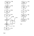
- FIG. 1 shows a flow chart of the steps that are carried out at the entrance control according to a preferred embodiment of the method according to the invention in order to check vehicles in car parks.
- the vehicle is driven into the entrance lock, so that it is located between a front and a rear barrier.
- an image is recorded of the vehicle using a digital camera, such as for example a CCD (charge-coupled device) camera.
- the camera is mounted in such a way that it can record images of the vehicle's rear registration plate and rear lights.
- an infrared illumination unit provided with infrared light-emitting diodes is mounted in the vicinity of the camera to illuminate the registration plate and the rear lights.
- Images can be recorded both with and without infrared illumination, in order to obtain measurement results that are independent of the general lighting.
- a control unit preferably a PC
- the PC is connected to a server or the like for storing the results of the analysis
- the PC or the server is provided with analysis software.
- This software comprises programs for position determination of the registration plate by means of the images, and a system that extracts the registration number from a camera image.
- the analysis can also comprise determination of the model of car and of the position of the tax mark.
- the results of the analysis are stored in the server, whereby a code is created that gives access to the results of the analysis.
- step 108 the driver of the vehicle receives a car park ticket, provided with the code, from a ticket printing machine.
- the ticket printing machine is located beside the lock and is connected to the control unit. If required, the car park ticket can also be provided with a picture of the vehicle.
- FIG. 2 illustrates the steps that are carried out when the vehicle leaves, according to the preferred embodiment of the invention.
- step 200 the driver has retrieved his vehicle and driven into the exit lock. This is designed in a similar way to the entrance lock, with a digital camera, an infrared illumination unit and a PC connected to a server. However, it is provided with a ticket reader instead of a ticket printer, for reading the driver's car park ticket, according to step 202.
- step 204 an image is recorded with infrared illumination, as in step 102 at the entrance, while the vehicle is located between a front and a rear barrier.
- step 206 the same analyzes are carried out as at the entrance, that is primarily a precise position determination of the vehicle's registration plate and rear lights, using the infrared illumination that is reflected from the plate and the rear lights, and determination of the vehicle's registration number.
- step 208 it is checked that payment has been received for the parking, and if this is the case, in a step 210, a comparison is then carried out between the results of the analyzes from step 206 and the driver's stored analysis results from step 104 at the entrance, which the PC can read off by means of the code on the car park ticket.
- step 214 the car is allowed to leave by the front barrier being raised, if the comparison in step 210 showed that the vehicle that the driver intends to drive out is the same vehicle as the one that he drove in. As a result of only the front barrier being raised, so-called tailgating is prevented, that is an additional vehicle being driven out straight after the first.
- step 212 the vehicle is instead to be prevented from leaving, and the barriers are not raised, but instead a park attendant is notified. The attendant can then carry out a manual check of the driver's identity and the identity of the vehicle, and can allow the vehicle to leave or can call the police.
- no car park ticket is printed out. Instead an account card belonging to the driver is used, with information on this being able to be linked to the stored analysis results for the parked vehicle.
- Figure 3a illustrates the arrangement according to the invention for checking vehicles in a car park.
- a vehicle that is to be parked is driven into the entrance lock 300.
- There images are recorded of the vehicle's registration plate and rear lights using a digital camera 301.
- the car can be illuminated by an infrared illumination unit 302, mounted close to the digital camera, whereby images can be recorded with the infrared illumination switched on.
- Analyzes of the images are then carried out by a computer 303, after which the results are stored in a server 304, together with a link to the driver of the vehicle, by the driver obtaining a car park ticket that gives access to the results of the analyzes, or by information from an account card that belongs to the driver being stored together with the results of the analyzes.
- a vehicle that is to be retrieved from the car park is driven into the exit lock 305 where images are recorded of the vehicle by means of a digital camera 306, while at the same time, if required, the vehicle is illuminated by an infrared illumination unit 307.
- Analyzes are carried out in a computer 308, after which the results of the analyzes are compared with the results which were obtained when the vehicle entered the car park and which are stored in the server. If the comparison shows that the driver intends to drive out the same vehicle that he drove in, the front barrier 309 is raised, so that the vehicle is allowed to leave.
- Figure 3b shows schematically a vehicle lock in a view from above according to an embodiment of the invention comprising an entrance control 300 and an exit control 305.
- the entrance and exit controls work in the same way.
- a first vehicle 310 is on its way out from the entrance control and a second vehicle 311 is waiting to be able to enter the entrance control 300.
- An entry barrier 312 prevents the first vehicle 311 from coming into the entrance control 300 while the first vehicle 310 is driving out.
- the first vehicle is allowed to drive out by the removal of an exit barrier 313.
- the entry and exit barriers consist of barriers that are raised and lowered.
- a third vehicle 315 is on its way into the exit control 305.
- first and second ticket machines 316 and 317 comprising for example thermal printers, are arranged to issue or receive tickets, or other forms of identification, for example credit cards, in order to identify the vehicle.
- cameras are arranged to photograph the vehicle and at least one computer and database are arranged to carry out an analysis and to store results, in order in this way to be able to carry out the identification as discussed above and below.
- the method for checking vehicles thus comprises steps of identifying a vehicle by recording images 102, 204 and by analysis 104, 206 of images at an entrance control and at an exit control.
- the images and/or the analysis results from the entrance control are stored 106 and a comparison 210 is carried out of the analysis results from the exit control with the stored analysis results from the entrance control.
- the vehicle is prevented 212 or allowed 214 to leave.
- the vehicle is admitted to the exit control by the vehicle being driven forwards 200 to a front exit barrier at the exit control.
- a rear exit barrier is then set up behind the vehicle, so that additional vehicles are prevented from entering the exit control and so that the vehicle cannot reverse out. If the comparison above is positive, that is if the vehicle is to be allowed to leave the control, the front exit barrier is removed, whereby other vehicles are prevented by the rear exit barrier from driving through the exit control at the same time as the vehicle.
- the entrance control also comprises a front and a rear exit barrier.
- the vehicle is driven forwards to the front exit barrier and the rear exit barrier is set up behind the vehicle.
- the front exit barrier is then removed when the vehicle is to be allowed to pass through, whereby other vehicles are prevented from driving through the entrance control at the same time as the vehicle.
- the entrance control can only comprise a front barrier.
- the front exit barrier is set up again after the vehicle has passed and the rear exit barrier is not removed until after the front exit barrier has been set up again, so that further vehicles can drive into the said passage control.
- the front and rear exit barriers can be barriers that are lowered and raised or raised and lowered automatically in order to prevent or allow the passage of vehicles.
- the analysis comprises identifying the position and orientation on the car of at least one light arrangement and of determining what type of car is in the passage control on the basis of information stored in a database relating to the position and orientation of light arrangements on different types of cars and the said identification of the position and orientation of the said light arrangement. Comparing an analysis result in order just to be able to identify the type of vehicle on the basis of a database of vehicles requires only a relatively rough analysis of the image.
- the analysis also comprises identifying the position on the car and the orientation of the registration plate in relation to the identified position of the light arrangement by image analysis of the image in order thereby to obtain a unique identification of the said vehicle. By first identifying the type of car and then analyzing the position and orientation of the registration plate with knowledge of the type of car that the registration plate is attached to, an excellent and precise result is obtained. By this means, the car can be uniquely identified.
Landscapes
- Physics & Mathematics (AREA)
- Engineering & Computer Science (AREA)
- General Physics & Mathematics (AREA)
- Architecture (AREA)
- Finance (AREA)
- Business, Economics & Management (AREA)
- Toxicology (AREA)
- Electromagnetism (AREA)
- Computer Vision & Pattern Recognition (AREA)
- Theoretical Computer Science (AREA)
- General Health & Medical Sciences (AREA)
- Civil Engineering (AREA)
- Structural Engineering (AREA)
- Artificial Intelligence (AREA)
- Health & Medical Sciences (AREA)
- Traffic Control Systems (AREA)
- Devices For Checking Fares Or Tickets At Control Points (AREA)
- Length Measuring Devices By Optical Means (AREA)
- Transition And Organic Metals Composition Catalysts For Addition Polymerization (AREA)
- Plural Heterocyclic Compounds (AREA)
- Pharmaceuticals Containing Other Organic And Inorganic Compounds (AREA)
- Lighting Device Outwards From Vehicle And Optical Signal (AREA)
Claims (10)
- Procédé pour contrôler les véhicules dans un parc de stationnement comprenant l'identification d'un véhicule par enregistrement d'images (102, 204) et l'analyse (104, 206) dudit véhicule à un contrôle à l'entrée et à un contrôle à la sortie, stockage (106) des résultats d'analyse provenant du contrôle à l'entrée, comparaison (210) des résultats d'analyse provenant du contrôle à la sortie avec les résultats d'analyse provenant du contrôle à l'entrée précédemment stockés et interdiction (212) ou permission (214) au véhicule de partir, caractérisé en ce que- au contrôle à la sortie, ledit véhicule est avancé (200) jusqu'à une barrière de sortie avant,- une barrière de sortie arrière s'abaisse derrière ledit véhicule,- ladite analyse (104, 206) implique d'identifier, sur au moins une desdites images prises au contrôle à l'entrée et au moins une desdites images prises au contrôle à la sortie, la position d'au moins un dispositif réflecteur sur ledit véhicule,- ladite comparaison (210) implique de comparer ledit dispositif réflecteur identifié, et- ladite barrière de sortie avant ne sera levée que quand le véhicule sera autorisé (214) à partir, moyennant quoi d'autres véhicules seront empêchés de traverser le contrôle à la sortie en même temps que ledit véhicule.
- Procédé selon la revendication 1, caractérisé en ce que- ledit contrôle à l'entrée comprend une barrière de sortie avant et une barrière de sortie arrière,- au contrôle à l'entrée, ledit véhicule est avancé jusqu'à ladite barrière de sortie avant,- ladite barrière de sortie arrière s'abaisse derrière ledit véhicule, et- ladite barrière de sortie avant ne sera levée que quand le véhicule sera autorisé à traverser, moyennant quoi d'autres véhicules sont empêchés de traverser le contrôle à l'entrée en même temps que ledit véhicule.
- Procédé selon la revendication 1 ou 2, comprenant les étapes consistant à- abaisser à nouveau ladite barrière de sortie avant après que ledit véhicule ait traversé,- relever ladite barrière de sortie arrière après que ladite barrière de sortie avant ait été à nouveau abaissée afin de permettre à un autre véhicule d'entrer dans ledit contrôle de passage.
- Procédé selon l'une quelconque des revendications 1 à 3, caractérisé en ce que ladite barrière de sortie avant et ladite barrière de sortie arrière sont des barrières qui s'abaissent et se relèvent ou se relèvent et s'abaissent automatiquement afin d'empêcher ou de permettre le passage de véhicules.
- Procédé selon l'une quelconque des revendications 1 à 4, caractérisé en ce qu'un reçu créé au contrôle à l'entrée constitue un code qui est créé pendant le stockage (106) des résultats de l'analyse et imprimé sur un ticket (108) de parc de stationnement pour le conducteur du véhicule, à utiliser par le conducteur quand il paiera pour le stationnement et au contrôle à la sortie (202).
- Procédé selon la revendication 5, caractérisé en ce que le reçu consiste en l'enregistrement d'un code, obtenu par exemple à partir d'une carte bancaire ou d'une carte de crédit présentée par le conducteur du véhicule, ainsi que les résultats d'analyse provenant du contrôle à l'entrée.
- Procédé selon l'une quelconque des revendications 1 à 6, caractérisé en ce que ladite analyse comprend- l'identification de la position et de l'orientation sur la voiture d'au moins une disposition lumineuse au moyen de ladite analyse dudit enregistrement d'images,- la détermination du type de véhicule sur la base des informations stockées dans une base de données concernant la position et l'orientation des dispositions lumineuses sur différents types de voitures et de ladite identification de la position et de l'orientation de ladite disposition lumineuse,- l'identification de la position sur la voiture et de l'orientation de ladite plaque d'immatriculation par rapport à la position de ladite disposition lumineuse identifiée au moyen de ladite analyse d'image de ladite première image afin d'obtenir de ce fait une identification unique dudit véhicule.
- Sas à véhicule dans un parc de stationnement disposé pour permettre aux véhicules de passer de façon sécurisée d'une première zone à une seconde zone,
caractérisé en ce que- une barrière d'entrée est disposée pour, dans une première position, interdire l'entrée dans ledit sas à véhicule et, dans une seconde position, autoriser l'entrée dans ledit sas à véhicule,- une barrière de sortie est disposée pour, dans une première position, interdire la sortie dudit sas à véhicule et, dans une seconde position, autoriser la sortie dudit sas à véhicule,- ladite barrière d'entrée étant disposée pour interdire l'entrée dans ledit sas à véhicule quand ladite barrière de sortie autorise la sortie dudit sas à véhicule, et- ladite barrière de sortie étant disposée pour interdire la sortie dudit sas à véhicule quand ladite barrière d'entrée autorise l'entrée dans ledit sas à véhicule, et- un dispositif d'identification est mis en place pour identifier la position d'au moins un dispositif réflecteur sur ledit véhicule et la position dudit dispositif réflecteur est utilisée pour déterminer si le véhicule est autorisé à traverser ledit sas à véhicule. - Système de contrôle de circulation pour contrôler l'entrée de véhicules d'une zone extérieure à une zone intérieure et la sortie de ladite zone intérieure à ladite zone extérieure, caractérisé en ce que
l'entrée dans ladite zone intérieure et la sortie de celle-ci se font au moyen d'au moins une route et un sas à véhicule selon la revendication 8 est disposé pour contrôler les véhicules qui passent sur ladite route. - Système de contrôle de circulation selon la revendication 9, caractérisé en ce qu'un premier sas à véhicule est disposé pour contrôler les véhicules qui entrent dans ladite zone intérieure sur une route d'entrée et qu'un second sas à véhicule est disposé pour contrôler les véhicules qui quittent ladite zone intérieure sur une route de sortie, lesdits premier et second sas à véhicule étant des sas à véhicule selon la revendication 8.
Applications Claiming Priority (3)
| Application Number | Priority Date | Filing Date | Title |
|---|---|---|---|
| SE0300221A SE531334C2 (sv) | 2003-01-30 | 2003-01-30 | Fordon ID |
| SE0300221 | 2003-01-30 | ||
| PCT/SE2004/000115 WO2004068417A1 (fr) | 2003-01-30 | 2004-01-29 | Identification de vehicule |
Publications (2)
| Publication Number | Publication Date |
|---|---|
| EP1588330A1 EP1588330A1 (fr) | 2005-10-26 |
| EP1588330B1 true EP1588330B1 (fr) | 2009-04-15 |
Family
ID=20290242
Family Applications (1)
| Application Number | Title | Priority Date | Filing Date |
|---|---|---|---|
| EP04706403A Expired - Lifetime EP1588330B1 (fr) | 2003-01-30 | 2004-01-29 | Identification de vehicule |
Country Status (8)
| Country | Link |
|---|---|
| US (1) | US7471189B2 (fr) |
| EP (1) | EP1588330B1 (fr) |
| AT (1) | ATE429000T1 (fr) |
| DE (1) | DE602004020582D1 (fr) |
| DK (1) | DK1588330T3 (fr) |
| ES (1) | ES2325439T3 (fr) |
| SE (1) | SE531334C2 (fr) |
| WO (1) | WO2004068417A1 (fr) |
Families Citing this family (37)
| Publication number | Priority date | Publication date | Assignee | Title |
|---|---|---|---|---|
| US20040167861A1 (en) * | 2003-02-21 | 2004-08-26 | Hedley Jay E. | Electronic toll management |
| US10878646B2 (en) | 2005-12-08 | 2020-12-29 | Smartdrive Systems, Inc. | Vehicle event recorder systems |
| US20070150138A1 (en) | 2005-12-08 | 2007-06-28 | James Plante | Memory management in event recording systems |
| US8996240B2 (en) | 2006-03-16 | 2015-03-31 | Smartdrive Systems, Inc. | Vehicle event recorders with integrated web server |
| US9201842B2 (en) | 2006-03-16 | 2015-12-01 | Smartdrive Systems, Inc. | Vehicle event recorder systems and networks having integrated cellular wireless communications systems |
| US8269617B2 (en) * | 2009-01-26 | 2012-09-18 | Drivecam, Inc. | Method and system for tuning the effect of vehicle characteristics on risk prediction |
| US8508353B2 (en) | 2009-01-26 | 2013-08-13 | Drivecam, Inc. | Driver risk assessment system and method having calibrating automatic event scoring |
| US8849501B2 (en) | 2009-01-26 | 2014-09-30 | Lytx, Inc. | Driver risk assessment system and method employing selectively automatic event scoring |
| US8384555B2 (en) * | 2006-08-11 | 2013-02-26 | Michael Rosen | Method and system for automated detection of mobile phone usage |
| US8989959B2 (en) | 2006-11-07 | 2015-03-24 | Smartdrive Systems, Inc. | Vehicle operator performance history recording, scoring and reporting systems |
| US8649933B2 (en) | 2006-11-07 | 2014-02-11 | Smartdrive Systems Inc. | Power management systems for automotive video event recorders |
| US8868288B2 (en) | 2006-11-09 | 2014-10-21 | Smartdrive Systems, Inc. | Vehicle exception event management systems |
| US8239092B2 (en) | 2007-05-08 | 2012-08-07 | Smartdrive Systems Inc. | Distributed vehicle event recorder systems having a portable memory data transfer system |
| US8050963B2 (en) * | 2008-02-26 | 2011-11-01 | Burdick Joshua H | Method of assessing a parking fee |
| US8335711B2 (en) * | 2008-02-26 | 2012-12-18 | Burdick Joshua H | Method of assessing a parking fee based upon vehicle make and model |
| US20110313822A1 (en) * | 2008-02-26 | 2011-12-22 | Joshua Burdick | Method of Assessing Parking Fees Based Upon Vehicle Length |
| US8854199B2 (en) | 2009-01-26 | 2014-10-07 | Lytx, Inc. | Driver risk assessment system and method employing automated driver log |
| US8311343B2 (en) * | 2009-02-12 | 2012-11-13 | Laser Technology, Inc. | Vehicle classification by image processing with laser range finder |
| US9728228B2 (en) | 2012-08-10 | 2017-08-08 | Smartdrive Systems, Inc. | Vehicle event playback apparatus and methods |
| US9501878B2 (en) | 2013-10-16 | 2016-11-22 | Smartdrive Systems, Inc. | Vehicle event playback apparatus and methods |
| US9610955B2 (en) | 2013-11-11 | 2017-04-04 | Smartdrive Systems, Inc. | Vehicle fuel consumption monitor and feedback systems |
| KR20150076532A (ko) * | 2013-12-27 | 2015-07-07 | 주식회사 만도 | 차량 거리 측정 시스템 및 그를 위한 방법 |
| US8892310B1 (en) | 2014-02-21 | 2014-11-18 | Smartdrive Systems, Inc. | System and method to detect execution of driving maneuvers |
| US9663127B2 (en) | 2014-10-28 | 2017-05-30 | Smartdrive Systems, Inc. | Rail vehicle event detection and recording system |
| KR101521457B1 (ko) * | 2014-11-03 | 2015-05-22 | 주식회사 넥스파시스템 | 영상방식을 이용한 지상주차장의 차량 위치 확인 시스템 및 그 제어방법 |
| US11069257B2 (en) | 2014-11-13 | 2021-07-20 | Smartdrive Systems, Inc. | System and method for detecting a vehicle event and generating review criteria |
| FR3028535B1 (fr) * | 2014-11-14 | 2016-11-11 | La Barriere Automatique | Dispositif de fermeture automatique d’une voie de circulation |
| US9679420B2 (en) | 2015-04-01 | 2017-06-13 | Smartdrive Systems, Inc. | Vehicle event recording system and method |
| US10049286B2 (en) * | 2015-12-15 | 2018-08-14 | International Business Machines Corporation | Image-based risk estimation |
| US11055942B2 (en) | 2017-08-01 | 2021-07-06 | The Chamberlain Group, Inc. | System and method for facilitating access to a secured area |
| WO2019028039A1 (fr) | 2017-08-01 | 2019-02-07 | The Chamberlain Group, Inc. | Système pour faciliter l'accès à une zone sécurisée |
| TWI637357B (zh) * | 2017-09-13 | 2018-10-01 | 緯創資通股份有限公司 | 管理停車場的方法及系統 |
| CN107993447A (zh) * | 2017-12-12 | 2018-05-04 | 西安艾润物联网技术服务有限责任公司 | 车辆非法通行解决方法、装置及可读存储介质 |
| CN110555998A (zh) * | 2019-06-04 | 2019-12-10 | 恒大智慧科技有限公司 | 一种车位锁联动方法及系统 |
| US11436836B2 (en) | 2019-06-28 | 2022-09-06 | Ricardo Ernesto Ramirez | Vehicular access security system |
| CN110942639A (zh) * | 2019-10-22 | 2020-03-31 | 安信通科技(澳门)有限公司 | 一种停车场闸机控制方法及系统 |
| FR3106111B1 (fr) * | 2020-01-15 | 2022-01-21 | Psa Automobiles Sa | Procédé et dispositif de contrôle d’un véhicule |
Family Cites Families (16)
| Publication number | Priority date | Publication date | Assignee | Title |
|---|---|---|---|---|
| US4507654A (en) * | 1981-10-30 | 1985-03-26 | A. R. F. Products | Security system with infrared optical position detector |
| US4603390A (en) | 1984-03-05 | 1986-07-29 | Soft Plus Corp. | Computerized parking system |
| GB2217498B (en) * | 1988-04-18 | 1992-03-18 | Ind Tech Res Inst | Method and apparatus for automatically recognising licence plate characters |
| JPH01319898A (ja) * | 1988-06-21 | 1989-12-26 | Mitsubishi Electric Corp | 料金徴収装置 |
| CA2132515C (fr) * | 1992-03-20 | 2006-01-31 | Glen William Auty | Systeme de surveillance d'objets |
| JPH097014A (ja) | 1995-06-23 | 1997-01-10 | Matsushita Electric Ind Co Ltd | 駐車場管理システム及びこれに用いる装置 |
| US5568406A (en) * | 1995-12-01 | 1996-10-22 | Gerber; Eliot S. | Stolen car detection system and method |
| JP3206414B2 (ja) * | 1996-01-10 | 2001-09-10 | トヨタ自動車株式会社 | 車種判別装置 |
| JPH09296621A (ja) | 1996-05-01 | 1997-11-18 | Shinko Electric Co Ltd | 駐輪場ゲート |
| US5734343A (en) * | 1996-07-18 | 1998-03-31 | Motorola, Inc. | One-way optical highway communication system |
| US6281928B1 (en) * | 1998-05-13 | 2001-08-28 | Chuo Hatsujo Kabushiki Kaisha | Positional detector device for a vehicular license plate |
| US6411215B1 (en) * | 1999-02-19 | 2002-06-25 | J. Mitchell Shnier | Optical methods for detecting the position or state of an object |
| KR100319548B1 (ko) * | 1999-03-22 | 2002-01-05 | 김재한 | 게이트 통과 객체의 방향 검출 및 통보 장치 |
| US6650765B1 (en) * | 2000-01-11 | 2003-11-18 | Pulnix America, Inc. | System for simultaneously imaging vehicles and their license plates |
| JP3987264B2 (ja) * | 2000-03-24 | 2007-10-03 | 富士通株式会社 | ナンバープレート読取装置及び方法 |
| US6832728B2 (en) * | 2001-03-26 | 2004-12-21 | Pips Technology, Inc. | Remote indicia reading system |
-
2003
- 2003-01-30 SE SE0300221A patent/SE531334C2/sv unknown
-
2004
- 2004-01-29 ES ES04706403T patent/ES2325439T3/es not_active Expired - Lifetime
- 2004-01-29 DE DE602004020582T patent/DE602004020582D1/de not_active Expired - Lifetime
- 2004-01-29 AT AT04706403T patent/ATE429000T1/de active
- 2004-01-29 US US10/543,700 patent/US7471189B2/en not_active Expired - Fee Related
- 2004-01-29 DK DK04706403T patent/DK1588330T3/da active
- 2004-01-29 EP EP04706403A patent/EP1588330B1/fr not_active Expired - Lifetime
- 2004-01-29 WO PCT/SE2004/000115 patent/WO2004068417A1/fr not_active Ceased
Also Published As
| Publication number | Publication date |
|---|---|
| ATE429000T1 (de) | 2009-05-15 |
| SE0300221D0 (sv) | 2003-01-30 |
| SE0300221L (sv) | 2004-07-31 |
| US20060232442A1 (en) | 2006-10-19 |
| WO2004068417A1 (fr) | 2004-08-12 |
| US7471189B2 (en) | 2008-12-30 |
| DE602004020582D1 (de) | 2009-05-28 |
| SE531334C2 (sv) | 2009-02-24 |
| DK1588330T3 (da) | 2009-08-10 |
| EP1588330A1 (fr) | 2005-10-26 |
| ES2325439T3 (es) | 2009-09-04 |
Similar Documents
| Publication | Publication Date | Title |
|---|---|---|
| US7471189B2 (en) | Vehicle id | |
| CN112837560B (zh) | 一种基于5g的新型智能化公共停车场智能管理方法 | |
| US5859415A (en) | Method and apparatus for the registration of a vehicle(s) in a free flow toll facility by tracking the vehicle along a path in the toll facility area | |
| US5638302A (en) | System and method for preventing auto thefts from parking areas | |
| US5554984A (en) | Electronic traffic tariff reception system and vehicle identification apparatus | |
| US6459386B1 (en) | Parking violation recording system | |
| US6868313B2 (en) | Automobile license tag scanning system | |
| KR101978368B1 (ko) | 영상 송출을 활용한 장애인 주차구역 실시간 관리 방법 및 시스템 | |
| US20050228715A1 (en) | Management system for a parking site for vehicles | |
| CN103065470A (zh) | 基于单目多检测面的机器视觉的车辆闯红灯行为检测装置 | |
| WO2008027221A2 (fr) | Procede et systeme permettant d'ameliorer la fluidite de la circulation | |
| AU2017204377A1 (en) | Vehicle parking | |
| US6084532A (en) | System for the control and monitoring of light vehicle transit in public car parks | |
| US20060208924A1 (en) | Apparatus and method for controlling moving vehicles | |
| KR20050003664A (ko) | 차대 촬영장치 및 이를 이용한 출입차량의 통제 시스템 | |
| CN215814513U (zh) | 电动自行车违章取证系统 | |
| EP0565014A1 (fr) | Système de reconnaissance des véhicules pour parkings ou similaires | |
| JPH11306484A (ja) | 無人駐車場の車種別管理システム | |
| NZ500162A (en) | Computer controlled car park, computer stores images of car including license number on vehicle entry | |
| CN109377768B (zh) | 一种用于路边停车的停车检测方法及系统 | |
| JP7228314B2 (ja) | フラップレス駐車場の不正出庫車検出システム | |
| GB2405980A (en) | Car park security system with image data on ticket | |
| WO2000060544A1 (fr) | Dispositif d'impression de ticket de stationnement | |
| JPH11259707A (ja) | 料金収受システム及び料金収受方法 | |
| KR20190061543A (ko) | 자동 화물 반출입 시스템 중 셔틀 내 화물 정렬 방법 |
Legal Events
| Date | Code | Title | Description |
|---|---|---|---|
| PUAI | Public reference made under article 153(3) epc to a published international application that has entered the european phase |
Free format text: ORIGINAL CODE: 0009012 |
|
| 17P | Request for examination filed |
Effective date: 20050816 |
|
| AK | Designated contracting states |
Kind code of ref document: A1 Designated state(s): AT BE BG CH CY CZ DE DK EE ES FI FR GB GR HU IE IT LI LU MC NL PT RO SE SI SK TR |
|
| AX | Request for extension of the european patent |
Extension state: AL LT LV MK |
|
| DAX | Request for extension of the european patent (deleted) | ||
| GRAP | Despatch of communication of intention to grant a patent |
Free format text: ORIGINAL CODE: EPIDOSNIGR1 |
|
| RIN1 | Information on inventor provided before grant (corrected) |
Inventor name: HAELLBERG, JESPER Inventor name: VASTAD, FREDRIK |
|
| GRAS | Grant fee paid |
Free format text: ORIGINAL CODE: EPIDOSNIGR3 |
|
| GRAA | (expected) grant |
Free format text: ORIGINAL CODE: 0009210 |
|
| AK | Designated contracting states |
Kind code of ref document: B1 Designated state(s): AT BE BG CH CY CZ DE DK EE ES FI FR GB GR HU IE IT LI LU MC NL PT RO SE SI SK TR |
|
| REG | Reference to a national code |
Ref country code: CH Ref legal event code: EP Ref country code: GB Ref legal event code: FG4D |
|
| REG | Reference to a national code |
Ref country code: IE Ref legal event code: FG4D |
|
| REF | Corresponds to: |
Ref document number: 602004020582 Country of ref document: DE Date of ref document: 20090528 Kind code of ref document: P |
|
| REG | Reference to a national code |
Ref country code: CH Ref legal event code: NV Representative=s name: BOHEST AG |
|
| REG | Reference to a national code |
Ref country code: DK Ref legal event code: T3 |
|
| REG | Reference to a national code |
Ref country code: ES Ref legal event code: FG2A Ref document number: 2325439 Country of ref document: ES Kind code of ref document: T3 |
|
| PG25 | Lapsed in a contracting state [announced via postgrant information from national office to epo] |
Ref country code: PT Free format text: LAPSE BECAUSE OF FAILURE TO SUBMIT A TRANSLATION OF THE DESCRIPTION OR TO PAY THE FEE WITHIN THE PRESCRIBED TIME-LIMIT Effective date: 20090915 |
|
| PG25 | Lapsed in a contracting state [announced via postgrant information from national office to epo] |
Ref country code: SI Free format text: LAPSE BECAUSE OF FAILURE TO SUBMIT A TRANSLATION OF THE DESCRIPTION OR TO PAY THE FEE WITHIN THE PRESCRIBED TIME-LIMIT Effective date: 20090415 Ref country code: SE Free format text: LAPSE BECAUSE OF FAILURE TO SUBMIT A TRANSLATION OF THE DESCRIPTION OR TO PAY THE FEE WITHIN THE PRESCRIBED TIME-LIMIT Effective date: 20090715 |
|
| PG25 | Lapsed in a contracting state [announced via postgrant information from national office to epo] |
Ref country code: RO Free format text: LAPSE BECAUSE OF FAILURE TO SUBMIT A TRANSLATION OF THE DESCRIPTION OR TO PAY THE FEE WITHIN THE PRESCRIBED TIME-LIMIT Effective date: 20090415 Ref country code: EE Free format text: LAPSE BECAUSE OF FAILURE TO SUBMIT A TRANSLATION OF THE DESCRIPTION OR TO PAY THE FEE WITHIN THE PRESCRIBED TIME-LIMIT Effective date: 20090415 Ref country code: CZ Free format text: LAPSE BECAUSE OF FAILURE TO SUBMIT A TRANSLATION OF THE DESCRIPTION OR TO PAY THE FEE WITHIN THE PRESCRIBED TIME-LIMIT Effective date: 20090415 |
|
| PLBE | No opposition filed within time limit |
Free format text: ORIGINAL CODE: 0009261 |
|
| STAA | Information on the status of an ep patent application or granted ep patent |
Free format text: STATUS: NO OPPOSITION FILED WITHIN TIME LIMIT |
|
| PG25 | Lapsed in a contracting state [announced via postgrant information from national office to epo] |
Ref country code: SK Free format text: LAPSE BECAUSE OF FAILURE TO SUBMIT A TRANSLATION OF THE DESCRIPTION OR TO PAY THE FEE WITHIN THE PRESCRIBED TIME-LIMIT Effective date: 20090415 |
|
| 26N | No opposition filed |
Effective date: 20100118 |
|
| PG25 | Lapsed in a contracting state [announced via postgrant information from national office to epo] |
Ref country code: BG Free format text: LAPSE BECAUSE OF FAILURE TO SUBMIT A TRANSLATION OF THE DESCRIPTION OR TO PAY THE FEE WITHIN THE PRESCRIBED TIME-LIMIT Effective date: 20090715 |
|
| PG25 | Lapsed in a contracting state [announced via postgrant information from national office to epo] |
Ref country code: MC Free format text: LAPSE BECAUSE OF NON-PAYMENT OF DUE FEES Effective date: 20100131 |
|
| PG25 | Lapsed in a contracting state [announced via postgrant information from national office to epo] |
Ref country code: GR Free format text: LAPSE BECAUSE OF FAILURE TO SUBMIT A TRANSLATION OF THE DESCRIPTION OR TO PAY THE FEE WITHIN THE PRESCRIBED TIME-LIMIT Effective date: 20090716 |
|
| PG25 | Lapsed in a contracting state [announced via postgrant information from national office to epo] |
Ref country code: IE Free format text: LAPSE BECAUSE OF NON-PAYMENT OF DUE FEES Effective date: 20100129 |
|
| PG25 | Lapsed in a contracting state [announced via postgrant information from national office to epo] |
Ref country code: CY Free format text: LAPSE BECAUSE OF FAILURE TO SUBMIT A TRANSLATION OF THE DESCRIPTION OR TO PAY THE FEE WITHIN THE PRESCRIBED TIME-LIMIT Effective date: 20090415 |
|
| PG25 | Lapsed in a contracting state [announced via postgrant information from national office to epo] |
Ref country code: LU Free format text: LAPSE BECAUSE OF NON-PAYMENT OF DUE FEES Effective date: 20100129 Ref country code: HU Free format text: LAPSE BECAUSE OF FAILURE TO SUBMIT A TRANSLATION OF THE DESCRIPTION OR TO PAY THE FEE WITHIN THE PRESCRIBED TIME-LIMIT Effective date: 20091016 |
|
| PG25 | Lapsed in a contracting state [announced via postgrant information from national office to epo] |
Ref country code: TR Free format text: LAPSE BECAUSE OF FAILURE TO SUBMIT A TRANSLATION OF THE DESCRIPTION OR TO PAY THE FEE WITHIN THE PRESCRIBED TIME-LIMIT Effective date: 20090415 |
|
| PGFP | Annual fee paid to national office [announced via postgrant information from national office to epo] |
Ref country code: CH Payment date: 20140120 Year of fee payment: 11 Ref country code: BE Payment date: 20140120 Year of fee payment: 11 Ref country code: NL Payment date: 20140117 Year of fee payment: 11 Ref country code: DE Payment date: 20140121 Year of fee payment: 11 |
|
| PGFP | Annual fee paid to national office [announced via postgrant information from national office to epo] |
Ref country code: IT Payment date: 20140129 Year of fee payment: 11 Ref country code: FR Payment date: 20140131 Year of fee payment: 11 Ref country code: ES Payment date: 20140124 Year of fee payment: 11 Ref country code: AT Payment date: 20140129 Year of fee payment: 11 |
|
| PGFP | Annual fee paid to national office [announced via postgrant information from national office to epo] |
Ref country code: GB Payment date: 20140122 Year of fee payment: 11 |
|
| REG | Reference to a national code |
Ref country code: CH Ref legal event code: PCAR Free format text: NEW ADDRESS: HOLBEINSTRASSE 36-38, 4051 BASEL (CH) |
|
| PG25 | Lapsed in a contracting state [announced via postgrant information from national office to epo] |
Ref country code: BE Free format text: LAPSE BECAUSE OF NON-PAYMENT OF DUE FEES Effective date: 20150131 |
|
| REG | Reference to a national code |
Ref country code: DE Ref legal event code: R119 Ref document number: 602004020582 Country of ref document: DE |
|
| REG | Reference to a national code |
Ref country code: NL Ref legal event code: V1 Effective date: 20150801 |
|
| REG | Reference to a national code |
Ref country code: CH Ref legal event code: PL |
|
| REG | Reference to a national code |
Ref country code: AT Ref legal event code: MM01 Ref document number: 429000 Country of ref document: AT Kind code of ref document: T Effective date: 20150129 |
|
| GBPC | Gb: european patent ceased through non-payment of renewal fee |
Effective date: 20150129 |
|
| PG25 | Lapsed in a contracting state [announced via postgrant information from national office to epo] |
Ref country code: NL Free format text: LAPSE BECAUSE OF NON-PAYMENT OF DUE FEES Effective date: 20150801 |
|
| PG25 | Lapsed in a contracting state [announced via postgrant information from national office to epo] |
Ref country code: CH Free format text: LAPSE BECAUSE OF NON-PAYMENT OF DUE FEES Effective date: 20150131 Ref country code: LI Free format text: LAPSE BECAUSE OF NON-PAYMENT OF DUE FEES Effective date: 20150131 Ref country code: GB Free format text: LAPSE BECAUSE OF NON-PAYMENT OF DUE FEES Effective date: 20150129 Ref country code: DE Free format text: LAPSE BECAUSE OF NON-PAYMENT OF DUE FEES Effective date: 20150801 |
|
| REG | Reference to a national code |
Ref country code: FR Ref legal event code: ST Effective date: 20150930 |
|
| PG25 | Lapsed in a contracting state [announced via postgrant information from national office to epo] |
Ref country code: AT Free format text: LAPSE BECAUSE OF NON-PAYMENT OF DUE FEES Effective date: 20150129 Ref country code: FR Free format text: LAPSE BECAUSE OF NON-PAYMENT OF DUE FEES Effective date: 20150202 |
|
| PG25 | Lapsed in a contracting state [announced via postgrant information from national office to epo] |
Ref country code: IT Free format text: LAPSE BECAUSE OF NON-PAYMENT OF DUE FEES Effective date: 20150129 |
|
| REG | Reference to a national code |
Ref country code: ES Ref legal event code: FD2A Effective date: 20160826 |
|
| PGFP | Annual fee paid to national office [announced via postgrant information from national office to epo] |
Ref country code: FI Payment date: 20160725 Year of fee payment: 13 Ref country code: DK Payment date: 20160721 Year of fee payment: 13 |
|
| PG25 | Lapsed in a contracting state [announced via postgrant information from national office to epo] |
Ref country code: ES Free format text: LAPSE BECAUSE OF NON-PAYMENT OF DUE FEES Effective date: 20150130 |
|
| REG | Reference to a national code |
Ref country code: DK Ref legal event code: EBP Effective date: 20170131 |
|
| PG25 | Lapsed in a contracting state [announced via postgrant information from national office to epo] |
Ref country code: FI Free format text: LAPSE BECAUSE OF NON-PAYMENT OF DUE FEES Effective date: 20170129 |
|
| PG25 | Lapsed in a contracting state [announced via postgrant information from national office to epo] |
Ref country code: DK Free format text: LAPSE BECAUSE OF NON-PAYMENT OF DUE FEES Effective date: 20170131 |