EP1588587A9 - Farb-elektrolumineszenzdraht und verfahren zu seiner herstellung - Google Patents
Farb-elektrolumineszenzdraht und verfahren zu seiner herstellung Download PDFInfo
- Publication number
- EP1588587A9 EP1588587A9 EP03815513A EP03815513A EP1588587A9 EP 1588587 A9 EP1588587 A9 EP 1588587A9 EP 03815513 A EP03815513 A EP 03815513A EP 03815513 A EP03815513 A EP 03815513A EP 1588587 A9 EP1588587 A9 EP 1588587A9
- Authority
- EP
- European Patent Office
- Prior art keywords
- conductive
- casing tube
- wire
- light emitting
- layer
- Prior art date
- Legal status (The legal status is an assumption and is not a legal conclusion. Google has not performed a legal analysis and makes no representation as to the accuracy of the status listed.)
- Granted
Links
Images




Classifications
-
- H—ELECTRICITY
- H05—ELECTRIC TECHNIQUES NOT OTHERWISE PROVIDED FOR
- H05B—ELECTRIC HEATING; ELECTRIC LIGHT SOURCES NOT OTHERWISE PROVIDED FOR; CIRCUIT ARRANGEMENTS FOR ELECTRIC LIGHT SOURCES, IN GENERAL
- H05B33/00—Electroluminescent light sources
- H05B33/10—Apparatus or processes specially adapted to the manufacture of electroluminescent light sources
-
- H—ELECTRICITY
- H05—ELECTRIC TECHNIQUES NOT OTHERWISE PROVIDED FOR
- H05B—ELECTRIC HEATING; ELECTRIC LIGHT SOURCES NOT OTHERWISE PROVIDED FOR; CIRCUIT ARRANGEMENTS FOR ELECTRIC LIGHT SOURCES, IN GENERAL
- H05B33/00—Electroluminescent light sources
- H05B33/12—Light sources with substantially two-dimensional [2D] radiating surfaces
- H05B33/14—Light sources with substantially two-dimensional [2D] radiating surfaces characterised by the chemical or physical composition or the arrangement of the electroluminescent material, or by the simultaneous addition of the electroluminescent material in or onto the light source
- H05B33/145—Arrangements of the electroluminescent material
-
- H—ELECTRICITY
- H05—ELECTRIC TECHNIQUES NOT OTHERWISE PROVIDED FOR
- H05B—ELECTRIC HEATING; ELECTRIC LIGHT SOURCES NOT OTHERWISE PROVIDED FOR; CIRCUIT ARRANGEMENTS FOR ELECTRIC LIGHT SOURCES, IN GENERAL
- H05B33/00—Electroluminescent light sources
- H05B33/12—Light sources with substantially two-dimensional [2D] radiating surfaces
- H05B33/20—Light sources with substantially two-dimensional [2D] radiating surfaces characterised by the chemical or physical composition or the arrangement of the material in which the electroluminescent material is embedded
-
- H—ELECTRICITY
- H05—ELECTRIC TECHNIQUES NOT OTHERWISE PROVIDED FOR
- H05B—ELECTRIC HEATING; ELECTRIC LIGHT SOURCES NOT OTHERWISE PROVIDED FOR; CIRCUIT ARRANGEMENTS FOR ELECTRIC LIGHT SOURCES, IN GENERAL
- H05B33/00—Electroluminescent light sources
- H05B33/12—Light sources with substantially two-dimensional [2D] radiating surfaces
- H05B33/26—Light sources with substantially two-dimensional [2D] radiating surfaces characterised by the composition or arrangement of the conductive material used as an electrode
- H05B33/28—Light sources with substantially two-dimensional [2D] radiating surfaces characterised by the composition or arrangement of the conductive material used as an electrode of translucent electrodes
Definitions
- the present invention relates to an electroluminescent light source.
- it relates to an electroluminescent filament capable of emitting a plurality of colors as well as method and device for manufacturing the same.
- the conventional cable-like light emitting device mainly comprises: Neo light, with fragile glass outer layer, dangerous factors of high voltage and high frequency and incapability of being readily shaped, has the drawbacks of high power consumption and high cost for manufacture and maintenance.
- the colored incandescent light using filament to emit incandescent light and colored lamp-cover to achieve colored light effect consists of a plurality of small incandescent bulb or light emitting diode (LED);
- LED light emitting diode
- This kind of color tube is of substantial diameter and its diameter of lattice light filament is 10mm or more, and it is power-consuming, with its freedom of shaping being restricted by the large diameter and rigidity.
- the further drawbacks of said two devices lie in low efficiency in light emission, proneness to conductive wire damage and likelihood to cause fatal accidents when used in rainy weather.
- Still another electroluminescent light source also has its deficiency.
- the technical solution disclosed in the Patent No. CN1101125C and Patent No. US736021 relates to a mono-color light source using solvent to dilute the substance of electrolytic layers, making it loosely organized and producing a lot of blowholes and pores, which should be filled in with transparent substance for continuous light emission.
- the process is complex, and because transparent filler does not have a long, effective conductivity such that this kind of light source is apt to lose its function, the light emission can not last long, nor can the light be emitted evenly.
- One of the objects of the present invention is to overcome the drawbacks of the prior art and to provide an electroluminescent filament, low in electricity consumption, convenient to use and capable of emitting multiple colors and bright light, and a method and device for manufacturing the same.
- the present invention uses a squeezing coreless automatic orientation device which increases the structural density of the mixture of the layers of the present light-emitting filament, improves light emission efficiency and makes it unnecessary to use any transparent filler.
- the multi-colored, helical or sectional electroluminescent filament manufactured by the device of the present invention through the polymer placed on the out layer of the filament and composed of different colors, emitting 2 to 8 of colors which are helical or sectional pattern.
- a multi-colored electroluminescent filament comprising:
- Said transparent polymer casing tube is a protective layer protecting the transmission conductive wire from being broken and having a diameter ranging from 0.5 to 3mm.
- the diameter of said filament is in a range of 0.8 and 10mm.
- Said core wire a metal wire of a diameter ranging from 0.1 to 1mm, leads out an electrode.
- Said transmission conductive wires have at least one or more metal conductive wires that are highly conductive, specially treated and not easy to break; said metal conductive wires winds, at interval, round the outer side of the conductive layer and are led out as the other electrode.
- Said transmission conductive wires may have a diameter in the range of 0.04 and 0.12mm.
- Said medium insulating layer is a mixture coat of flexible binder having cyanoethyl as its base and BaTi03 powder, with its preferred thickness ranging from 25 ⁇ m to 60 ⁇ . m.
- Said light-emitting layer is a mixture coat of flexible binder having cyanoethyl as its base and luminescent phosphorus powder, with its preferred thickness ranging from 25 ⁇ m to 60 ⁇ m.
- Said conductive layer is a semi-transparent, highly conductive semi-solid viscous conductive substance, with its preferred thickness of 0.05mm or less.
- the preferred thickness of said three coats of the present invention is the result of a lot of experiments made by the present inventor, and has overcome the drawbacks of the electroluminescent filament of the prior art.
- the present inventor has concluded from much experimentation that where the input power supply is of an equivalent parameter, the thickness of the medium insulating layer and light emitting layer has a direct effect on the light emission and bend resistance of the light-emitting filament. If the thickness exceeds 60 ⁇ m, the light emitted by the light-emitting filament will be dimmer.
- the internal organization under the impact of the internal bending force, is broken after being increasingly compressed along with the decreasing of the diameter of the bending, which would result in short circuit of the light-emitting filament or break the medium insulating player and the light emitting layer, thus disabling the light emission or causing partial non-light-emission of the light emitting filament.
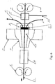
- Said coreless orientation squeezing automatic device is the most important device used in the production line for manufacturing the light emitting filament, mainly comprising the following members: two sets of rotary fixed wheels in the front and rare, air-tight box having an air pressure device, a spherical fixing-center-member, outer ring of the spherical fixing-center-member, sealing ring, pressure valve of the spherical fixing-center-member and dry box.
- Said device for covering polymer of a plurality of colors mainly comprises following members: a plurality of fixed leading wheels, cooling groove, traction wheel sets, multi-heating-path mould head, moving contactor, electric motor, speed-regulating wheel sets, control wires, program control stand, composite wheel disk and squeezing machine set having an electric motor on the composite wheel disk.
- the present invention is a multi-colored, helical or sectional light-emitting filament capable of being bent into a variety of shape and emitting at least 2 to 8 different colors.
- a multi-colored electroluminescent filament with helical colors pattern comprising:
- Core wire 1 a metal wire of a diameter 0.5 mm, is led out as an electrode.
- Said medium insulating layer 2 is a mixture coat of flexible binder having cyanoethyl as its base and BaTi03 powder, with a preferred thickness of 0.035mm.
- Said light-emitting layer 3 is a mixture coat of flexible binder having cyanoethyl as its base and light emitting phosphorus powder, with a preferred thickness of 0.035mm.
- Said conductive layer 4 is a semi-transparent, highly conductive semi-solid viscous conductive substance, with a preferred thickness of 0.05mm or less.
- Said transmission conductive wires 5, 5' are two metal conductive wires having a diameter of 0.06mm that are highly conductive, specially treated and not easy to break; the two metal wires wind, at interval, round the outer side of the conductive layer 4 and are led out as the other electrode.
- Transparent polymer casing tube 6 is a protective layer to protect transmission conductive wire 5, 5' from being broken.
- the coreless orientation squeezing automatic device is a production line, mainly comprising: two sets of rotary fixed wheels 9, 9' in the front and rare, air-tight box having an air pressure device 10, mixture material 17' contained in the box, air-pressure device tube 11, a spherical fixing-center-member 12, outer ring 13 of the spherical fixing-center-member, sealing ring 14, pressure valve 15 of the spherical fixing-center-member, air-pressure device tube of pressure valve 16, 16', mixture material 17 in the spherical fixing-center-member12 and a dry box 18.
- the process flow for manufacturing the electroluminescent filament with the helical colors pattern comprises the following steps:
- spherical fixing-center-member 12 is a semi-spherical body made of special material, with its central hole large at its entrance and narrow at its exit which is slightly larger than core wire 1, with one end of bigger aperture being placed air-pressure valve 15 and sealing ring 14 and air-pressure device tube of pressure valve 16, 16'; when core wire 1 is coated with material of enhanced density during the first feeding of material, its size is not accurate, and it is not dry, but viscous.
- core wire 1 forms wire 4A.
- wire 4A then goes through the process to be wound round with transmission conductive wire 5 and coated with transparent polymer tube 6: at the front end of the mould head for discharging material and a polymer squeezing machine, a device (which is not shown in the figures and is a known technology) which can be rotary and lead in two conductive wires 5, 5' is arranged, the rotary power winds the wires around wire 4A, after being wound, it enters the mould head for discharging material, being subject to the traction of the squeezing machine, while winding the transmission conductive wire, it is covered with the transparent polymer casing tube to form wire 6A.
- a device which is not shown in the figures and is a known technology
- the device for covering multi-colored polymer casing tube mainly comprises the following members: material squeezing machine set 20 having an electric motor on the composite wheel disks 19, several sets of fixed leading wheels 21, traction wheel set 22, cooling groove 23, multi-heating-path mould head 24 , eight-channel moving contactor 25, program control stand 26, electric motor 27, speed-regulating wheel sets 28, control wire 29, control wire 30, control wire 31.
- the process of the present invention for manufacturing helical, multi-colored polymer layer is as follows: after wire 6A is prepared, the eight sets of material squeezing machines 20 on the composite wheel disk 19 are pre-heated to an appropriate temperature, program control stand 26 initiates the rotation of traction wheel set 22 through control wire 29; wire 6A, controlled by fixed leading wheel 21, goes through composite wheel disk 19, multi-heating-path mould head 24 and cooling groove 23 and moves in the direction indicated by the arrow; then, electric motor 27 is turned on through program control stand 26 and control wire 29 to activate the interlocking rotation of speed-regulating wheel set 28 and composite wheel disk 19, and program control stand 26 starts, through control wire 29, eight-channel moving contactor 25 and eight sets of material squeezing machine 20 on composite wheel disk 19; in the meantime, multi-colored polymer is squeezed out from different angles, and simultaneously discharged through multi-heating-path mould head 24 to cause it to surround wire 6A, when wire 6A moves straight and composite wheel disk 19 rotates, a
- a multi-colored electroluminescent filament with sectional colors pattern comprising:
- Core wire 1 a metal wire having a diameter of 0.8mm, is led out as an electrode.
- Said medium insulating layer is a mixture coat of flexible binder having cyanoethyl as its base and BaTi03 powder, with a preferred thickness of 50 ⁇ m.
- Said light-emitting layer is a mixture coat of flexible binder having cyanoethyl as its base and light emitting phosphorus powder, with a preferred thickness of 50 ⁇ m.
- Said conductive layer is a semi-transparent, highly conductive, semi-solid viscous conductive substance, with a preferred thickness of 0.04mm or less.
- Said transmission conductive wires 5, 5' are two metal conductive wires having a diameter of 0.12mm that are highly conductive, specially treated and not easy to break; the two metal wires wind, at interval, round the outer side of the conductive layer 4 and led out as the other electrode.
- Transparent polymer casing tube 6 is a protective layer to protect transmission conductive wire 5 from being broken.
- the length of the different color in each section of filament 7 is 1 ⁇ 200cm.
- the process flow of the present invention for manufacturing multi-colored electroluminescent filament with sectional colors pattern comprises the following steps:
- the manufacture of the three coat layers inside the filament i.e., insulating layer, light emitting layer and conductive layer
- the production line comprising three sets of coreless orientation squeezing automatic devices.
- the structure of each of the insulating layer, light emitting layer and conductive layer requires two-to-five-recycling process to ensure their exact and even thickness.
- the squeezing-type coreless automatic orientation device and process A ⁇ F for multiple-coats of material are identical with the process for coating material a plurality of times as illustrated in embodiment 1; hence, it is not elaborated here.
- the device of the present invention for coating multi-colored polymer with sectional colors pattern is identical with embodiment 1.
- control wire 30 initiates, through program control stand 26, the rotation of traction wheel set 22; wire 6A, controlled by fixed leading wheel 21, goes through composite wheel disk 19, multi-heating-path mould head 24, cooling groove 23 and moves in the direction indicated by the arrow; then program control stand 26 starts eight-channel moving contactor 25 and a certain set of material squeezing machine 20 on composite wheel disk 19 through control wire 29; a certain color polymer is squeezed out from multi-heating-path mould head 24, to surround wire 6A; when a certain quantities of polymer is squeezed out, program control stand 26 orders said squeezing machine 20 to stop working through control wire 31, and meanwhile orders the next squeezing machine to initiate its operation and discharge polymer of another color; The polymer of the two colors connect each other; if it goes on like this, it is possible to discharge polymer of different colors, which is attached to wire 6A after being discharged from multi-heating-path mould head 24; and immediately
- the electroluminescent filament of the present invention is low in power consumption, free from heating and cannot be abnormally switched off, and has relatively long service life, with 4000-hour lighting time.
- the filament can be bent into a plurality of geometrical shapes as consumers demand, and it is beautiful and appealing, with a plurality of colors to choose from.
- the present invention can be used for external and internal housing and automobile decoration, and for external decoration for the purpose of advertisement, in entertainment places, and for toys, art and handicraft products and electric and electronic equipment.
Landscapes
- Engineering & Computer Science (AREA)
- Manufacturing & Machinery (AREA)
- Illuminated Signs And Luminous Advertising (AREA)
- Electroluminescent Light Sources (AREA)
- Extrusion Moulding Of Plastics Or The Like (AREA)
- Toys (AREA)
Applications Claiming Priority (3)
| Application Number | Priority Date | Filing Date | Title |
|---|---|---|---|
| CNU032368925U CN2599896Y (zh) | 2003-01-29 | 2003-01-29 | 一种多彩电致发光线 |
| CN03236892 | 2003-01-29 | ||
| PCT/CN2003/000662 WO2004068908A1 (fr) | 2003-01-29 | 2003-08-13 | Fil electroluminescent colore et procede de fabrication de ce fil |
Publications (4)
| Publication Number | Publication Date |
|---|---|
| EP1588587A1 EP1588587A1 (de) | 2005-10-26 |
| EP1588587A4 EP1588587A4 (de) | 2006-11-29 |
| EP1588587A9 true EP1588587A9 (de) | 2007-08-15 |
| EP1588587B1 EP1588587B1 (de) | 2009-07-22 |
Family
ID=29787508
Family Applications (1)
| Application Number | Title | Priority Date | Filing Date |
|---|---|---|---|
| EP03815513A Expired - Lifetime EP1588587B1 (de) | 2003-01-29 | 2003-08-13 | Farb-elektrolumineszenzdraht und verfahren zu seiner herstellung |
Country Status (7)
| Country | Link |
|---|---|
| US (1) | US7016577B2 (de) |
| EP (1) | EP1588587B1 (de) |
| CN (2) | CN2599896Y (de) |
| AT (1) | ATE437553T1 (de) |
| AU (1) | AU2003257790A1 (de) |
| DE (1) | DE60328529D1 (de) |
| WO (1) | WO2004068908A1 (de) |
Families Citing this family (8)
| Publication number | Priority date | Publication date | Assignee | Title |
|---|---|---|---|---|
| GB0420705D0 (en) * | 2004-09-17 | 2004-10-20 | Koninkl Philips Electronics Nv | A fibre or filament |
| GB0420809D0 (en) * | 2004-09-18 | 2004-10-20 | Koninkl Philips Electronics Nv | Elongated electro-optic device |
| CN100353815C (zh) * | 2004-12-30 | 2007-12-05 | 何文政 | 一种幻彩的电致发光线及其生产制造方法 |
| WO2007053977A1 (fr) * | 2005-11-10 | 2007-05-18 | Yongjiang Yin | Ligne d'énergie électrique luminescente agencée en sections |
| GB2433645A (en) * | 2005-12-13 | 2007-06-27 | Tenso Technologies Ltd | Durable electroluminescent fibre |
| CN101422078B (zh) * | 2006-04-12 | 2011-01-26 | Lg化学株式会社 | 有机发光二极管元件及其制备方法 |
| US7561060B2 (en) * | 2006-11-16 | 2009-07-14 | International Business Machines Corporation | Electroluminescent data cable identification and computer system diagnostics |
| GB2453748A (en) * | 2007-10-17 | 2009-04-22 | Han-Ming Lee | A semiconductor lamp |
Family Cites Families (9)
| Publication number | Priority date | Publication date | Assignee | Title |
|---|---|---|---|---|
| US5135591A (en) * | 1990-11-28 | 1992-08-04 | Precision Fabrics Group, Inc. | Process of making a phosphorescent fiber reinforced plastic article |
| IL104052A (en) * | 1992-12-10 | 1996-07-23 | Elam Electroluminescent Ind Lt | Neuronic light sources |
| JPH07235375A (ja) * | 1994-02-22 | 1995-09-05 | Yazaki Corp | 線状el発光体及びその製造方法 |
| US5753381A (en) * | 1995-12-22 | 1998-05-19 | Add Vision Inc | Electroluminescent filament |
| US5869930A (en) * | 1996-10-22 | 1999-02-09 | Elam-Electroluminescent Industries Ltd. | Electroluminescent light source with a mixture layer filled with a transparent filler substance |
| US6329083B1 (en) * | 1997-11-05 | 2001-12-11 | Nec Corporation | Organic electroluminescent device containing a benzoperylene compound |
| US6851818B2 (en) * | 2000-12-13 | 2005-02-08 | Teldor Wires & Cables Ltd. | Electroluminescent cable and mounting system therefor |
| CN1150801C (zh) * | 2001-10-24 | 2004-05-19 | 郑岩 | 电致发光丝线器件 |
| CN2523165Y (zh) * | 2002-01-11 | 2002-11-27 | 浙江天台天宇灯饰有限公司 | 一种el发光线 |
-
2003
- 2003-01-29 CN CNU032368925U patent/CN2599896Y/zh not_active Expired - Fee Related
- 2003-08-13 AU AU2003257790A patent/AU2003257790A1/en not_active Abandoned
- 2003-08-13 AT AT03815513T patent/ATE437553T1/de not_active IP Right Cessation
- 2003-08-13 CN CNB038002833A patent/CN1207940C/zh not_active Expired - Fee Related
- 2003-08-13 DE DE60328529T patent/DE60328529D1/de not_active Expired - Lifetime
- 2003-08-13 EP EP03815513A patent/EP1588587B1/de not_active Expired - Lifetime
- 2003-08-13 WO PCT/CN2003/000662 patent/WO2004068908A1/zh not_active Ceased
- 2003-12-10 US US10/733,530 patent/US7016577B2/en not_active Expired - Fee Related
Also Published As
| Publication number | Publication date |
|---|---|
| US20040145313A1 (en) | 2004-07-29 |
| AU2003257790A1 (en) | 2004-08-23 |
| ATE437553T1 (de) | 2009-08-15 |
| CN1509585A (zh) | 2004-06-30 |
| DE60328529D1 (de) | 2009-09-03 |
| EP1588587B1 (de) | 2009-07-22 |
| EP1588587A1 (de) | 2005-10-26 |
| WO2004068908A1 (fr) | 2004-08-12 |
| EP1588587A4 (de) | 2006-11-29 |
| US7016577B2 (en) | 2006-03-21 |
| CN1207940C (zh) | 2005-06-22 |
| CN2599896Y (zh) | 2004-01-14 |
Similar Documents
| Publication | Publication Date | Title |
|---|---|---|
| US6957001B2 (en) | Color-changing and multi-colored electroluminescent cable | |
| US10883694B2 (en) | Method of manufacturing an LED lighting assembly | |
| EP1588587B1 (de) | Farb-elektrolumineszenzdraht und verfahren zu seiner herstellung | |
| JP2002502538A (ja) | エレクトロルミネッセンス・フィラメント | |
| CN102788283B (zh) | 柔性led贴片灯带 | |
| CA3129995A1 (en) | Led light string with single wire and illumination device | |
| US8541943B2 (en) | Highly bright electroluminescent wire | |
| WO2007053986A1 (fr) | Cable permettant de voir le courant | |
| EP4226076A1 (de) | Langlebige beschichtete und verdrahtete diodenvorrichtung | |
| CN103916999B (zh) | 一种带有箭头方向指示的电致发光线 | |
| CN205069216U (zh) | 一种带有螺旋电致发光线的电缆线 | |
| CN106658810A (zh) | 彩色电致发光线 | |
| CN106817813A (zh) | 聚合物电致发光线 | |
| CN100353815C (zh) | 一种幻彩的电致发光线及其生产制造方法 | |
| CN2599898Y (zh) | 一种分段彩色电致发光线 | |
| CN217441436U (zh) | 高压幻彩柔性发光灯带 | |
| CN201328202Y (zh) | 一种节能美耐灯 | |
| CN106686796A (zh) | 彩色电致发光线 | |
| CN2599897Y (zh) | 一种粉末电致发光线 | |
| CN106817812A (zh) | 彩色电致发光线 | |
| CN106686836A (zh) | 聚合物电致发光线 | |
| CN106982488A (zh) | 一种螺旋电致发光线 | |
| JP2021114357A (ja) | 線状発光体 | |
| CN107295725A (zh) | 聚合物电致发光线 | |
| CN106912134A (zh) | 安全节能装饰照明系统 |
Legal Events
| Date | Code | Title | Description |
|---|---|---|---|
| PUAI | Public reference made under article 153(3) epc to a published international application that has entered the european phase |
Free format text: ORIGINAL CODE: 0009012 |
|
| 17P | Request for examination filed |
Effective date: 20040909 |
|
| AK | Designated contracting states |
Kind code of ref document: A1 Designated state(s): AT BE BG CH CY CZ DE DK EE ES FI FR GB GR HU IE IT LI LU MC NL PT RO SE SI SK TR |
|
| AX | Request for extension of the european patent |
Extension state: AL LT LV MK |
|
| DAX | Request for extension of the european patent (deleted) | ||
| RIC1 | Information provided on ipc code assigned before grant |
Ipc: H05B 33/00 20060101AFI20040813BHEP |
|
| A4 | Supplementary search report drawn up and despatched |
Effective date: 20061026 |
|
| 17Q | First examination report despatched |
Effective date: 20070215 |
|
| GRAP | Despatch of communication of intention to grant a patent |
Free format text: ORIGINAL CODE: EPIDOSNIGR1 |
|
| GRAS | Grant fee paid |
Free format text: ORIGINAL CODE: EPIDOSNIGR3 |
|
| GRAA | (expected) grant |
Free format text: ORIGINAL CODE: 0009210 |
|
| AK | Designated contracting states |
Kind code of ref document: B1 Designated state(s): AT BE BG CH CY CZ DE DK EE ES FI FR GB GR HU IE IT LI LU MC NL PT RO SE SI SK TR |
|
| REG | Reference to a national code |
Ref country code: GB Ref legal event code: FG4D |
|
| REG | Reference to a national code |
Ref country code: CH Ref legal event code: EP |
|
| REG | Reference to a national code |
Ref country code: IE Ref legal event code: FG4D |
|
| REF | Corresponds to: |
Ref document number: 60328529 Country of ref document: DE Date of ref document: 20090903 Kind code of ref document: P |
|
| NLV1 | Nl: lapsed or annulled due to failure to fulfill the requirements of art. 29p and 29m of the patents act | ||
| PG25 | Lapsed in a contracting state [announced via postgrant information from national office to epo] |
Ref country code: FI Free format text: LAPSE BECAUSE OF FAILURE TO SUBMIT A TRANSLATION OF THE DESCRIPTION OR TO PAY THE FEE WITHIN THE PRESCRIBED TIME-LIMIT Effective date: 20090722 Ref country code: SE Free format text: LAPSE BECAUSE OF FAILURE TO SUBMIT A TRANSLATION OF THE DESCRIPTION OR TO PAY THE FEE WITHIN THE PRESCRIBED TIME-LIMIT Effective date: 20090722 Ref country code: ES Free format text: LAPSE BECAUSE OF FAILURE TO SUBMIT A TRANSLATION OF THE DESCRIPTION OR TO PAY THE FEE WITHIN THE PRESCRIBED TIME-LIMIT Effective date: 20091102 Ref country code: AT Free format text: LAPSE BECAUSE OF FAILURE TO SUBMIT A TRANSLATION OF THE DESCRIPTION OR TO PAY THE FEE WITHIN THE PRESCRIBED TIME-LIMIT Effective date: 20090722 |
|
| PG25 | Lapsed in a contracting state [announced via postgrant information from national office to epo] |
Ref country code: NL Free format text: LAPSE BECAUSE OF FAILURE TO SUBMIT A TRANSLATION OF THE DESCRIPTION OR TO PAY THE FEE WITHIN THE PRESCRIBED TIME-LIMIT Effective date: 20090722 Ref country code: SI Free format text: LAPSE BECAUSE OF FAILURE TO SUBMIT A TRANSLATION OF THE DESCRIPTION OR TO PAY THE FEE WITHIN THE PRESCRIBED TIME-LIMIT Effective date: 20090722 |
|
| PG25 | Lapsed in a contracting state [announced via postgrant information from national office to epo] |
Ref country code: PT Free format text: LAPSE BECAUSE OF FAILURE TO SUBMIT A TRANSLATION OF THE DESCRIPTION OR TO PAY THE FEE WITHIN THE PRESCRIBED TIME-LIMIT Effective date: 20091122 Ref country code: BG Free format text: LAPSE BECAUSE OF FAILURE TO SUBMIT A TRANSLATION OF THE DESCRIPTION OR TO PAY THE FEE WITHIN THE PRESCRIBED TIME-LIMIT Effective date: 20091022 Ref country code: MC Free format text: LAPSE BECAUSE OF NON-PAYMENT OF DUE FEES Effective date: 20090831 |
|
| REG | Reference to a national code |
Ref country code: CH Ref legal event code: PL |
|
| PG25 | Lapsed in a contracting state [announced via postgrant information from national office to epo] |
Ref country code: RO Free format text: LAPSE BECAUSE OF FAILURE TO SUBMIT A TRANSLATION OF THE DESCRIPTION OR TO PAY THE FEE WITHIN THE PRESCRIBED TIME-LIMIT Effective date: 20090722 Ref country code: CH Free format text: LAPSE BECAUSE OF NON-PAYMENT OF DUE FEES Effective date: 20090831 Ref country code: DK Free format text: LAPSE BECAUSE OF FAILURE TO SUBMIT A TRANSLATION OF THE DESCRIPTION OR TO PAY THE FEE WITHIN THE PRESCRIBED TIME-LIMIT Effective date: 20090722 Ref country code: LI Free format text: LAPSE BECAUSE OF NON-PAYMENT OF DUE FEES Effective date: 20090831 Ref country code: EE Free format text: LAPSE BECAUSE OF FAILURE TO SUBMIT A TRANSLATION OF THE DESCRIPTION OR TO PAY THE FEE WITHIN THE PRESCRIBED TIME-LIMIT Effective date: 20090722 Ref country code: CZ Free format text: LAPSE BECAUSE OF FAILURE TO SUBMIT A TRANSLATION OF THE DESCRIPTION OR TO PAY THE FEE WITHIN THE PRESCRIBED TIME-LIMIT Effective date: 20090722 |
|
| PLBE | No opposition filed within time limit |
Free format text: ORIGINAL CODE: 0009261 |
|
| STAA | Information on the status of an ep patent application or granted ep patent |
Free format text: STATUS: NO OPPOSITION FILED WITHIN TIME LIMIT |
|
| PG25 | Lapsed in a contracting state [announced via postgrant information from national office to epo] |
Ref country code: SK Free format text: LAPSE BECAUSE OF FAILURE TO SUBMIT A TRANSLATION OF THE DESCRIPTION OR TO PAY THE FEE WITHIN THE PRESCRIBED TIME-LIMIT Effective date: 20090722 Ref country code: BE Free format text: LAPSE BECAUSE OF FAILURE TO SUBMIT A TRANSLATION OF THE DESCRIPTION OR TO PAY THE FEE WITHIN THE PRESCRIBED TIME-LIMIT Effective date: 20090722 |
|
| 26N | No opposition filed |
Effective date: 20100423 |
|
| PG25 | Lapsed in a contracting state [announced via postgrant information from national office to epo] |
Ref country code: IE Free format text: LAPSE BECAUSE OF NON-PAYMENT OF DUE FEES Effective date: 20090813 |
|
| PG25 | Lapsed in a contracting state [announced via postgrant information from national office to epo] |
Ref country code: GR Free format text: LAPSE BECAUSE OF FAILURE TO SUBMIT A TRANSLATION OF THE DESCRIPTION OR TO PAY THE FEE WITHIN THE PRESCRIBED TIME-LIMIT Effective date: 20091023 |
|
| PG25 | Lapsed in a contracting state [announced via postgrant information from national office to epo] |
Ref country code: IT Free format text: LAPSE BECAUSE OF FAILURE TO SUBMIT A TRANSLATION OF THE DESCRIPTION OR TO PAY THE FEE WITHIN THE PRESCRIBED TIME-LIMIT Effective date: 20090722 |
|
| PG25 | Lapsed in a contracting state [announced via postgrant information from national office to epo] |
Ref country code: LU Free format text: LAPSE BECAUSE OF NON-PAYMENT OF DUE FEES Effective date: 20090813 |
|
| PG25 | Lapsed in a contracting state [announced via postgrant information from national office to epo] |
Ref country code: HU Free format text: LAPSE BECAUSE OF FAILURE TO SUBMIT A TRANSLATION OF THE DESCRIPTION OR TO PAY THE FEE WITHIN THE PRESCRIBED TIME-LIMIT Effective date: 20100123 |
|
| PG25 | Lapsed in a contracting state [announced via postgrant information from national office to epo] |
Ref country code: TR Free format text: LAPSE BECAUSE OF FAILURE TO SUBMIT A TRANSLATION OF THE DESCRIPTION OR TO PAY THE FEE WITHIN THE PRESCRIBED TIME-LIMIT Effective date: 20090722 |
|
| PG25 | Lapsed in a contracting state [announced via postgrant information from national office to epo] |
Ref country code: CY Free format text: LAPSE BECAUSE OF FAILURE TO SUBMIT A TRANSLATION OF THE DESCRIPTION OR TO PAY THE FEE WITHIN THE PRESCRIBED TIME-LIMIT Effective date: 20090722 |
|
| PGFP | Annual fee paid to national office [announced via postgrant information from national office to epo] |
Ref country code: GB Payment date: 20140821 Year of fee payment: 12 Ref country code: FR Payment date: 20140819 Year of fee payment: 12 |
|
| PGFP | Annual fee paid to national office [announced via postgrant information from national office to epo] |
Ref country code: DE Payment date: 20141029 Year of fee payment: 12 |
|
| REG | Reference to a national code |
Ref country code: DE Ref legal event code: R119 Ref document number: 60328529 Country of ref document: DE |
|
| GBPC | Gb: european patent ceased through non-payment of renewal fee |
Effective date: 20150813 |
|
| REG | Reference to a national code |
Ref country code: FR Ref legal event code: ST Effective date: 20160429 |
|
| PG25 | Lapsed in a contracting state [announced via postgrant information from national office to epo] |
Ref country code: GB Free format text: LAPSE BECAUSE OF NON-PAYMENT OF DUE FEES Effective date: 20150813 Ref country code: DE Free format text: LAPSE BECAUSE OF NON-PAYMENT OF DUE FEES Effective date: 20160301 |
|
| PG25 | Lapsed in a contracting state [announced via postgrant information from national office to epo] |
Ref country code: FR Free format text: LAPSE BECAUSE OF NON-PAYMENT OF DUE FEES Effective date: 20150831 |