EP1589144A2 - Wäschetrockner - Google Patents
Wäschetrockner Download PDFInfo
- Publication number
- EP1589144A2 EP1589144A2 EP05250385A EP05250385A EP1589144A2 EP 1589144 A2 EP1589144 A2 EP 1589144A2 EP 05250385 A EP05250385 A EP 05250385A EP 05250385 A EP05250385 A EP 05250385A EP 1589144 A2 EP1589144 A2 EP 1589144A2
- Authority
- EP
- European Patent Office
- Prior art keywords
- hot air
- discharging duct
- air discharging
- housing
- duct
- Prior art date
- Legal status (The legal status is an assumption and is not a legal conclusion. Google has not performed a legal analysis and makes no representation as to the accuracy of the status listed.)
- Granted
Links
Images

Classifications
-
- D—TEXTILES; PAPER
- D06—TREATMENT OF TEXTILES OR THE LIKE; LAUNDERING; FLEXIBLE MATERIALS NOT OTHERWISE PROVIDED FOR
- D06F—LAUNDERING, DRYING, IRONING, PRESSING OR FOLDING TEXTILE ARTICLES
- D06F58/00—Domestic laundry dryers
- D06F58/02—Domestic laundry dryers having dryer drums rotating about a horizontal axis
- D06F58/04—Details
-
- D—TEXTILES; PAPER
- D06—TREATMENT OF TEXTILES OR THE LIKE; LAUNDERING; FLEXIBLE MATERIALS NOT OTHERWISE PROVIDED FOR
- D06F—LAUNDERING, DRYING, IRONING, PRESSING OR FOLDING TEXTILE ARTICLES
- D06F34/00—Details of control systems for washing machines, washer-dryers or laundry dryers
- D06F34/14—Arrangements for detecting or measuring specific parameters
- D06F34/26—Condition of the drying air, e.g. air humidity or temperature
-
- D—TEXTILES; PAPER
- D06—TREATMENT OF TEXTILES OR THE LIKE; LAUNDERING; FLEXIBLE MATERIALS NOT OTHERWISE PROVIDED FOR
- D06F—LAUNDERING, DRYING, IRONING, PRESSING OR FOLDING TEXTILE ARTICLES
- D06F2103/00—Parameters monitored or detected for the control of domestic laundry washing machines, washer-dryers or laundry dryers
- D06F2103/02—Characteristics of laundry or load
- D06F2103/08—Humidity
-
- D—TEXTILES; PAPER
- D06—TREATMENT OF TEXTILES OR THE LIKE; LAUNDERING; FLEXIBLE MATERIALS NOT OTHERWISE PROVIDED FOR
- D06F—LAUNDERING, DRYING, IRONING, PRESSING OR FOLDING TEXTILE ARTICLES
- D06F2103/00—Parameters monitored or detected for the control of domestic laundry washing machines, washer-dryers or laundry dryers
- D06F2103/28—Air properties
- D06F2103/32—Temperature
-
- D—TEXTILES; PAPER
- D06—TREATMENT OF TEXTILES OR THE LIKE; LAUNDERING; FLEXIBLE MATERIALS NOT OTHERWISE PROVIDED FOR
- D06F—LAUNDERING, DRYING, IRONING, PRESSING OR FOLDING TEXTILE ARTICLES
- D06F2105/00—Systems or parameters controlled or affected by the control systems of washing machines, washer-dryers or laundry dryers
- D06F2105/28—Electric heating
-
- D—TEXTILES; PAPER
- D06—TREATMENT OF TEXTILES OR THE LIKE; LAUNDERING; FLEXIBLE MATERIALS NOT OTHERWISE PROVIDED FOR
- D06F—LAUNDERING, DRYING, IRONING, PRESSING OR FOLDING TEXTILE ARTICLES
- D06F58/00—Domestic laundry dryers
- D06F58/32—Control of operations performed in domestic laundry dryers
- D06F58/34—Control of operations performed in domestic laundry dryers characterised by the purpose or target of the control
- D06F58/36—Control of operational steps, e.g. for optimisation or improvement of operational steps depending on the condition of the laundry
- D06F58/38—Control of operational steps, e.g. for optimisation or improvement of operational steps depending on the condition of the laundry of drying, e.g. to achieve the target humidity
Definitions
- the present invention relates to a clothes drying machine, and, more particularly, but not exclusively to a clothes drying machine having a temperature sensor to detect the temperature of hot air passing through a hot air discharging duct, wherein the temperature sensor may be easily repaired or replaced.
- a clothes drying machine is a machine that forcibly blows hot air into a drying tub to dry the wet laundry put in the drying tub.
- the hot air which is heated by a heater and a blowing fan, is forcibly introduced into the drying tub to dry the laundry.
- a conventional clothes drying machine comprises: a housing having a door attached to the front part thereof; a drying tub formed in the shape of a cylinder and mounted horizontally in the housing; a hot air introducing duct having one end mounted at the rear of the drying tub and having a heater mounted therein to heat air, which is introduced to the drying tub, a hot air discharging duct to discharge the hot air out of the drying tub, and a blowing fan mounted halfway in the hot air discharging duct to generate a suction force and a blowing force.
- the conventional clothes drying machine is provided with a temperature sensor to detect the temperature of the hot air passing through the hot air discharging duct to control the operation of the clothes drying machine.
- the temperature sensor is ordinarily mounted to the side or the rear of the hot air discharging duct.
- the temperature sensor is to be repaired or replaced as time goes by, separating the drying tub, which is disposed above the hot air discharging duct, from the housing before the temperature sensor is repaired or replaced is necessary. Consequently, the repair or replacement of the temperature sensor is difficult.
- an aim of embodiments of the invention is to provide a clothes drying machine having a temperature sensor that may be easily repaired or replaced.
- the present invention provides a clothes drying machine, comprising: a housing forming an external appearance of the clothes drying machine; a drying tub rotatably mounted in the housing; a hot air introducing duct to introduce hot air into the drying tub; a hot air discharging duct to discharge the hot air out of the drying tub; and a temperature sensor mounted at the front part of the hot air discharging duct to detect the temperature of the hot air passing through the hot air discharging duct.
- the present invention provides a clothes drying machine, comprising: a housing forming an external appearance of the clothes drying machine; a drying tub rotatably mounted in the housing; a hot air introducing duct to introduce hot air into the drying tub; a hot air discharging duct to discharge the hot air out of the drying tub; a temperature sensor to detect the temperature of the hot air passing through the hot air discharging duct; and a closing member detachably fixed to the hot air discharging duct, wherein the temperature sensor is attached to the closing member.
- the clothes drying machine further comprises: an engaging unit formed at the closing member and the hot air discharging duct in the shape of grooves and protrusions to engage the edge of the closing member with the edge of the cleaning hole of the hot air discharging duct.
- the present invention provides a clothes drying machine, comprising: a housing; a drying tub rotatably mounted in the housing; a hot air introducing duct to introduce hot air into the drying tub; a hot air discharging duct to discharge the hot air out of the drying tub; and a transparent window made of a transparent material, the transparent window being part of the hot air discharging duct.
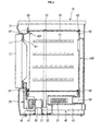
- a clothes drying machine comprises: a housing 10 forming an external appearance of the clothes drying machine; a drying tub 20 formed in the shape of a drum and rotatably mounted in the housing 10; a hot air introducing duct 30 to introduce hot air into the drying tub 20; and a hot air discharging duct 40 to discharge the hot air out of the drying tub 20.
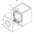
- a laundry-insertion hole 11 is formed at the front part of the housing 10 to allow the laundry to be inserted into and withdrawn from the drying tub therethrough.
- a hinged door 12 is attached to the front part of the housing 10 to close the laundry-insertion hole 11.
- a control panel 13 having control buttons 13a are disposed at the upper front part of the housing 10to control the operation of the clothes drying machine and a display unit 13b to display the operation of the clothes drying machine.
- the front part of the housing 10 is partly or wholly opened so that a repair of internal components of the clothes drying machine may be performed through the front of the housing 10 once the clothes drying machine is installed.
- an opening 10a is formed at the front part of the housing 10.
- the opening 10a is covered by means of a front cover 10F, which is detachably attached to the front part of the housing 10.
- the hot air introducing duct 30 includes a heater 31 mounted therein to heat air passing through the hot air introducing duct 30.
- One end of the hot air introducing duct 30 is open, and the other end of the hot air introducing duct 30 is connected to the drying tub 20 so that the hot air may be supplied to the drying tub 20.
- the hot air discharging duct 40 includes a blowing fan 41 mounted halfway therein to generate a suction force and a blowing force. The hot air is discharged out of the clothes drying machine via the hot air introducing duct 30, the drying tub 20, and the hot air discharging duct 40 by the blowing fan 41.
- the drying tub 20 is rotatably mounted in the housing 10.
- the drying tub 20 is rotated by a driving motor 50 mounted to the inner lower part of the housing 10 via a belt 53.
- the driving motor 50 drives the drying tub 20 and the blowing fan 41 at the same time.
- the driving motor 50 has a rotary shaft 51 directly connected to the blowing fan 41 at one end thereof so that the blowing fan 41 may be rotated.
- the other end of the rotary shaft 51 is connected to a pulley 52.
- the pulley 52 allows a rotating force to rotate the drying tub 20 to be transmitted to the drying tub 20 via the belt 53, which surrounds the drying tub 20.
- Reference numeral 21 indicates lifting blades 21 protruded inwardly from the inner surface of the drying tub 20 to lift the laundry.
- a front panel 60F is attached to the front of the drying tub 20to rotatably support the front end of the drying tub 20 while the front panel 60F covers the front part of the drying tub 20.
- a rear panel 60R is attached to the rear of the drying tub 20to rotatably support the rear end of the drying tub 20 while the rear panel 60R covers the rear part of the drying tub 20.
- the front panel 60F includes a ring-shaped supporting member 62 to rotatably support the inner circumference of the drying tub 20.
- the rear panel 60R includes another ring-shaped supporting member 62 to rotatably support the inner circumference of the drying tub 20.
- Friction pads 63 are respectively disposed at the outer circumferences of the front and rear panels 60F and 60R and are attached to supporting members 62. The friction pads 63 and the supporting members 62 cooperate to support the front and rear ends of the drying tub 20 at the front and rear panels 60F and 60R, respectively. Consequently, when the rotating force from the driving motor 50 is transmitted to the drying tub 20, the drying tub 20 is rotated while the front and rear ends of the drying tub 20 are slid along the friction pads 63 disposed at the front and rear panels 62, respectively.
- the hot air introducing duct 30 is provided at the rear panel 60R so as to introduce the hot air into the drying tub 20.
- the hot air discharging duct 40 is provided at the front panel 60F so as to discharge the hot air out of the drying tub 20. Consequently, the hot air is moved from the rear of the drying tub 20, where the hot air introducing duct 30 is mounted, to the front of the drying tub 20, where the hot air discharging duct 40 is mounted, so that the laundry in the drying tub 20 may be dried.
- the front panel 60F is provided with a through-hole 61, through which the laundry is inserted into and withdrawn from the drying tub.
- the through-hole 61 is formed at the inner side of the ring-shaped supporting member 62.
- a grill member 70 which is connected to the hot air discharging duct 40, is disposed below the front panel 60F.
- the grill member 70 is formed in the shape of a grid to prevent the laundry from being introduced into the hot air discharging duct 40 so that only the hot air is introduced into the hot air discharging duct 40.
- the hot air discharging duct 40 which is connected to the grill member 70, disposed at the inner lower front part of the housing 10, includes a side-extension duct part extending toward one side of the housing and a rear-extension duct part connected with the side-extension duct part and extending toward the rear of the housing so that the hot air, which is guided from the drying tub 20 via the grill member 70, is discharged out of the clothes drying machine.
- the hot air discharging duct 40 comprises: a fan casing 42 that is connected to the lower end of the grill member 70.
- the blowing fan 41 is mounted in the fan casing 42 and includes one end to extend toward one side of the housing so that the hot air is guided toward the side of the housing; and a discharging pipe 43 connected to the end of the fan casing 42 to extend toward the rear of the housing.
- the end of the fan casing 42 is bent so that the hot air may be guided toward the rear of the housing.
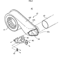
- the fan casing 42 includes a front case 42F, formed such that the front case 42F has a prescribed space, having an open rear part, and a rear case 42R to cover the open rear part of the front case 42F.
- a cleaning hole 44 is formed at the end of the front case 42F, which extends toward the side of the housing.
- a temperature sensor 46 is mounted to the hot air discharging duct 40 to detect the temperature of the hot air passing through the hot air discharging duct 40.
- the temperature sensor 46 is detachably fixed to the hot air discharging duct 40 by fixing members, such as screws.
- the temperature sensor 46 is disposed at the front part of the hot air discharging duct 40 so that repair or replacement of the temperature sensor 46 may be performed from the front of the hot air discharging duct 40.
- the opening 10 and the front cover 10F are provided at the front part of the housing 10, although, of course, other embodiments and arrangements are possible. Consequently, an operator may easily repair or replace the temperature sensor 46 mounted to the hot air discharging duct 40 in front of the hot air discharging duct 40 through the opening 10a once the front cover 10F is removed.
- an auxiliary temperature sensor 47 may be mounted to the hot air discharging duct 40 to intercept electric current that is supplied to the heater 31 when the temperature of the hot air exceeds a prescribed value.
- the auxiliary temperature sensor 47 is disposed at the front part of the hot air discharging duct 40 while being adjacent to the temperature sensor 46 and exposed toward the opening 10a in the same manner as the temperature sensor 46. Consequently, the auxiliary temperature sensor 47 may be easily repaired or replaced through the front of the housing 10 through the opening 10a.
- the interior of the hot air discharging duct 40 is cleaned through the cleaning hole 44, which is formed at the hot air discharging duct 40 such that the inside of the hot air discharging duct 40 communicates with the outside of the hot air discharging duct 40.
- the cleaning hole 44 is covered by a closing member 45, which is normally attached to the hot air discharging duct 40 so that the hot air may be moved through the hot air discharging duct 40.
- the closing member 45 may be removed from the hot air discharging duct 40 so that the interior of the hot air discharging duct 40 may be cleaned through the cleaning hole 44.
- the closing member 45 includes a curved inner surface, which corresponds to the bent part of the hot air discharging duct 40, so that the closing member 45 may cover the entirety of the bent part of the hot air discharging duct 40. Consequently, the flow direction of the hot air may be smoothly changed at the bent part of the hot air discharging duct 40.
- the temperature sensor 46 and the auxiliary temperature sensor 47 are detachably fixed to the closing member 45 by fixing members, such as screws. This is because the flow speed of the hot air is relatively decreased due to flow resistance when the flow direction of the hot air is changed at the bent part of the hot air discharging duct 40. Consequently, when the temperature sensor 46 and the auxiliary temperature sensor 47 are fixed to the closing member 45, which is disposed at the bent part of the hot air discharging duct 40, the period of time during which the hot air contacts the temperature sensor 46 and the auxiliary temperature sensor 47 is increased to accurately measure the temperature of the hot air. Also, the closing member 45 is easily removed from the hot air discharging duct 40 in a forward direction. Thus, the temperature sensor 46 and the auxiliary temperature sensor 47 may also be separated from the hot air discharging duct 40 and then removed from the housing 10 through the opening 10a. Consequently, the temperature sensor 46 and the auxiliary temperature sensor 47 may be easily repaired or replaced.
- the closing member 45 is made of a transparent material so that the closing member 45 serves as a transparent window.
- the closing member 45 may be separated from the hot air discharging duct 40 so that the cleaning hole 44 is opened. Consequently, the interior of the hot air discharging duct 40 may be easily cleaned through the cleaning hole 44.
- the clothes drying machine In order to prevent the hot air from leaking from between the closing member 45 and the hot air discharging duct 40, the clothes drying machine according to an embodiment of the present invention is provided with an engaging unit to engage the edge of the closing member 45 with the edge of the cleaning hole 44 of the hot air discharging duct 40.
- the engaging unit comprises engaging protrusions 42a and 45a and engaging grooves 45b and 42b, in which the engaging protrusions 42a and 45a are engaged, respectively.
- the engaging protrusions 42a and 45a and the engaging grooves 45b and 42b are provided at the edges of the cleaning hole 44 of the hot air discharging duct 40 and the closing member 45, respectively, such that the engaging protrusions 42a and 45a may be engaged in the corresponding engaging grooves 45b and 42b.
- the engaging protrusion 45a of the closing member 45 is engaged in the engaging groove 42b of the hot air discharging duct 40
- the engaging protrusion 42a of the hot air discharging duct 40 is engaged in the engaging groove 45b of the closing member 45.
- the engaging protrusions 42a and 45a are provided at the edge of the cleaning hole 44 of the hot air discharging duct 40 and the edge of the closing member 45 while extending along the cleaning hole 44 of the hot air discharging duct 40 and the edge of the closing member 45.
- the engaging grooves 42b and 45b are provided inside the engaging protrusions 42a and 45a, respectively, while extending in parallel with the engaging protrusions 42a and 45a. Consequently, the edge of the closing member 45 is entirely engaged with the edge of the cleaning hole 44 of the hot air discharging duct 40.
- Pluralities of supporting protrusions 45c, to protrude outwardly, are formed at the rear end of the closing member 45.
- a supporting groove 42c, in which the supporting protrusions 45c are formed and in which the supporting protrusions 45c are securely located, is formed at the front surface of the rear case 42Rso that the rear end of the closing member 45 may be supported by the rear case 42R.
- embodiments of the present invention provide a clothes drying machine having a temperature sensor mounted at the front part of a hot air discharging duct so that an operator has easy access to the temperature sensor. Consequently, repair or replacement of the temperature sensor may be easily and conveniently performed.
- a closing member to which the temperature sensor and an auxiliary temperature sensor of the clothes drying machine are fixed, is detachably attached to the hot air discharging duct such that the temperature sensor and the auxiliary temperature sensor may be withdrawn out of a housing of the clothes drying machine when the closing member is separated from the hot air discharging duct. Consequently, repair or replacement of the temperature sensor may be easily and conveniently performed.
- the closing member may be made of a transparent material such that the closing member serves as a transparent window. Consequently, contamination of the interior of the hot air discharging duct can be easily seen through the transparent closing member, whereby the interior of the hot air discharging duct is easily cleaned.
Landscapes
- Engineering & Computer Science (AREA)
- Textile Engineering (AREA)
- Control Of Washing Machine And Dryer (AREA)
- Detail Structures Of Washing Machines And Dryers (AREA)
Applications Claiming Priority (8)
| Application Number | Priority Date | Filing Date | Title |
|---|---|---|---|
| KR1020040027627A KR20050102329A (ko) | 2004-04-21 | 2004-04-21 | 의류건조기 |
| KR1020040027628A KR101095553B1 (ko) | 2004-04-21 | 2004-04-21 | 의류건조기 |
| KR2004027629 | 2004-04-21 | ||
| KR2004027628 | 2004-04-21 | ||
| KR1020040027624A KR101095550B1 (ko) | 2004-04-21 | 2004-04-21 | 의류건조기 |
| KR1020040027629A KR101022219B1 (ko) | 2004-04-21 | 2004-04-21 | 의류건조기 |
| KR2004027627 | 2004-04-21 | ||
| KR2004027624 | 2004-04-21 |
Publications (3)
| Publication Number | Publication Date |
|---|---|
| EP1589144A2 true EP1589144A2 (de) | 2005-10-26 |
| EP1589144A3 EP1589144A3 (de) | 2006-08-02 |
| EP1589144B1 EP1589144B1 (de) | 2009-04-15 |
Family
ID=34940392
Family Applications (1)
| Application Number | Title | Priority Date | Filing Date |
|---|---|---|---|
| EP05250385A Expired - Lifetime EP1589144B1 (de) | 2004-04-21 | 2005-01-26 | Wäschetrockner |
Country Status (3)
| Country | Link |
|---|---|
| US (1) | US7644516B2 (de) |
| EP (1) | EP1589144B1 (de) |
| DE (1) | DE602005013844D1 (de) |
Cited By (3)
| Publication number | Priority date | Publication date | Assignee | Title |
|---|---|---|---|---|
| EP2004899A4 (de) * | 2006-03-29 | 2011-06-29 | Daewoo Electronics Corp | Einsatzkupplungsventilatorgehäuse und damit ausgerüsteter trockner |
| DE102008051508B4 (de) * | 2007-10-15 | 2016-05-19 | Lg Electronics Inc. | Bekleidungstrockner |
| EP3124688A1 (de) * | 2015-07-27 | 2017-02-01 | Electrolux Appliances Aktiebolag | Ein wäschetrockner |
Families Citing this family (17)
| Publication number | Priority date | Publication date | Assignee | Title |
|---|---|---|---|---|
| US20020111680A1 (en) * | 2000-06-13 | 2002-08-15 | Michelson Gary K. | Ratcheted bone dowel |
| KR100556503B1 (ko) * | 2002-11-26 | 2006-03-03 | 엘지전자 주식회사 | 건조기의 건조 시간제어 방법 |
| US7627960B2 (en) * | 2003-06-30 | 2009-12-08 | General Electric Company | Clothes dryer drum projections |
| US20060063679A1 (en) * | 2004-09-17 | 2006-03-23 | Honeywell International Inc. | Semiconductor-insulator-semiconductor structure for high speed applications |
| CA2508860C (en) | 2005-05-30 | 2007-10-16 | Camco Inc. | Clothes dryer reversible door assembly |
| CA2508607C (en) * | 2005-05-30 | 2007-09-11 | Camco Inc. | Clothes dryer door assembly |
| EP1915480B1 (de) * | 2005-08-19 | 2018-03-28 | LG Electronics Inc. | Trocknungskanalanordnung und waschmaschine damit |
| KR100710395B1 (ko) * | 2006-01-25 | 2007-04-24 | 엘지전자 주식회사 | 의류 건조기 |
| EP1876280B1 (de) * | 2006-07-06 | 2010-09-22 | Candy S.p.A. | Trommel für eine Waschmaschine, einen Waschtrockner und dergleichen |
| KR101308510B1 (ko) * | 2007-11-05 | 2013-09-12 | 동부대우전자 주식회사 | 히터 내장형 흡기관을 구비하는 건조기 |
| KR101256145B1 (ko) * | 2007-11-05 | 2013-04-23 | 동부대우전자 주식회사 | 히터 내장형 흡기관을 구비하는 건조기 |
| KR20140106909A (ko) * | 2013-02-27 | 2014-09-04 | 엘지전자 주식회사 | 의류처리장치 |
| KR102047697B1 (ko) * | 2013-02-27 | 2019-11-22 | 엘지전자 주식회사 | 의류처리장치 |
| US9562314B2 (en) | 2013-02-27 | 2017-02-07 | Lg Electronics Inc. | Laundry treating apparatus |
| US9568244B2 (en) | 2013-02-27 | 2017-02-14 | Lg Electronics Inc. | Laundry treating apparatus |
| US9890496B2 (en) | 2014-09-30 | 2018-02-13 | Haier Us Appliance Solutions, Inc. | Impeller housing for an appliance |
| US9617678B2 (en) | 2014-10-24 | 2017-04-11 | Haier Us Appliance Solutions, Inc. | Impeller housing for an appliance |
Family Cites Families (18)
| Publication number | Priority date | Publication date | Assignee | Title |
|---|---|---|---|---|
| JPS517305A (en) * | 1974-07-05 | 1976-01-21 | Nissan Motor | Takitonainenkikanno shitsukakenshutsusochi |
| JPS6150599A (ja) * | 1984-08-18 | 1986-03-12 | 松下電器産業株式会社 | 乾燥機の制御装置 |
| US4840285A (en) * | 1986-10-02 | 1989-06-20 | Whirlpool Corporation | Cabinet construction for a dryer |
| JPH02307727A (ja) * | 1989-05-24 | 1990-12-20 | Hitachi Metals Ltd | 電気溶接される継手の溶接時間制御方法および継手 |
| US5042170A (en) * | 1990-09-04 | 1991-08-27 | Whirlpool Corporation | Lint collecting device |
| JP2819843B2 (ja) | 1991-02-25 | 1998-11-05 | 株式会社日立製作所 | 衣類乾燥機 |
| KR940006249B1 (ko) * | 1991-11-18 | 1994-07-13 | 주식회사 금성사 | 의류건조기의 건조시간 설정방법 |
| US5158446A (en) * | 1992-03-30 | 1992-10-27 | Rheem Manufacturing Company | Combination pressure and temperature limit control for a fuel-fired, forced draft heating appliance combustion product exhaust system |
| DE4447270A1 (de) * | 1994-12-30 | 1996-07-04 | Bosch Siemens Hausgeraete | Verfahren zum Steuern von Trockenvorgängen in Haushalt-Wäschetrocknern |
| US5555647A (en) * | 1995-08-23 | 1996-09-17 | White Consolidated Industries, Inc. | Motor mounted to blower housing |
| JPH0994397A (ja) * | 1995-09-29 | 1997-04-08 | Matsushita Electric Ind Co Ltd | 衣類乾燥機 |
| DE19704213C1 (de) * | 1997-02-05 | 1998-09-17 | Miele & Cie | System zur Erkennung unzulässiger Betriebszustände in einem Wäschetrockner |
| JP3544813B2 (ja) * | 1997-02-07 | 2004-07-21 | 株式会社東芝 | ドラム式洗濯機 |
| US5899055A (en) * | 1997-03-06 | 1999-05-04 | Rowse Hydraulic Rakes Co., Inc. | Pull type rake |
| US5899005A (en) | 1997-03-13 | 1999-05-04 | General Electric Company | System and method for predicting the dryness of clothing articles |
| DE19755916A1 (de) | 1997-12-10 | 1999-06-17 | Aeg Hausgeraete Gmbh | Wäschetrockner |
| KR20020062446A (ko) | 2001-01-20 | 2002-07-26 | 엘지전자주식회사 | 배기식 건조기의 건조도 감지 장치 및 이를 이용한 제어방법 |
| GB2390667B (en) * | 2002-07-10 | 2005-10-26 | Gen Domestic Appliances Ltd | Tumble dryers |
-
2005
- 2005-01-26 EP EP05250385A patent/EP1589144B1/de not_active Expired - Lifetime
- 2005-01-26 DE DE602005013844T patent/DE602005013844D1/de not_active Expired - Lifetime
- 2005-03-11 US US11/077,155 patent/US7644516B2/en not_active Expired - Fee Related
Cited By (3)
| Publication number | Priority date | Publication date | Assignee | Title |
|---|---|---|---|---|
| EP2004899A4 (de) * | 2006-03-29 | 2011-06-29 | Daewoo Electronics Corp | Einsatzkupplungsventilatorgehäuse und damit ausgerüsteter trockner |
| DE102008051508B4 (de) * | 2007-10-15 | 2016-05-19 | Lg Electronics Inc. | Bekleidungstrockner |
| EP3124688A1 (de) * | 2015-07-27 | 2017-02-01 | Electrolux Appliances Aktiebolag | Ein wäschetrockner |
Also Published As
| Publication number | Publication date |
|---|---|
| EP1589144A3 (de) | 2006-08-02 |
| US7644516B2 (en) | 2010-01-12 |
| DE602005013844D1 (de) | 2009-05-28 |
| US20050235519A1 (en) | 2005-10-27 |
| EP1589144B1 (de) | 2009-04-15 |
Similar Documents
| Publication | Publication Date | Title |
|---|---|---|
| EP1589144A2 (de) | Wäschetrockner | |
| US8266816B2 (en) | Clothes dryer and door thereof | |
| US20120144687A1 (en) | Clothing dryer | |
| EP1672114B1 (de) | Wäschetrockner | |
| US20070227031A1 (en) | Insertion coupling type fan housing and dryer having the same | |
| US20060085996A1 (en) | Clothing dryer | |
| CA2629493A1 (en) | Clothes dryer with louvre cover | |
| EP1584732B1 (de) | Wäschetrockner | |
| CA2531591C (en) | Clothes dryer with improved air flow | |
| CN100500977C (zh) | 衣物烘干机 | |
| US20070089316A1 (en) | Clothing drying machine | |
| US20070006485A1 (en) | Clothes drying machine | |
| KR100599038B1 (ko) | 의류건조기 | |
| KR100599041B1 (ko) | 의류건조기 | |
| CA2506502C (en) | Laundry dryer with novel exhaust pipe installation structure | |
| KR101095553B1 (ko) | 의류건조기 | |
| KR100589907B1 (ko) | 의류건조기 | |
| KR100452367B1 (ko) | 건조기 | |
| US20250207316A1 (en) | Clothes dryer | |
| KR100637661B1 (ko) | 의류건조기 | |
| KR20050102329A (ko) | 의류건조기 | |
| JPH0725193Y2 (ja) | コイン式衣類乾燥機 | |
| KR100608133B1 (ko) | 의류건조기 | |
| EP1607513A1 (de) | Wäschetrockner | |
| KR20050102331A (ko) | 의류건조기 |
Legal Events
| Date | Code | Title | Description |
|---|---|---|---|
| PUAI | Public reference made under article 153(3) epc to a published international application that has entered the european phase |
Free format text: ORIGINAL CODE: 0009012 |
|
| AK | Designated contracting states |
Kind code of ref document: A2 Designated state(s): AT BE BG CH CY CZ DE DK EE ES FI FR GB GR HU IE IS IT LI LT LU MC NL PL PT RO SE SI SK TR |
|
| AX | Request for extension of the european patent |
Extension state: AL BA HR LV MK YU |
|
| PUAL | Search report despatched |
Free format text: ORIGINAL CODE: 0009013 |
|
| AK | Designated contracting states |
Kind code of ref document: A3 Designated state(s): AT BE BG CH CY CZ DE DK EE ES FI FR GB GR HU IE IS IT LI LT LU MC NL PL PT RO SE SI SK TR |
|
| AX | Request for extension of the european patent |
Extension state: AL BA HR LV MK YU |
|
| 17P | Request for examination filed |
Effective date: 20070112 |
|
| AKX | Designation fees paid |
Designated state(s): DE FR GB IT |
|
| 17Q | First examination report despatched |
Effective date: 20070507 |
|
| GRAP | Despatch of communication of intention to grant a patent |
Free format text: ORIGINAL CODE: EPIDOSNIGR1 |
|
| GRAP | Despatch of communication of intention to grant a patent |
Free format text: ORIGINAL CODE: EPIDOSNIGR1 |
|
| GRAS | Grant fee paid |
Free format text: ORIGINAL CODE: EPIDOSNIGR3 |
|
| GRAA | (expected) grant |
Free format text: ORIGINAL CODE: 0009210 |
|
| AK | Designated contracting states |
Kind code of ref document: B1 Designated state(s): DE FR GB IT |
|
| REG | Reference to a national code |
Ref country code: GB Ref legal event code: FG4D |
|
| REF | Corresponds to: |
Ref document number: 602005013844 Country of ref document: DE Date of ref document: 20090528 Kind code of ref document: P |
|
| PLBE | No opposition filed within time limit |
Free format text: ORIGINAL CODE: 0009261 |
|
| STAA | Information on the status of an ep patent application or granted ep patent |
Free format text: STATUS: NO OPPOSITION FILED WITHIN TIME LIMIT |
|
| 26N | No opposition filed |
Effective date: 20100118 |
|
| PGFP | Annual fee paid to national office [announced via postgrant information from national office to epo] |
Ref country code: DE Payment date: 20140113 Year of fee payment: 10 |
|
| PGFP | Annual fee paid to national office [announced via postgrant information from national office to epo] |
Ref country code: FR Payment date: 20140113 Year of fee payment: 10 Ref country code: IT Payment date: 20140113 Year of fee payment: 10 |
|
| PGFP | Annual fee paid to national office [announced via postgrant information from national office to epo] |
Ref country code: GB Payment date: 20140117 Year of fee payment: 10 |
|
| REG | Reference to a national code |
Ref country code: DE Ref legal event code: R119 Ref document number: 602005013844 Country of ref document: DE |
|
| GBPC | Gb: european patent ceased through non-payment of renewal fee |
Effective date: 20150126 |
|
| PG25 | Lapsed in a contracting state [announced via postgrant information from national office to epo] |
Ref country code: GB Free format text: LAPSE BECAUSE OF NON-PAYMENT OF DUE FEES Effective date: 20150126 Ref country code: DE Free format text: LAPSE BECAUSE OF NON-PAYMENT OF DUE FEES Effective date: 20150801 |
|
| REG | Reference to a national code |
Ref country code: FR Ref legal event code: ST Effective date: 20150930 |
|
| PG25 | Lapsed in a contracting state [announced via postgrant information from national office to epo] |
Ref country code: FR Free format text: LAPSE BECAUSE OF NON-PAYMENT OF DUE FEES Effective date: 20150202 |
|
| PG25 | Lapsed in a contracting state [announced via postgrant information from national office to epo] |
Ref country code: IT Free format text: LAPSE BECAUSE OF NON-PAYMENT OF DUE FEES Effective date: 20150126 |