EP1589246B1 - Butée de débrayage pour un embrayage à friction - Google Patents
Butée de débrayage pour un embrayage à friction Download PDFInfo
- Publication number
- EP1589246B1 EP1589246B1 EP04009754A EP04009754A EP1589246B1 EP 1589246 B1 EP1589246 B1 EP 1589246B1 EP 04009754 A EP04009754 A EP 04009754A EP 04009754 A EP04009754 A EP 04009754A EP 1589246 B1 EP1589246 B1 EP 1589246B1
- Authority
- EP
- European Patent Office
- Prior art keywords
- release bearing
- coupling element
- bearing according
- diaphragm spring
- ring
- Prior art date
- Legal status (The legal status is an assumption and is not a legal conclusion. Google has not performed a legal analysis and makes no representation as to the accuracy of the status listed.)
- Expired - Lifetime
Links
- 230000008878 coupling Effects 0.000 claims description 62
- 238000010168 coupling process Methods 0.000 claims description 62
- 238000005859 coupling reaction Methods 0.000 claims description 62
- 210000002105 tongue Anatomy 0.000 claims description 44
- 238000005096 rolling process Methods 0.000 claims description 14
- 239000011324 bead Substances 0.000 claims description 4
- 229910000639 Spring steel Inorganic materials 0.000 claims description 2
- 230000005540 biological transmission Effects 0.000 description 3
- 238000000034 method Methods 0.000 description 2
- 244000089486 Phragmites australis subsp australis Species 0.000 description 1
- 230000006978 adaptation Effects 0.000 description 1
- 238000000137 annealing Methods 0.000 description 1
- 230000000994 depressogenic effect Effects 0.000 description 1
- 238000006073 displacement reaction Methods 0.000 description 1
- 230000007935 neutral effect Effects 0.000 description 1
- 230000007704 transition Effects 0.000 description 1
Images


Classifications
-
- F—MECHANICAL ENGINEERING; LIGHTING; HEATING; WEAPONS; BLASTING
- F16—ENGINEERING ELEMENTS AND UNITS; GENERAL MEASURES FOR PRODUCING AND MAINTAINING EFFECTIVE FUNCTIONING OF MACHINES OR INSTALLATIONS; THERMAL INSULATION IN GENERAL
- F16D—COUPLINGS FOR TRANSMITTING ROTATION; CLUTCHES; BRAKES
- F16D23/00—Details of mechanically-actuated clutches not specific for one distinct type
- F16D23/12—Mechanical clutch-actuating mechanisms arranged outside the clutch as such
- F16D23/14—Clutch-actuating sleeves or bearings; Actuating members directly connected to clutch-actuating sleeves or bearings
- F16D23/143—Arrangements or details for the connection between the release bearing and the diaphragm
- F16D23/144—With a disengaging thrust-ring distinct from the release bearing, and secured to the diaphragm
Definitions
- the invention relates to a releaser for a friction clutch of a motor vehicle.
- Such a release (see eg US 4,159,052 . GB 814,693 . DE 10 114 844 and US 2002/134 640 ) is used to actuate a vehicle clutch equipped with a diaphragm spring as Ausgurorgan, wherein the radially inwardly directed free ends of the diaphragm spring are in abutting contact with a rolling bearing arranged on a sliding sleeve.
- the invention has as its object to provide a releaser, in which a friction occurring between a release bearing and a diaphragm spring is further reduced. Furthermore, a coupling element arranged between a release bearing and a clutch diaphragm spring is to be improved.
- the inventor has recognized that the friction losses in the region of the diaphragm spring tongue ends can be significantly reduced if the coupling element arranged on the release bearing and the spring tongue ends cooperating therewith can execute a similar movement.
- the invention is based on the further finding that an approximately circular path-shaped pivoting movement of the diaphragm spring tongues can be simulated by an axial movement of the releaser and an additional, radially executed movement of the coupling element.
- the diaphragm spring tongue ends can be supported on an axial movement of the release bearing on the receiving portion, and force the receiving portion in the radial direction on the Verschwenkbahn.
- the coupling element is designed to be relatively stiff in the axial direction, whereby the axial movement of the release bearing can be transmitted substantially lossless on the diaphragm spring tongue ends.
- a restoring force acting on the disengaging device on the receiving portion causes the receiving portion to abut against the diaphragm spring tongues in a free manner both in each phase of engagement and disengagement of the friction clutch, thus ensuring an immediate force transmission.
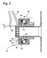
- Fig. 1 shows an overview of a release 10 with a guide tube 14 arranged around a sliding sleeve 16 which carries at one end of a bearing designed as a rolling bearing 18 which is in abutting contact with spring tongues 26 of a diaphragm spring 24 for actuating a friction clutch 12.
- the roller bearing 18 includes an outer, first bearing ring 20 which radially slidably bears against a ring flange 17 for self-adjustment of the release bearing, an inner, second bearing ring 22 and on raceways of the bearing rings 20, 22 guided rolling elements (balls) 21.
- the diaphragm spring 24 provides the Release member of the friction clutch 12, which acts with its radially outer region on a pressure plate 25 and exerts a force on a clutch disc not shown in the drawing and a likewise not shown flywheel in the engaged state.
- the diaphragm spring 24 is mounted in the circumferential direction at a plurality of positions on a coupling housing 27 about which the spring tongues 26 can pivot with their free ends 28 within the plane of the drawing radially to an axis A of the release device during disengagement to a limited extent.
- the operative connection between the rolling bearing 18 and the spring tongues 26 is produced by a coupling element 30 arranged on the inner ring 22 of the roller bearing 18. This points as in Fig.
- a counter to a restoring force elastically displaceable receiving portion in the form of a pivot arm 32 which has the free end 28 of a diaphragm spring tongue 26 with a arranged on this and radially extending abutment portion 50 and an axial extending abutment portion 52 ( Fig. 3 ) receives and supports.
- a snap contour 54 in the form of a radially outwardly directed radial bead is also formed on the pivot arm 32, in which the diaphragm spring tongues 26 can snap.
- the pivot arm 32 extends substantially in the axial direction and merges into a radially directed center region 46, which is adjoined by a pipe extension 38 extending in parallel at least in sections to the pivot arm 32, which in turn forms a region forming a disk 36 radially outward empties.
- a pipe extension 38 extending in parallel at least in sections to the pivot arm 32, which in turn forms a region forming a disk 36 radially outward empties.
- the disc 36 and the axially extending pipe extension 38 a holding portion 34, with which the coupling element 30 is arranged on a correspondingly formed extension 40 on the rotating bearing ring 22.
- connection of the coupling element 30 to the encircling bearing ring 22 may be radially in play, in order to allow a self-adjustment of the spring tongues in case of an offset of the axis of rotation of the coupling to the axis A.
- the coupling element 30 forms, with the sections 38, 32 adjoining the center region 46 on both sides, a U-shaped loop which is arranged substantially in an annular space 37 formed radially between the guide tube 14 and the roller bearing 18.
- the coupling element 30 is designed for play and loss-free transmission of an axial disengagement movement of the releaser 10 substantially axially very stiff, whereas the standing in operative connection with the diaphragm spring tongue ends 28 pivot arm 32 permits radial movement.
- the coupling element 30 preferably has a number of receiving sections 32 corresponding to the diaphragm spring tongues 26.
- the diaphragm spring tongue ends 28 can be made as sharp-edged and acute-angled as possible and can be received by a preferably sharp-edged receiving portion 32 of the coupling element 30 as well.
- the pivoting center 48 is in the embodiment of Figures 1 - 3 arranged on the roller bearing 18 facing axial side of the diaphragm spring 24, which at the same time assumes a relation to the spring tongue ends 28 further outward radial position.
- the radialorientsungskomonente the pivot arm 32 is in this case additionally superposed with an axial movement component directed towards the roller bearing 18, which, however, is comparatively small in relation to the axial input movement of the releaser 10.
- the coupling element 30 is pressed by means of a press fit with the pipe socket 38 in the bearing inner ring 22.
- the coupling element 30 can also be secured axially in the bearing ring 22, in that the tubular projection 38 forms a radial bead 42, which engages in a groove 44 formed on the circumferential ring 22.
- An even better axial support of the coupling element 30 can be achieved by a direct contact contact of the radially extending central region 46 on the release bearing 18.
- the inner ring 22 of the bearing 18 is provided for this purpose with an inwardly directed radial collar 56, which in addition to a further radially outwardly disposed radial collar 57 can receive and transmit axial forces.
- the pivoting center 48 is arranged in this embodiment, approximately at the transition of the central region 46 in the pivot arm 32 and is located on a substantially same radial position as the spring tongue ends 28, whereby the pivot arm 32 are moved only slightly on pivoting axially, but mainly radially inward can.
- Verschwenk scholar 48 may be disposed radially inwardly with respect to the diaphragm spring tongue ends 28, resulting in that in addition to the axial movement carried out by the release bearing 18 is added to the axial component occurring during the pivoting of the pivoting arm 32.
- Such a design results in a shortened actuating travel to a slightly increased operating force during the disengagement process.
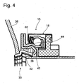
- Fig. 6 can the arrangement according to Fig. 5 be further simplified by the coupling element 30a is performed in one piece with the encircling bearing ring.
- coupling element 30b is designed substantially tubular and engages with its one axial end portion, which a holding portion 34 forms, in a radial collar 56 formed by the inner ring 22, which transmits the rotational and disengaging movement of the coupling element 30 b.
- a variant of a releaser 10 is shown, in which the coupling element 30c is held axially between the diaphragm spring tongue ends 28 and the rotating roller bearing inner ring 22 by the bias of the diaphragm spring 24 to a radial collar 57 of the release bearing 18.
- the diaphragm spring tongues 26 are executed radially shortened compared to the above-described embodiments and engage radially outside of the rolling bearing 18 on the pivoting arms 32 of the coupling element 30c.
- Such an arrangement may be useful in the applications where due to a given space, the roller bearing 18 should be located as close to the axis A of the release device.
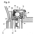
- a coupling element 30d with a release device with a device for compensating wobbling movements.
- This device has a Kunststoffeinstellring 58 working as a sliding element with a convexly oriented in the direction of the rolling bearing 18 surface portion 62, which is in contact with a formed on the inner ring 22 concave surface portion 60 with an identical ball radius.
- the adjusting ring 58 engages by means of latching hooks 64 on the inner ring 22 radially inwardly directed annular web 66, whereby a total of a captive, but pivoting arrangement is created.
- the coupling element 30d is rotatably connected to the adjusting ring 58 by these, for example, also by a positive connection, For example, in the form of a snap connection, or wherein the Kunststoffeinstellring 58 is molded onto the coupling element 30d.
- the coupling element 30d at the same time form a stiffening or a basic structure for the adjustment ring 58, which then needs to be performed less massive.
- the coupling element 30e as a double-walled, unilaterally closed by the middle portion 46 tube profile with a radially inner tube section 71, which forms the holding portion, and designed with a radially outer, segmented in the circumferential direction while pivot arms 32 having pipe section 72.
- the inner tube section 34 is supported radially with an annular abutment section 70, displaceable for adjustment purposes, at the end region of an axial projection 68 of the inner ring 22, whereby the coupling element 30e is held self-centering on the release bearing 18.
- the coupling element 30e extends substantially on the axial side of the diaphragm spring 24 facing the coupling 12, the diaphragm spring tongue ends 28 being engaged behind by a radially outwardly directed collar 74 and thus being able to be pivoted in the direction of the clutch 12 during a disengaging operation.
- the inner pipe section 71 is axially extremely stiff, whereas the axial stiffness plays a minor role in the design of the pivot arms 32 as a result of the direction reversal of the force acting on the spring tongue ends 28 acting opposite to the previously described embodiments. This allows the pivot arms 32 are optimized with respect to their radial elastic displacement. This variant is compared with the known from the prior art embodiments about space neutral, since for the arrangement of the coupling element 30e a previously unused space is claimed.
- a holding plate 76 is provided, which snaps with a pipe section 77 in the groove 44 on the inner ring 22 and with an outwardly directed annular collar 78 holds the abutment portion 70 of the coupling element 30f on the axial projection 68.
- coupling element can be advantageously produced by conventional forming and annealing techniques of spring steel.
- the coupling element engagement means for example radial webs, which engage in the intermediate space formed by the diaphragm spring tongues for rotational driving.
- a coupling element can optionally be pre-assembled either on the release button or on the diaphragm spring, and thus be assigned to the scope of delivery of the release device or the clutch.
Landscapes
- Engineering & Computer Science (AREA)
- General Engineering & Computer Science (AREA)
- Mechanical Engineering (AREA)
- Mechanical Operated Clutches (AREA)
Claims (19)
- Butée de débrayage (10) pour un embrayage à friction (12) d'un véhicule automobile, comprenant:- un tube de guidage (14),- un manchon coulissant (16) déplaçable axialement sur le tube de guidage (14),- un palier de débrayage (18) disposé coaxialement sur le manchon coulissant (16), avec une première bague de palier (20) disposée de manière solidaire en rotation par rapport au manchon coulissant (16), des corps de roulement (21) et une deuxième bague de palier périphérique (22),- un élément d'accouplement (30, 30a-f), qui est disposé en liaison fonctionnelle entre la bague de palier périphérique (22) et une extrémité libre (28) de langues de ressort (26) d'un ressort à membrane (24) servant d'organe d'actionnement de l'embrayage à friction (12),caractérisée en ce que
l'élément d'accouplement (30, 30a-f) présente une portion de réception (32) pouvant être décalée dans la direction radiale à l'encontre d'une force de rappel, réalisée sous forme de bras pivotant élastique, qui comprend une portion d'appui radiale (50) et une portion d'appui axiale (52) s'y raccordant, sur lesquelles s'appliquent les extrémités des langues de ressort à membrane (28) à la fois radialement et axialement, l'élément d'accouplement (30, 30a-f) étant disposé avec une portion de retenue (34) vers la bague de palier périphérique (22), de sorte que dans le cas d'un actionnement axial de la butée de débrayage (10), un décalage radial des extrémités des langues de ressort à membrane (28) peut être reçu sensiblement sans frottement par l'élément d'accouplement (30, 30a-f). - Butée de débrayage selon la revendication 1, caractérisée en ce que
le nombre des portions de réception (32) de l'élément d'accouplement (30, 30a-f) correspond au nombre des langues de ressort à membrane (26). - Butée de débrayage selon la revendication 2, caractérisée en ce que
le bras pivotant (32) est disposé au moins en partie dans un espace annulaire (37) réalisé radialement entre le tube de guidage (14) et le palier à roulement (18). - Butée de débrayage selon la revendication 2 ou 3, caractérisée en ce que
le bras pivotant (32) est disposé radialement en dehors du palier à roulement (18). - Butée de débrayage selon l'une quelconque des revendications précédentes,
caractérisée en ce que
la portion de retenue (34) comprend un disque (36) s'étendant radialement et un insert tubulaire (38) s'étendant axialement, avec lesquels l'élément d'accouplement (30) est disposé contre une saillie (40) réalisée de manière correspondante sur la bague de palier périphérique (22). - Butée de débrayage selon la revendication 5, caractérisée en ce que
l'insert tubulaire (38) présente un bourrelet radial (42), qui vient en prise dans une goulotte (44) formée sur la bague périphérique (22). - Butée de débrayage selon l'une quelconque des revendications précédentes,
caractérisée en ce que
le bras pivotant (32) est réalisé essentiellement axialement et se raccorde par le biais d'une région centrale (46) à l'insert tubulaire (38) de la portion de retenue (34). - Butée de débrayage selon l'une quelconque des revendications précédentes,
caractérisée en ce que
le bras pivotant (32) peut effectuer un mouvement de pivotement approximativement circulaire autour d'un centre de pivotement (48) imaginaire dans la région centrale (46) ou dans la portion de retenue (34). - Butée de débrayage selon la revendication 8, caractérisée en ce que
le centre de pivotement (48) est disposé du côté axial du ressort à membrane (24) tourné vers le palier à roulement (18). - Butée de débrayage selon la revendication 8, caractérisée en ce que
le centre de pivotement (48) est disposé du côté axial du ressort à membrane (24) tourné vers l'embrayage (12). - Butée de débrayage selon l'une quelconque des revendications 8 à 10,
caractérisée en ce que
le centre de pivotement (48) est disposé sur une position radiale essentiellement identique aux extrémités des langues de ressort (28). - Butée de débrayage selon l'une quelconque des revendications précédentes,
caractérisée en ce que
le bras pivotant (32) présente un contour encliquetable (54) pour recevoir une extrémité des langues de ressort à membrane (28). - Butée de débrayage selon l'une quelconque des revendications 7 à 12,
caractérisée en ce que
la région centrale (46) de l'élément d'accouplement (30) s'appuie sur la butée de débrayage. - Butée de débrayage selon l'une quelconque des revendications précédentes,
caractérisée en ce que
la bague de palier périphérique (22) est réalisée d'une seule pièce avec l'élément d'accouplement (30). - Butée de débrayage selon l'une quelconque des revendications précédentes,
caractérisée en ce que
l'élément d'accouplement (30b) est essentiellement tubulaire. - Butée de débrayage selon l'une quelconque des revendications précédentes,
caractérisée en ce que
l'élément d'accouplement (30, 30a-f) présente des moyens d'engagement qui viennent en prise pour l'entraînement en rotation conjoint dans les espaces intermédiaires formés par les langues de ressort à membrane (26). - Butée de débrayage selon l'une quelconque des revendications précédentes,
dans laquelle la butée de débrayage (10) présente un dispositif pour compenser les mouvements de nutation avec une bague d'ajustement (58), qui présente avec la bague de palier périphérique (22) une région de contact commune (60, 62) pour un pivotement mutuel limité,
caractérisée en ce que
l'élément d'accouplement (30d) est disposé sur la bague d'ajustement (58). - Butée de débrayage selon la revendication 19, caractérisée en ce que
la bague d'ajustement (58) est disposée avec jeu et de manière imperdable sur la bague de palier périphérique (22). - Butée de débrayage selon l'une quelconque des revendications précédentes,
caractérisée en ce que
l'élément d'accouplement (30, 30a-f) est formé en acier à ressort.
Priority Applications (4)
| Application Number | Priority Date | Filing Date | Title |
|---|---|---|---|
| EP04009754A EP1589246B1 (fr) | 2004-04-24 | 2004-04-24 | Butée de débrayage pour un embrayage à friction |
| DE502004011509T DE502004011509D1 (de) | 2004-04-24 | 2004-04-24 | Ausrücker für eine Reibungskupplung |
| BR0500625-2A BRPI0500625A (pt) | 2004-04-24 | 2005-02-28 | Dispositivo de desengate para uma embreagem de fricção |
| US11/112,452 US7264103B2 (en) | 2004-04-24 | 2005-04-22 | Release device for a friction clutch |
Applications Claiming Priority (1)
| Application Number | Priority Date | Filing Date | Title |
|---|---|---|---|
| EP04009754A EP1589246B1 (fr) | 2004-04-24 | 2004-04-24 | Butée de débrayage pour un embrayage à friction |
Publications (2)
| Publication Number | Publication Date |
|---|---|
| EP1589246A1 EP1589246A1 (fr) | 2005-10-26 |
| EP1589246B1 true EP1589246B1 (fr) | 2010-08-11 |
Family
ID=34924723
Family Applications (1)
| Application Number | Title | Priority Date | Filing Date |
|---|---|---|---|
| EP04009754A Expired - Lifetime EP1589246B1 (fr) | 2004-04-24 | 2004-04-24 | Butée de débrayage pour un embrayage à friction |
Country Status (4)
| Country | Link |
|---|---|
| US (1) | US7264103B2 (fr) |
| EP (1) | EP1589246B1 (fr) |
| BR (1) | BRPI0500625A (fr) |
| DE (1) | DE502004011509D1 (fr) |
Families Citing this family (7)
| Publication number | Priority date | Publication date | Assignee | Title |
|---|---|---|---|---|
| DE102006034011A1 (de) * | 2006-07-22 | 2008-01-24 | Schaeffler Kg | Halterung, insbesondere für ein Kupplungsausrücklager |
| EP2146108A1 (fr) | 2008-07-16 | 2010-01-20 | ZF Friedrichshafen AG | Dispositif de débrayage doté d'un élément d'embrayage destiné à l'actionnement d'un embrayage à friction d'un véhicule automobile |
| FR2961280B1 (fr) * | 2010-06-09 | 2014-01-10 | Skf Ab | Dispositif de butee de debrayage comprenant une bague d'usure. |
| US8607955B2 (en) * | 2011-12-05 | 2013-12-17 | Advanced Clutch Technology, Inc. | Release for pull type clutch mechanism |
| DE102012206718A1 (de) * | 2012-04-24 | 2013-10-24 | Zf Friedrichshafen Ag | Anlaufteller für eine Reibungskupplung |
| FR3034830B1 (fr) | 2015-04-07 | 2018-10-12 | Aktiebolaget Skf | Butee d'embrayage-debrayage et vehicule automobile equipe d'une telle butee |
| CN107152468A (zh) * | 2017-06-12 | 2017-09-12 | 中国航发哈尔滨东安发动机有限公司 | 一种带过载保护的摩擦式离合器 |
Family Cites Families (10)
| Publication number | Priority date | Publication date | Assignee | Title |
|---|---|---|---|---|
| US2445638A (en) * | 1944-11-03 | 1948-07-20 | Saks Ira | Friction clutch |
| GB814693A (en) * | 1956-05-09 | 1959-06-10 | Kurt Haussermann | Pressure body for resilient members in particular for plate spring-like friction clutches for motor vehicles and the like |
| SE340728B (fr) * | 1967-03-03 | 1971-11-29 | Fichtel & Sachs Ag | |
| DE2327022C3 (de) * | 1973-05-26 | 1978-10-12 | Skf Kugellagerfabriken Gmbh, 8720 Schweinfurt | Reibungskupplung, insbesondere für Kraftfahrzeuge |
| DE2327937C3 (de) * | 1973-06-01 | 1978-09-28 | Skf Kugellagerfabriken Gmbh, 8720 Schweinfurt | Befestigung eines Ausrucklagers in einer Reibungskupplung fur Kraftfahrzeuge |
| DE7621572U1 (de) * | 1976-07-08 | 1976-10-28 | Skf Kugellagerfabriken Gmbh, 8720 Schweinfurt | Kupplungsausruecker, insbesondere fuer kraftfahrzeuge |
| DE3414836A1 (de) * | 1984-04-19 | 1985-10-24 | Fichtel & Sachs Ag, 8720 Schweinfurt | Reibungskupplung mit loesbarer schnappverbindung |
| DE10114844B4 (de) * | 2001-03-24 | 2013-02-28 | Schaeffler Technologies AG & Co. KG | Selbsteinstellendes Kupplungsausrücklager |
| DE10114845B4 (de) * | 2001-03-24 | 2012-05-31 | Schaeffler Technologies Gmbh & Co. Kg | Selbsteinstellendes Kupplungsausrücklager |
| DE10136424C1 (de) * | 2001-07-26 | 2002-10-10 | Zf Sachs Ag | Ausrücker für eine Reibungskupplung |
-
2004
- 2004-04-24 EP EP04009754A patent/EP1589246B1/fr not_active Expired - Lifetime
- 2004-04-24 DE DE502004011509T patent/DE502004011509D1/de not_active Expired - Lifetime
-
2005
- 2005-02-28 BR BR0500625-2A patent/BRPI0500625A/pt not_active IP Right Cessation
- 2005-04-22 US US11/112,452 patent/US7264103B2/en not_active Expired - Fee Related
Also Published As
| Publication number | Publication date |
|---|---|
| BRPI0500625A (pt) | 2005-12-06 |
| US20050236250A1 (en) | 2005-10-27 |
| DE502004011509D1 (de) | 2010-09-23 |
| US7264103B2 (en) | 2007-09-04 |
| EP1589246A1 (fr) | 2005-10-26 |
Similar Documents
| Publication | Publication Date | Title |
|---|---|---|
| EP2201258B2 (fr) | Système d'actionnement d'embrayage | |
| EP2326853B1 (fr) | Dispositif d'actionnement pour double embrayage | |
| EP2739873B1 (fr) | Système de débrayage | |
| DE3013298A1 (de) | Reibungskupplungseinheit | |
| DE10064459A1 (de) | Doppelkupplung, insbesondere für Kraftfahrzeuge | |
| EP3030802B1 (fr) | Embrayage à friction équipée d'un moyen d'actionnement | |
| EP1589246B1 (fr) | Butée de débrayage pour un embrayage à friction | |
| EP2554868B1 (fr) | dispositif de débrayage | |
| DE4230324C2 (de) | Kupplungsbetätigungseinrichtung | |
| DE102012001836B4 (de) | Schalttransmitter eines sperrsynchronisierten Schaltgetriebes | |
| WO2012072394A1 (fr) | Actionneur | |
| DE19952124B4 (de) | Kupplungsausrückhebel mit Rollen | |
| DE102015100906B4 (de) | Synchronisiereinrichtung, Kupplungsanordnung und Antriebsanordnung | |
| DE102012102577A1 (de) | Verschleißnachstellvorrichtung einer Scheibenbremse und entsprechende Scheibenbremse | |
| EP2529127A1 (fr) | Dispositif de désaccouplement pour des embrayages de véhicules | |
| DE112008001323B4 (de) | Kupplungseinrichtung mit einer Membran, die ständig eine axiale Vorspannkraft auf ein Lager einer Gegendruckplatte ausübt | |
| EP3682132A1 (fr) | Embrayage à roue libre présentant une force de réglage induite par frottement | |
| DE19840259C2 (de) | Druckanordnung für eine Kupplung | |
| DE102015220266A1 (de) | Ausrücklager | |
| DE10136424C1 (de) | Ausrücker für eine Reibungskupplung | |
| WO2023186211A1 (fr) | Dispositif de roue libre et ensemble embrayage comprenant le dispositif de roue libre | |
| EP1229263B1 (fr) | Dispositif de synchronisation | |
| DE10023983A1 (de) | Hydrodynamische Kopplungseinrichtung | |
| DE102011102326A1 (de) | Selbstnachstellende Doppelkupplung | |
| WO2011018436A1 (fr) | Accouplement à griffes avec des flancs à griffes inclinés dans le sens axial |
Legal Events
| Date | Code | Title | Description |
|---|---|---|---|
| PUAI | Public reference made under article 153(3) epc to a published international application that has entered the european phase |
Free format text: ORIGINAL CODE: 0009012 |
|
| 17P | Request for examination filed |
Effective date: 20050114 |
|
| AK | Designated contracting states |
Kind code of ref document: A1 Designated state(s): AT BE BG CH CY CZ DE DK EE ES FI FR GB GR HU IE IT LI LU MC NL PL PT RO SE SI SK TR |
|
| AX | Request for extension of the european patent |
Extension state: AL HR LT LV MK |
|
| AKX | Designation fees paid |
Designated state(s): DE FR |
|
| GRAP | Despatch of communication of intention to grant a patent |
Free format text: ORIGINAL CODE: EPIDOSNIGR1 |
|
| GRAS | Grant fee paid |
Free format text: ORIGINAL CODE: EPIDOSNIGR3 |
|
| GRAA | (expected) grant |
Free format text: ORIGINAL CODE: 0009210 |
|
| AK | Designated contracting states |
Kind code of ref document: B1 Designated state(s): DE FR |
|
| REF | Corresponds to: |
Ref document number: 502004011509 Country of ref document: DE Date of ref document: 20100923 Kind code of ref document: P |
|
| PLBE | No opposition filed within time limit |
Free format text: ORIGINAL CODE: 0009261 |
|
| STAA | Information on the status of an ep patent application or granted ep patent |
Free format text: STATUS: NO OPPOSITION FILED WITHIN TIME LIMIT |
|
| 26N | No opposition filed |
Effective date: 20110512 |
|
| PGFP | Annual fee paid to national office [announced via postgrant information from national office to epo] |
Ref country code: FR Payment date: 20110426 Year of fee payment: 8 |
|
| REG | Reference to a national code |
Ref country code: DE Ref legal event code: R097 Ref document number: 502004011509 Country of ref document: DE Effective date: 20110512 |
|
| REG | Reference to a national code |
Ref country code: FR Ref legal event code: ST Effective date: 20121228 |
|
| PG25 | Lapsed in a contracting state [announced via postgrant information from national office to epo] |
Ref country code: FR Free format text: LAPSE BECAUSE OF NON-PAYMENT OF DUE FEES Effective date: 20120430 |
|
| PGFP | Annual fee paid to national office [announced via postgrant information from national office to epo] |
Ref country code: DE Payment date: 20140430 Year of fee payment: 11 |
|
| REG | Reference to a national code |
Ref country code: DE Ref legal event code: R119 Ref document number: 502004011509 Country of ref document: DE |
|
| PG25 | Lapsed in a contracting state [announced via postgrant information from national office to epo] |
Ref country code: DE Free format text: LAPSE BECAUSE OF NON-PAYMENT OF DUE FEES Effective date: 20151103 |