EP1589261B1 - Spannungswellengetriebe mit einem Wälzlagerlaufring durch Diffusionsschweissen verbundenen Innenzahnrad - Google Patents
Spannungswellengetriebe mit einem Wälzlagerlaufring durch Diffusionsschweissen verbundenen Innenzahnrad Download PDFInfo
- Publication number
- EP1589261B1 EP1589261B1 EP05006894A EP05006894A EP1589261B1 EP 1589261 B1 EP1589261 B1 EP 1589261B1 EP 05006894 A EP05006894 A EP 05006894A EP 05006894 A EP05006894 A EP 05006894A EP 1589261 B1 EP1589261 B1 EP 1589261B1
- Authority
- EP
- European Patent Office
- Prior art keywords
- gear
- forming member
- inner ring
- bearing
- annular
- Prior art date
- Legal status (The legal status is an assumption and is not a legal conclusion. Google has not performed a legal analysis and makes no representation as to the accuracy of the status listed.)
- Expired - Lifetime
Links
Images


Classifications
-
- F—MECHANICAL ENGINEERING; LIGHTING; HEATING; WEAPONS; BLASTING
- F16—ENGINEERING ELEMENTS AND UNITS; GENERAL MEASURES FOR PRODUCING AND MAINTAINING EFFECTIVE FUNCTIONING OF MACHINES OR INSTALLATIONS; THERMAL INSULATION IN GENERAL
- F16H—GEARING
- F16H49/00—Other gearings
- F16H49/001—Wave gearings, e.g. harmonic drive transmissions
-
- F—MECHANICAL ENGINEERING; LIGHTING; HEATING; WEAPONS; BLASTING
- F16—ENGINEERING ELEMENTS AND UNITS; GENERAL MEASURES FOR PRODUCING AND MAINTAINING EFFECTIVE FUNCTIONING OF MACHINES OR INSTALLATIONS; THERMAL INSULATION IN GENERAL
- F16C—SHAFTS; FLEXIBLE SHAFTS; ELEMENTS OR CRANKSHAFT MECHANISMS; ROTARY BODIES OTHER THAN GEARING ELEMENTS; BEARINGS
- F16C19/00—Bearings with rolling contact, for exclusively rotary movement
- F16C19/22—Bearings with rolling contact, for exclusively rotary movement with bearing rollers essentially of the same size in one or more circular rows, e.g. needle bearings
- F16C19/34—Bearings with rolling contact, for exclusively rotary movement with bearing rollers essentially of the same size in one or more circular rows, e.g. needle bearings for both radial and axial load
- F16C19/36—Bearings with rolling contact, for exclusively rotary movement with bearing rollers essentially of the same size in one or more circular rows, e.g. needle bearings for both radial and axial load with a single row of rollers
- F16C19/361—Bearings with rolling contact, for exclusively rotary movement with bearing rollers essentially of the same size in one or more circular rows, e.g. needle bearings for both radial and axial load with a single row of rollers with cylindrical rollers
- F16C19/362—Bearings with rolling contact, for exclusively rotary movement with bearing rollers essentially of the same size in one or more circular rows, e.g. needle bearings for both radial and axial load with a single row of rollers with cylindrical rollers the rollers being crossed within the single row
-
- F—MECHANICAL ENGINEERING; LIGHTING; HEATING; WEAPONS; BLASTING
- F16—ENGINEERING ELEMENTS AND UNITS; GENERAL MEASURES FOR PRODUCING AND MAINTAINING EFFECTIVE FUNCTIONING OF MACHINES OR INSTALLATIONS; THERMAL INSULATION IN GENERAL
- F16C—SHAFTS; FLEXIBLE SHAFTS; ELEMENTS OR CRANKSHAFT MECHANISMS; ROTARY BODIES OTHER THAN GEARING ELEMENTS; BEARINGS
- F16C33/00—Parts of bearings; Special methods for making bearings or parts thereof
- F16C33/30—Parts of ball or roller bearings
- F16C33/58—Raceways; Race rings
- F16C33/581—Raceways; Race rings integral with other parts, e.g. with housings or machine elements such as shafts or gear wheels
-
- Y—GENERAL TAGGING OF NEW TECHNOLOGICAL DEVELOPMENTS; GENERAL TAGGING OF CROSS-SECTIONAL TECHNOLOGIES SPANNING OVER SEVERAL SECTIONS OF THE IPC; TECHNICAL SUBJECTS COVERED BY FORMER USPC CROSS-REFERENCE ART COLLECTIONS [XRACs] AND DIGESTS
- Y10—TECHNICAL SUBJECTS COVERED BY FORMER USPC
- Y10T—TECHNICAL SUBJECTS COVERED BY FORMER US CLASSIFICATION
- Y10T74/00—Machine element or mechanism
- Y10T74/19—Gearing
Definitions
- the present invention relates to a wave gear device configured so as to generate relative rotation between a flexible external gear and an annular rigid internal gear by causing the flexible external gear to partially mesh with the annular rigid internal gear, and circumferentially moving meshing positions of the gears; and particularly relates to a wave gear device with a configuration in which the internal gear is integrated with an inner ring of a bearing that supports the gears in a relatively rotatable manner.
- DE-A-10222698 discloses a wave gear device according to the preamble of claim 1.
- Commonly known wave gear devices have an annular rigid internal gear, a flexible external gear disposed inside thereof, and an elliptically contoured wave generator.
- the flexible external gear is elliptically flexed by the wave generator so as to partially mesh with the rigid internal gear.
- meshing locations of the two gears move circumferentially. Since the difference in the number of teeth between the two gears is 2n (n is a positive integer), which is usually 2, relative rotational movement is produced between the two gears when the meshing position moves in the circumferential direction.
- n is a positive integer
- a cross roller bearing is used in the wave gear device with this configuration in order to support the gears in a relatively rotatable manner.
- Proposed in JP-A 9-291983 is a wave gear device in which the cross roller bearing has an inner ring formed on its inner peripheral surface with internal teeth so that the inner ring and rigid internal gear are formed by a single member, whereby the size and weight of the device are reduced.
- a ductile casting is used in consideration of machining precision and abrasion resistance of the internal teeth.
- a wave gear device is manufactured using a single member composed of a ductile casting in which an inner ring raceway surface and internal teeth are formed, it is occasionally impossible to ensure moment rigidity and a permissible moment load.
- a main object of the present invention is to provide a wave gear device having an internal gear integrally formed with an inner ring of a bearing that has high machining precision and abrasion resistance of internal teeth, as well as high device rigidity and permissible moment load.
- the wave gear device of the present invention has:
- a cross roller bearing is typically used as the bearing.
- a shape referred to as a "silk hat-type flexible external gear” may be used as the flexible external gear.
- the silk hat-type flexible external gear has a cylindrical trunk, an annular diaphragm that extends radially outward from one end of the trunk, an annular boss formed in a continuous fashion on an outer peripheral edge of the diaphragm, and external teeth formed on an outer peripheral surface of the trunk.
- the bearing is coaxially disposed outside the trunk, and the outer ring is fastened to the boss with a toroidal end face thereof in contact with a toroidal end face of the boss.
- the composite member that functions as the inner ring of the bearing and the internal gear has a configuration in which the internal teeth-forming member composed of a ductile casting is integrated by diffusion bonding with the inner ring-forming member composed of bearing steel. Accordingly, the size and weight of the apparatus can be reduced in a manner similar to the case in which an inner ring portion and an internal teeth portion are formed in a single member. At the same time, internal teeth that have good precision and high abrasive resistance can be formed, and the rigidity of the device and the permissible moment load can be increased.
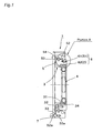
- FIGS. 1, 2, and 3 are a cross-sectional view, a right side end face view, and a left side end face view of a silk hat-type wave gear device of the present invention.
- FIG. 4 is a partial enlarged cross-sectional view thereof.
- the wave gear device 1 has an annular rigid internal gear 2, a silk hat-shaped flexible external gear 3 disposed coaxially inside the rigid internal gear, an elliptically contoured wave generator 4 fitted into the flexible external gear, and a cross roller bearing 5 for supporting the rigid internal gear 2 and the flexible external gear 3 in a relatively rotatable manner.
- the silk hat-shaped flexible external gear 3 has a cylindrical trunk 31, an annular diaphragm 32 that widens radially outward from one end of the trunk 31, an annular boss 33 formed in a continuous fashion on an outer peripheral edge of the diaphragm 32, and external teeth 34 formed on an outer peripheral surface of the opposite end side portion of the trunk 31.
- the trunk 31 of the flexible external gear 3 is coaxially enclosed in the cross roller bearing 5 with substantially the same width as the trunk 31.
- the cross roller bearing 5 has an annular inner ring 51, an annular outer ring 52, and a plurality of columnar rollers 54 rollably inserted in an alternately perpendicular manner into an annular raceway 53 with a rectangular cross section formed therebetween.
- the size of a toroidal end face 52a of the outer ring 52 corresponds to the size of a toroidal end face 33a of the boss 33 of the flexible external gear 3, and both these members are fastened with a fastening bolt 7 so that the toroidal end faces 52a and 33a thereof are in contact with each other.
- the rigid internal gear 2 and inner ring 51 of the present embodiment are composed of a toroidal composite member 6.
- the composite member 6 has an annular inner ring-forming member 61 that functions as the inner ring 51, and an annular internal teeth-forming member 62 that functions as the rigid internal gear 2 integrated with an inner peripheral surface of the inner ring-forming member 61.
- a raceway surface 61a is formed on an outer peripheral surface of the inner ring-forming member 61, and internal teeth 62a are formed on an inner peripheral surface of the internal teeth-forming member 62.
- the inner ring-forming member 61 is made of bearing steel, and the internal teeth-forming member 62 is formed from a ductile casting.
- the internal teeth-forming member 62 is integrated with the inner ring-forming member 61 by diffusion bonding.
- a portion of the flexible external gear 3 where the external teeth 34 are formed are elliptically flexed by the wave generator 4, and portions of the external teeth 34 positioned at both ends in a major axis direction of the elliptical shape thereof mesh with portions of the internal teeth 62a of the rigid internal gear 2.
- the rigid internal gear 2 composite member 6
- the wave generator 4 is rotated by a motor (not shown) or the like
- the meshing positions of the gears 2 and 3 move in a circumferential direction and reduced rotation is output from the flexible external gear 3.
- the rigid internal gear 2 and inner ring 51 are formed from the composite member 6, and the size and weight of the device can therefore be reduced. Since the rigid internal gear 2 is formed by the internal teeth-forming member 62 composed of a ductile casting in the composite member 6, the machining precision and abrasion resistance of the internal teeth 62a are high. Furthermore, since the inner ring 51 is formed by the inner ring-forming member 61 composed of bearing steel in the composite member 6, the rigidity and permissible moment load of the cross roller bearing 5 are high, and the rigidity and permissible moment load of the device 1 are therefore also high.
- the cross roller bearing 5 is used as the bearing for holding the gears 2 and 3 in a relatively rotatable manner, but ball bearings or the like may also be used.
Landscapes
- Engineering & Computer Science (AREA)
- General Engineering & Computer Science (AREA)
- Mechanical Engineering (AREA)
- Retarders (AREA)
- Mounting Of Bearings Or Others (AREA)
- Rolling Contact Bearings (AREA)
Claims (3)
- Wellgetriebevorrichtung, umfassend:ein ringförmiges starres Innenzahnrad (2, 62);ein ringförmiges flexibles Außenzahnrad (3);einen Wellengenerator (4) zum radialen Durchbiegen des flexiblen Außenzahnrads, um einen Teileingriff mit dem starren Innenzahnrad hervorzurufen und die in Eingriff befindlichen Stellen der Zahnräder in Umfangsrichtung zu bewegen; undein Lager (5) zum Lagern des starren Innenzahnrads und des flexiblen Außenzahnrads in relativ zueinander drehbarer Weise; wobeiein Außenring (52) des Lagers an dem flexiblen Außenzahnrad befestigt ist, undein Innenring (6) des Lagers ein zusammengesetztes Glied (6) ist, in welches das starre Innenzahnrad (2, 62) integriert ist, und wobeidas zusammengesetzte Glied aufweist: ein ringförmiges Innenringelement (51, 61), eine an der Außenumfangsfläche des Innenringelements ausgebildete Lauffläche (61a), ein integriert mit der Innenumfangsfläche des Innenringelements ausgebildetes ringförmiges Innenverzahnungs-Bildungselement (62) und an der Innenumfangsfläche des Innenverzahnungs-Bildungselements ausgebildete Innenzähne (62a); wobei das Innenverzahnungs-Bildungselement mit dem Innenringelement durch Diffusionsbindung integriert ist, dadurch gekennzeichnet, dass das Innenringelement aus Lagerstahl gebildet ist, und dass das Innenverzahnungs-Bildungselement durch Sphäroguss gebildet ist.
- Vorrichtung nach Anspruch 1, bei der das Lager (5) ein Kreuzwälzlager ist.
- Vorrichtung nach Anspruch 2, bei der das flexible Außenzahnrad (3) einen zylindrischen Schaft (31), eine ringförmige Membran, die sich von einem Ende des Schafts radial nach außen erstreckt, und einen ringförmigen Abschluss (33), der kontinuierlich anschließend an einen äußeren Umfangsrand der Membran ausgebildet ist, aufweist, wobei an der Außenumfangsfläche des Schafts Außenzähne (34) ausgebildet sind, und wobei das Lager koaxial außerhalb des Schafts angeordnet ist und der Außenring an dem Abschluss mit seiner ringförmigen Stirnfläche (52a) in Berührung mit der ringförmigen Stirnfläche des Abschlusses (33) befestigt ist.
Applications Claiming Priority (2)
| Application Number | Priority Date | Filing Date | Title |
|---|---|---|---|
| JP2004102989 | 2004-03-31 | ||
| JP2004102989A JP2005291237A (ja) | 2004-03-31 | 2004-03-31 | 軸受内輪一体型の内歯車を備えた波動歯車装置 |
Publications (2)
| Publication Number | Publication Date |
|---|---|
| EP1589261A1 EP1589261A1 (de) | 2005-10-26 |
| EP1589261B1 true EP1589261B1 (de) | 2007-05-16 |
Family
ID=34934583
Family Applications (1)
| Application Number | Title | Priority Date | Filing Date |
|---|---|---|---|
| EP05006894A Expired - Lifetime EP1589261B1 (de) | 2004-03-31 | 2005-03-30 | Spannungswellengetriebe mit einem Wälzlagerlaufring durch Diffusionsschweissen verbundenen Innenzahnrad |
Country Status (4)
| Country | Link |
|---|---|
| US (1) | US7165473B2 (de) |
| EP (1) | EP1589261B1 (de) |
| JP (1) | JP2005291237A (de) |
| DE (1) | DE602005001131T2 (de) |
Families Citing this family (27)
| Publication number | Priority date | Publication date | Assignee | Title |
|---|---|---|---|---|
| JP2009041623A (ja) * | 2007-08-07 | 2009-02-26 | Sumitomo Heavy Ind Ltd | 揺動内接遊星歯車構造 |
| KR101311413B1 (ko) * | 2010-11-02 | 2013-09-25 | 주식회사 에스비비테크 | 조화 감속기 |
| DE112011105253T5 (de) * | 2011-05-16 | 2014-02-13 | Harmonic Drive Systems Inc. | Einheitstyp-Wellgetriebe |
| KR101748177B1 (ko) * | 2011-07-29 | 2017-06-16 | 가부시키가이샤 하모닉 드라이브 시스템즈 | 복합 롤링 베어링부착 파동기어장치 |
| DE112012000394T5 (de) * | 2012-12-12 | 2014-08-28 | Harmonic Drive Systems Inc. | Wellgetriebeeinheit mit Eingangslagern |
| WO2014168545A1 (en) | 2013-04-09 | 2014-10-16 | Aktiebolaget Skf | Bearing component and its manufacturing method |
| SE537455C2 (sv) * | 2013-04-09 | 2015-05-05 | Skf Ab | Process för att erhålla en mekanisk komponent genom diffusionssvetsning |
| US9768664B2 (en) | 2015-05-21 | 2017-09-19 | The Boeing Company | Balanced eccentric gear design and method |
| DE102016217055B4 (de) * | 2015-09-10 | 2023-08-24 | Schaeffler Technologies AG & Co. KG | Getriebe mit elastischem Zahnrad |
| WO2017046927A1 (ja) * | 2015-09-17 | 2017-03-23 | 株式会社ハーモニック・ドライブ・システムズ | 波動歯車装置の波動発生器 |
| US10203022B2 (en) | 2015-11-04 | 2019-02-12 | The Boeing Company | Elliptically interfacing wobble motion gearing system and method |
| US10024391B2 (en) | 2016-01-06 | 2018-07-17 | The Boeing Company | Elliptically interfacing gearbox |
| US10574109B2 (en) | 2016-04-28 | 2020-02-25 | The Boeing Company | Permanent magnet biased virtual elliptical motor |
| US10215244B2 (en) | 2017-03-02 | 2019-02-26 | The Boeing Company | Elliptically interfacing gear assisted braking system |
| US10520063B2 (en) | 2017-04-21 | 2019-12-31 | The Boeing Company | Mechanical virtual elliptical drive |
| US10267383B2 (en) | 2017-05-03 | 2019-04-23 | The Boeing Company | Self-aligning virtual elliptical drive |
| JP6816304B2 (ja) | 2017-10-31 | 2021-01-20 | 株式会社ハーモニック・ドライブ・システムズ | ユニット構造の波動歯車装置 |
| KR102340718B1 (ko) | 2018-09-20 | 2021-12-16 | 가부시키가이샤 하모닉 드라이브 시스템즈 | 유닛형 파동기어장치 |
| CN111288077A (zh) * | 2018-12-10 | 2020-06-16 | 镁亚精密股份有限公司 | 减速传动轴承 |
| CN109356992B (zh) | 2018-12-11 | 2025-03-07 | 爱磁精密(深圳)有限公司 | 变形量可限制的双柔轮谐波减速机 |
| US10968969B2 (en) | 2019-03-18 | 2021-04-06 | The Boeing Company | Nutational braking systems and methods |
| US11459098B2 (en) | 2019-11-27 | 2022-10-04 | The Boeing Company | Variable speed transmission and related methods |
| JP7419193B2 (ja) * | 2020-08-27 | 2024-01-22 | 住友重機械工業株式会社 | 撓み噛合い式歯車装置 |
| CN112855761A (zh) * | 2021-02-09 | 2021-05-28 | 中山早稻田科技有限公司 | 一种内圈带齿的交叉滚子轴承 |
| WO2022249355A1 (ja) * | 2021-05-26 | 2022-12-01 | 株式会社ハーモニック・ドライブ・システムズ | 波動歯車装置 |
| KR20230000786A (ko) * | 2021-06-25 | 2023-01-03 | 주식회사 에스비비테크 | 파동 기어 장치 |
| CN113623365A (zh) * | 2021-08-16 | 2021-11-09 | 浙江环动机器人关节科技有限公司 | 一种超扁平三波谐波减速器 |
Family Cites Families (5)
| Publication number | Priority date | Publication date | Assignee | Title |
|---|---|---|---|---|
| US3147640A (en) * | 1960-04-13 | 1964-09-08 | United Shoe Machinery Corp | Wave generator for wave converter |
| EP0945650B1 (de) * | 1996-04-19 | 2005-02-02 | Harmonic Drive Systems Inc. | Elastisches zahnrad |
| JPH09291983A (ja) | 1996-04-30 | 1997-11-11 | Harmonic Drive Syst Ind Co Ltd | シルクハット型撓み噛み合い式歯車装置の可撓性外歯歯車の取付け構造 |
| JP2002307237A (ja) * | 2001-04-09 | 2002-10-23 | Harmonic Drive Syst Ind Co Ltd | 波動歯車装置の剛性内歯歯車の製造方法 |
| JP4390124B2 (ja) | 2001-05-22 | 2009-12-24 | 株式会社ハーモニック・ドライブ・システムズ | 軽量ベアリングの製造方法 |
-
2004
- 2004-03-31 JP JP2004102989A patent/JP2005291237A/ja active Pending
-
2005
- 2005-02-23 US US11/063,823 patent/US7165473B2/en not_active Expired - Lifetime
- 2005-03-30 EP EP05006894A patent/EP1589261B1/de not_active Expired - Lifetime
- 2005-03-30 DE DE602005001131T patent/DE602005001131T2/de not_active Expired - Lifetime
Also Published As
| Publication number | Publication date |
|---|---|
| DE602005001131T2 (de) | 2008-01-17 |
| DE602005001131D1 (de) | 2007-06-28 |
| US20050217420A1 (en) | 2005-10-06 |
| US7165473B2 (en) | 2007-01-23 |
| EP1589261A1 (de) | 2005-10-26 |
| JP2005291237A (ja) | 2005-10-20 |
Similar Documents
| Publication | Publication Date | Title |
|---|---|---|
| EP1589261B1 (de) | Spannungswellengetriebe mit einem Wälzlagerlaufring durch Diffusionsschweissen verbundenen Innenzahnrad | |
| US9309921B2 (en) | Internally-toothed gear unit with composite roller bearing, and wave gear device | |
| KR101651549B1 (ko) | 파동 기어 장치의 파동 발생기 | |
| KR101266266B1 (ko) | 감속장치 | |
| US8858383B2 (en) | Gear transmission | |
| US20160298746A1 (en) | Strain wave gearing, frictional engagement wave device, and wave generator | |
| JP2019148308A (ja) | 偏心揺動型減速装置 | |
| US20150167814A1 (en) | Wave gear device and flexible internally toothed gear | |
| JP2002031150A (ja) | 歯車装置ユニット | |
| US20130247716A1 (en) | Strain wave gear apparatus | |
| EP3680513A1 (de) | Wellenlager für wellenbewegungsgetriebe | |
| KR20180064976A (ko) | 휨맞물림식 기어장치 | |
| JP7450776B2 (ja) | 歯車装置 | |
| CN110230663B (zh) | 减速装置 | |
| KR20100075673A (ko) | 베벨 기어를 갖는 동력 전달 장치 | |
| JP2007016838A (ja) | シルクハット型波動歯車装置 | |
| EP0945650B1 (de) | Elastisches zahnrad | |
| CN110185745B (zh) | 齿轮装置系列及其构建方法、以及齿轮装置组的制造方法 | |
| EP4036441B1 (de) | Flachdehnungswellengetriebe | |
| EP2730805B1 (de) | Untersetzungsgetriebe | |
| JP3781315B2 (ja) | シルクハット型撓み噛み合い式歯車装置 | |
| JP2008025687A (ja) | 波動歯車装置用軸受 | |
| EP3936741B1 (de) | Planetengetriebe | |
| JPH05215191A (ja) | バックラッシュレス遊星歯車装置 | |
| JP2512462Y2 (ja) | 調和歯車変速装置の波動発生器 |
Legal Events
| Date | Code | Title | Description |
|---|---|---|---|
| PUAI | Public reference made under article 153(3) epc to a published international application that has entered the european phase |
Free format text: ORIGINAL CODE: 0009012 |
|
| AK | Designated contracting states |
Kind code of ref document: A1 Designated state(s): AT BE BG CH CY CZ DE DK EE ES FI FR GB GR HU IE IS IT LI LT LU MC NL PL PT RO SE SI SK TR |
|
| AX | Request for extension of the european patent |
Extension state: AL BA HR LV MK YU |
|
| 17P | Request for examination filed |
Effective date: 20051216 |
|
| GRAP | Despatch of communication of intention to grant a patent |
Free format text: ORIGINAL CODE: EPIDOSNIGR1 |
|
| AKX | Designation fees paid |
Designated state(s): DE |
|
| GRAS | Grant fee paid |
Free format text: ORIGINAL CODE: EPIDOSNIGR3 |
|
| GRAA | (expected) grant |
Free format text: ORIGINAL CODE: 0009210 |
|
| AK | Designated contracting states |
Kind code of ref document: B1 Designated state(s): DE |
|
| REF | Corresponds to: |
Ref document number: 602005001131 Country of ref document: DE Date of ref document: 20070628 Kind code of ref document: P |
|
| PLBE | No opposition filed within time limit |
Free format text: ORIGINAL CODE: 0009261 |
|
| STAA | Information on the status of an ep patent application or granted ep patent |
Free format text: STATUS: NO OPPOSITION FILED WITHIN TIME LIMIT |
|
| 26N | No opposition filed |
Effective date: 20080219 |
|
| REG | Reference to a national code |
Ref country code: DE Ref legal event code: R082 Ref document number: 602005001131 Country of ref document: DE Representative=s name: SCHMITT-NILSON SCHRAUD WAIBEL WOHLFROM PATENTA, DE |
|
| PGFP | Annual fee paid to national office [announced via postgrant information from national office to epo] |
Ref country code: DE Payment date: 20240122 Year of fee payment: 20 |
|
| REG | Reference to a national code |
Ref country code: DE Ref legal event code: R071 Ref document number: 602005001131 Country of ref document: DE |