EP1589791A2 - Dispositif pour court-circuiter une charge - Google Patents
Dispositif pour court-circuiter une charge Download PDFInfo
- Publication number
- EP1589791A2 EP1589791A2 EP05103018A EP05103018A EP1589791A2 EP 1589791 A2 EP1589791 A2 EP 1589791A2 EP 05103018 A EP05103018 A EP 05103018A EP 05103018 A EP05103018 A EP 05103018A EP 1589791 A2 EP1589791 A2 EP 1589791A2
- Authority
- EP
- European Patent Office
- Prior art keywords
- power supply
- voltage
- switching power
- load
- bridging
- Prior art date
- Legal status (The legal status is an assumption and is not a legal conclusion. Google has not performed a legal analysis and makes no representation as to the accuracy of the status listed.)
- Withdrawn
Links
- 238000009434 installation Methods 0.000 abstract description 23
- 238000005265 energy consumption Methods 0.000 abstract description 6
- 239000003990 capacitor Substances 0.000 description 27
- 238000009499 grossing Methods 0.000 description 14
- 239000007858 starting material Substances 0.000 description 7
- 238000005516 engineering process Methods 0.000 description 5
- 238000010276 construction Methods 0.000 description 3
- 230000005611 electricity Effects 0.000 description 3
- 229910052736 halogen Inorganic materials 0.000 description 3
- 150000002367 halogens Chemical class 0.000 description 3
- 230000002950 deficient Effects 0.000 description 2
- 238000010586 diagram Methods 0.000 description 2
- 241001136792 Alle Species 0.000 description 1
- 241001295925 Gegenes Species 0.000 description 1
- XEEYBQQBJWHFJM-UHFFFAOYSA-N Iron Chemical group [Fe] XEEYBQQBJWHFJM-UHFFFAOYSA-N 0.000 description 1
- 206010063493 Premature ageing Diseases 0.000 description 1
- 208000032038 Premature aging Diseases 0.000 description 1
- 239000004020 conductor Substances 0.000 description 1
- 238000001816 cooling Methods 0.000 description 1
- 230000003111 delayed effect Effects 0.000 description 1
- 230000001419 dependent effect Effects 0.000 description 1
- 230000010354 integration Effects 0.000 description 1
- 238000004519 manufacturing process Methods 0.000 description 1
- 230000033764 rhythmic process Effects 0.000 description 1
- 230000007704 transition Effects 0.000 description 1
- 230000001960 triggered effect Effects 0.000 description 1
- 238000011144 upstream manufacturing Methods 0.000 description 1
Images
Classifications
-
- H—ELECTRICITY
- H05—ELECTRIC TECHNIQUES NOT OTHERWISE PROVIDED FOR
- H05B—ELECTRIC HEATING; ELECTRIC LIGHT SOURCES NOT OTHERWISE PROVIDED FOR; CIRCUIT ARRANGEMENTS FOR ELECTRIC LIGHT SOURCES, IN GENERAL
- H05B41/00—Circuit arrangements or apparatus for igniting or operating discharge lamps
- H05B41/14—Circuit arrangements
- H05B41/26—Circuit arrangements in which the lamp is fed by power derived from DC by means of a converter, e.g. by high-voltage DC
- H05B41/28—Circuit arrangements in which the lamp is fed by power derived from DC by means of a converter, e.g. by high-voltage DC using static converters
- H05B41/282—Circuit arrangements in which the lamp is fed by power derived from DC by means of a converter, e.g. by high-voltage DC using static converters with semiconductor devices
- H05B41/285—Arrangements for protecting lamps or circuits against abnormal operating conditions
- H05B41/2851—Arrangements for protecting lamps or circuits against abnormal operating conditions for protecting the circuit against abnormal operating conditions
- H05B41/2853—Arrangements for protecting lamps or circuits against abnormal operating conditions for protecting the circuit against abnormal operating conditions against abnormal power supply conditions
-
- H—ELECTRICITY
- H05—ELECTRIC TECHNIQUES NOT OTHERWISE PROVIDED FOR
- H05B—ELECTRIC HEATING; ELECTRIC LIGHT SOURCES NOT OTHERWISE PROVIDED FOR; CIRCUIT ARRANGEMENTS FOR ELECTRIC LIGHT SOURCES, IN GENERAL
- H05B41/00—Circuit arrangements or apparatus for igniting or operating discharge lamps
- H05B41/14—Circuit arrangements
- H05B41/26—Circuit arrangements in which the lamp is fed by power derived from DC by means of a converter, e.g. by high-voltage DC
- H05B41/28—Circuit arrangements in which the lamp is fed by power derived from DC by means of a converter, e.g. by high-voltage DC using static converters
- H05B41/288—Circuit arrangements in which the lamp is fed by power derived from DC by means of a converter, e.g. by high-voltage DC using static converters with semiconductor devices and specially adapted for lamps without preheating electrodes, e.g. for high-intensity discharge lamps, high-pressure mercury or sodium lamps or low-pressure sodium lamps
- H05B41/292—Arrangements for protecting lamps or circuits against abnormal operating conditions
- H05B41/2921—Arrangements for protecting lamps or circuits against abnormal operating conditions for protecting the circuit against abnormal operating conditions
- H05B41/2923—Arrangements for protecting lamps or circuits against abnormal operating conditions for protecting the circuit against abnormal operating conditions against abnormal power supply conditions
-
- H—ELECTRICITY
- H05—ELECTRIC TECHNIQUES NOT OTHERWISE PROVIDED FOR
- H05B—ELECTRIC HEATING; ELECTRIC LIGHT SOURCES NOT OTHERWISE PROVIDED FOR; CIRCUIT ARRANGEMENTS FOR ELECTRIC LIGHT SOURCES, IN GENERAL
- H05B41/00—Circuit arrangements or apparatus for igniting or operating discharge lamps
- H05B41/14—Circuit arrangements
- H05B41/26—Circuit arrangements in which the lamp is fed by power derived from DC by means of a converter, e.g. by high-voltage DC
- H05B41/28—Circuit arrangements in which the lamp is fed by power derived from DC by means of a converter, e.g. by high-voltage DC using static converters
- H05B41/295—Circuit arrangements in which the lamp is fed by power derived from DC by means of a converter, e.g. by high-voltage DC using static converters with semiconductor devices and specially adapted for lamps with preheating electrodes, e.g. for fluorescent lamps
-
- H—ELECTRICITY
- H05—ELECTRIC TECHNIQUES NOT OTHERWISE PROVIDED FOR
- H05B—ELECTRIC HEATING; ELECTRIC LIGHT SOURCES NOT OTHERWISE PROVIDED FOR; CIRCUIT ARRANGEMENTS FOR ELECTRIC LIGHT SOURCES, IN GENERAL
- H05B41/00—Circuit arrangements or apparatus for igniting or operating discharge lamps
- H05B41/14—Circuit arrangements
- H05B41/26—Circuit arrangements in which the lamp is fed by power derived from DC by means of a converter, e.g. by high-voltage DC
- H05B41/28—Circuit arrangements in which the lamp is fed by power derived from DC by means of a converter, e.g. by high-voltage DC using static converters
- H05B41/295—Circuit arrangements in which the lamp is fed by power derived from DC by means of a converter, e.g. by high-voltage DC using static converters with semiconductor devices and specially adapted for lamps with preheating electrodes, e.g. for fluorescent lamps
- H05B41/298—Arrangements for protecting lamps or circuits against abnormal operating conditions
- H05B41/2981—Arrangements for protecting lamps or circuits against abnormal operating conditions for protecting the circuit against abnormal operating conditions
- H05B41/2983—Arrangements for protecting lamps or circuits against abnormal operating conditions for protecting the circuit against abnormal operating conditions against abnormal power supply conditions
Definitions
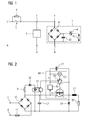
- FIG 1 a corresponding installation design is shown.
- the circuit has a mains phase L over one Installation switch 1 to a first terminal a of a load 4th connected.
- the load 4 may be act an energy-saving lamp.
- the load 4 (energy saving lamp) is connected to the N-conductor with its second terminal b and thus closes the circuit.
- the switching device 1 is bridged by a consumer element 2 high impedance.
- a bridging device 3 Parallel to the load 4 is a bridging device 3 with their terminals c and d connected to the terminals a, b of the load 4.
- the bridging device 3 is closed the switching device 1 switchable to the mains voltage and by opening the switching device 1 from the mains voltage separable. With closed switching device 1 has the Bypass device 3 high resistance, whereas when the switching device 1 is open, the bridging device 3 has a low resistance.
- the energy-saving lamp (load 4) shown in FIG. 1 comprises a bridge rectifier 41 and a smoothing capacitor 42, which is arranged parallel to the fluorescent lamp 43.
- a diac 44 is arranged, which upon reaching a certain Charging voltage of the smoothing capacitor 42 (about 30 V) the Igniting the fluorescent tube 43 causes.
- glow lamps various display elements (eg light-emitting diodes), power supplies with low-power transformer, Switching power supplies for mains voltage and capacitor power supplies and resistor power supplies.
- switches switching power supplies for mains voltage and capacitor power supplies and resistor power supplies.
- Such components can also be integrated in two-wire switches.
- Loads caused by the high-impedance bridging of the switching device are endangered by a consumer element, can, for example, energy-saving lamps, fluorescent lamps with classic ballast, fluorescent lamps with electronic Ballast and low-voltage halogen lamps with certain electronic transformers (e.g., non-dimmable types) and staircase lighting time switch (control input) or remote switch be.
- energy-saving lamps fluorescent lamps with classic ballast
- Warm start lamps would be due to the delayed lamp ignition in principle on a high-impedance bridged switching device without further action, however, this mode becomes not favored by the lamp manufacturers, as the Spiral in a predetermined by the charging cycle of the smoothing capacitor Rhythm be heated up again and again. A premature Aging of the warm start lamp would be the result.
- the operation of warm start lamps is indicated on page 30 (also high impedance) bridged switching devices as not permissible.
- Fluorescent lamps with classic ballast are using a starter (glow starter, glow starter, electronic Starters and others). In the off state practically only the starter resistor works. Glimmerstarter and Some electronic starters are relatively high impedance, so that in the off state of the switching device, the current flow initiate ignition attempts via the consumer element can. The fluorescent lamp flashes briefly, but can due to the limited current flow does not shine permanently and goes out again.
- Fluorescent lamps with electronic ballast today Type have a bridge rectifier with smoothing capacitor at the entrance.
- the power on reset only appears when almost no voltage is applied to the smoothing capacitor.
- a high-resistance bridged one Turn-on the voltage at the smoothing capacitor can not go to zero in order to be under the power On reset threshold can enter the fluorescent lamp with electronic ballast with the replaced new Do not start the fluorescent tube anymore.
- a bridging device parallel to Load (energy-saving lamp, fluorescent lamp, staircase lighting timer) arranged a bridging device.
- the bridging device takes over in the switched off state Switching device (switching device open) the larger Part of the current flow, so that the voltage drop across the Load is kept as low as possible. Is the Switching device in the on state (switching device closed), then the bridging device must however can carry the full mains voltage, with one as possible low energy consumption is desired.
- an incandescent lamp serve as a bridging device.
- this application is i.a. because of the additional energy consumption disadvantageous.
- a bridging device can also be a capacitor for Use come. However, this is due to the required high Dielectric strength (mains voltage) relatively large volume. If the consumer element requires a relatively large amount of electricity, the Capacitor have a relatively high capacitance value. Of the Capacitor would then either be oversized or but adapted to each individual application.
- PTC thermistors PTC Positive Temperature Coefficient
- the PTC thermistor operated at full mains voltage and heats up accordingly on, resulting in a corresponding energy consumption arises.
- the PTC thermistor virtually ineffective until it cools down, so that after each switching off the switching device for the Duration of the cooling time the aforementioned problems occur.
- All known bridging devices have a steady (continuous) transition between the low and the high resistance of their internal resistance.
- a staircase lighting timer with integrated bridging module known, to which several installation buttons with glow lamps are connected can be. Depending on the amount of voltage applied at the bridging module this is low impedance or high impedance.
- the bypass module has a bridge rectifier circuit on, the DC output with an electronic bistable circuit is connected.
- Object of the present invention is therefore, the Application of a high-resistance bridged installation switch to expand.
- this object is achieved by a bridging device for bridging an electrical load with a connection device for excluding the lock-up device parallel to the electrical load and one electrical impedance coupled to the terminal device is, as well as a switching power supply, with which the electrical Impedance in a predeterminable manner to the connection device is switchable.
- bridging device With the bridging device according to the invention it is thus possible, different load types of the installation technology to operate even if the installation switch in Circuit is bridged high impedance.
- you can high-impedance bridged switches thus energy-saving lamps, Fluorescent lamps with classic ballast, fluorescent lamps with electronic ballast, low voltage halogen lights with certain electronic transformers (e.g. non-dimmable types), staircase lighting timer with control input and the like.
- This can be conventional Installation switch or installation button with Glimmlampen, various display elements, a power supply with Low power transformer, a switching power supply for mains voltage, a capacitor power supply, a resistor power supply, and the like be bridged as a high-impedance consumer element.
- These components can also be used in electronic two-wire switches be integrated.
- the switching power supply is the lock-up device according to the present invention in its function interruptible. This is an operation in the so-called burst mode possible.
- the switching power supply can also have a free-running Oscillator, a driver and a switching transistor include.
- a free-running Oscillator e.g., a driver and a switching transistor include.
- the electrical impedance can be an inductance and a have ohmic resistance. This allows the power consumption of the switch connected in parallel with the consumer element take exactly into account.
- connection device and the Switching power supply including electrical impedance a full wave rectifier be switched.
- the circuit of the lock-up device polarity independent.
- the switching power supply including a constant voltage source for the switching power supply integrated in a chip. This can be done a simplified embodiment of the circuit of the lock-up device to reach.
- a bridging module in version as switching power supply with wide-range input voltage (AC / DC converter) with a connected Base load proposed on the secondary side.
- the input voltage range should have an extended range of 30 to 253 Cover V AC.
- the switching power supply is for a Functional operation designed in so-called burst mode, what indicates that its function is interrupted as needed can.
- the function is interrupted whenever the full bridge voltage is present at the bypass module is present, d. H. when the switch 1 and the load 4 are turned on are (see FIG 1).
- the controller is a voltage sensor needed. Regarding the energy balance appears in this state the base load of the switching power supply is no longer what to an energy saving leads.
- FIG. 1 A schematic diagram of the preferred lock-up device is shown in FIG.
- the terminals c, d of the bypass module be compliant FIG 1 connected in parallel to the load 4.
- the switch 1 When the switch 1 is turned off, the to the Terminals c, d voltage applied via the fuse F1 to the Bridge rectifier V1 out, rectified and to the Capacitor C1 applied.
- the capacitor C1 charges.
- the constant voltage source N1 which is connected to an output terminal of the bridge rectifier V1 is active, and the switching network starts.
- This consists from a series circuit of a free-running oscillator N2, a driver N3 and a switching transistor T1, preferably a MOSFET.
- the drain contact D of the switching transistor T1 is also connected to the output terminal of the bridge rectifier V1 connected to the also the constant voltage source N1 is connected.
- the source contact S of Switching transistor T1 is connected in series with a coil or inductance L1 and a load resistor R2 connected. Parallel to the series connection is a flyback diode V3.
- the source contact S of the switching transistor T1 is over a capacitor C2 to the input of the free-running oscillator N2 connected.
- the inductance L1 is through the current through the load resistor R2 magnetically charged.
- the The flyback diode V3 becomes conductive and the energy from L1 changes over unload the load resistor.
- N2 represents this in known Make a circuit-adapted pulse-pause ratio safe: short switch-on pulses with longer ones Off times for T1 alternate periodically, with the length being the turn-on of the voltage to C1 made dependent becomes. The higher the voltage across the capacitor C1, the shorter the charging pulses for L1.
- the circuit of the bridging module is through the bridge rectifier V1 (full wave rectifier) polarity independent. Since there are two-wire electronic switches, the for the supply of their own electronics a half-wave rectification use that is of vital advantage for the Construction of an installation.
- V1 full wave rectifier
- a control loop with Inclusion of the energy requirement provided on the load resistor R2 be.
- the voltage must be applied to R2 by means of parallel connection be smoothed a capacitor.
- a voltage detector watch the voltage on this capacitor and controls the lock input of the driver N3, usually also via an optocoupler.
- the energy supply or the current through the consumer 2 are finer graded. There the switching power supply works at high voltage even at the terminals, But this results in the same energy loss at R2 as in FIG. 2, given by the consumer 2 needed Electricity.
- Another embodiment may be that the Components of the switching power supply including the constant voltage source N1 integrated in a chip N4 (see FIG are.
- An example of this is the building block TNY 253 of the Fa. "power integration". It simplifies the execution with it the circuit.
- circuit is complete in SMD assembly possible. It requires the smallest volume in a flat design.
Landscapes
- Circuit Arrangement For Electric Light Sources In General (AREA)
- Dc-Dc Converters (AREA)
- Direct Current Feeding And Distribution (AREA)
- Keying Circuit Devices (AREA)
Applications Claiming Priority (2)
| Application Number | Priority Date | Filing Date | Title |
|---|---|---|---|
| DE102004019600 | 2004-04-22 | ||
| DE200410019600 DE102004019600B4 (de) | 2004-04-22 | 2004-04-22 | Überbrückungsvorrichtung zum Überbrücken einer elektrischen Last |
Publications (2)
| Publication Number | Publication Date |
|---|---|
| EP1589791A2 true EP1589791A2 (fr) | 2005-10-26 |
| EP1589791A3 EP1589791A3 (fr) | 2008-08-06 |
Family
ID=34939319
Family Applications (1)
| Application Number | Title | Priority Date | Filing Date |
|---|---|---|---|
| EP05103018A Withdrawn EP1589791A3 (fr) | 2004-04-22 | 2005-04-15 | Dispositif pour court-circuiter une charge |
Country Status (2)
| Country | Link |
|---|---|
| EP (1) | EP1589791A3 (fr) |
| DE (1) | DE102004019600B4 (fr) |
Families Citing this family (1)
| Publication number | Priority date | Publication date | Assignee | Title |
|---|---|---|---|---|
| DE102009050203B4 (de) * | 2009-10-21 | 2012-05-03 | Osram Ag | Vorrichtung mit einer Unterdrückungsschaltung eines Restlichts |
Citations (2)
| Publication number | Priority date | Publication date | Assignee | Title |
|---|---|---|---|---|
| CH658340A5 (en) | 1982-07-29 | 1986-10-31 | Feller Ag | Circuit arrangement for driving a relay by means of push buttons which are illuminated by glow lamps |
| CA2225005A1 (fr) | 1997-12-17 | 1999-06-17 | Gelcore Llc | Voyant del avec circuit indicateur de pannes et dont l'impedance varie |
Family Cites Families (7)
| Publication number | Priority date | Publication date | Assignee | Title |
|---|---|---|---|---|
| US4677467A (en) * | 1985-04-16 | 1987-06-30 | General Electric Company | CATV addressable converter with multi-purpose, bi-directional serial digital data port |
| NL8702489A (nl) * | 1987-10-19 | 1989-05-16 | Philips Nv | Gelijkstroom-wisselstroom omzetter voor het ontsteken en voeden van een gasontladingslamp. |
| JP2991893B2 (ja) * | 1993-05-31 | 1999-12-20 | 富士通株式会社 | 発光素子の駆動回路及びこれを用いた光増幅中継器 |
| DE4343219C1 (de) * | 1993-12-17 | 1994-12-15 | Legrand Gmbh | Kurzschlußfester Treppenlichtzeitschalter |
| US6452343B2 (en) * | 1999-11-17 | 2002-09-17 | Koninklijke Philips Electronics N.V. | Ballast circuit |
| WO2001060128A1 (fr) * | 2000-02-10 | 2001-08-16 | Koninklijke Philips Electronics N.V. | Circuit de protection comprenant une resistance a coefficient de temperature negatif |
| US7068022B2 (en) * | 2001-11-13 | 2006-06-27 | Power Integrations, Inc. | Method and apparatus for a switch mode power supply that generates a high pulse width modulation gain while maintaining low noise sensitivity |
-
2004
- 2004-04-22 DE DE200410019600 patent/DE102004019600B4/de not_active Expired - Fee Related
-
2005
- 2005-04-15 EP EP05103018A patent/EP1589791A3/fr not_active Withdrawn
Patent Citations (2)
| Publication number | Priority date | Publication date | Assignee | Title |
|---|---|---|---|---|
| CH658340A5 (en) | 1982-07-29 | 1986-10-31 | Feller Ag | Circuit arrangement for driving a relay by means of push buttons which are illuminated by glow lamps |
| CA2225005A1 (fr) | 1997-12-17 | 1999-06-17 | Gelcore Llc | Voyant del avec circuit indicateur de pannes et dont l'impedance varie |
Also Published As
| Publication number | Publication date |
|---|---|
| DE102004019600B4 (de) | 2008-04-17 |
| EP1589791A3 (fr) | 2008-08-06 |
| DE102004019600A1 (de) | 2005-11-17 |
Similar Documents
| Publication | Publication Date | Title |
|---|---|---|
| DE69628739T2 (de) | Steuerung und überwachung von dimmbaren vorschaltgeräten mit breitem beleuchtungshub | |
| EP0800335B1 (fr) | Circuit pour alimenter des lampes électriques | |
| EP0264765A2 (fr) | Disposition de circuit pour la mise en oeuvre de lampe à incandescence halogène basse tension | |
| EP1231821B1 (fr) | Ballast pour lampes électriques | |
| DE19612170A1 (de) | Schaltungsanordnung zum Betrieb von elektrischen Lampen und Betriebsverfahren für elektrische Lampen | |
| DE19635686A1 (de) | Vorschaltanordnung für Leuchtstofflampen mit wählbaren Leistungspegeln | |
| DE10297588T5 (de) | Halogen-Grundkonverter-IC | |
| DE3901111A1 (de) | Schaltungsanordnung zum betrieb von entladungslampen | |
| EP1467474B1 (fr) | Circuit d'interface pour opérer des charges capacitives | |
| EP0439240A2 (fr) | Ballast électronique | |
| DE69513646T2 (de) | Schaltung zum Betreiben von Entladungslampen mit vorgeheizten Wendeln | |
| EP0319003B1 (fr) | Dispositif d'alimentation pour une lampe à décharge basse ou haute pression, lampe à vapeur de mercure ou analogue | |
| DE102004019600B4 (de) | Überbrückungsvorrichtung zum Überbrücken einer elektrischen Last | |
| DE4201744A1 (de) | Zusatzschaltung in einem schaltnetzteil fuer niedervolthalogenlampen | |
| EP2103192B1 (fr) | Montage électrique et procédé pour allumer et faire fonctionner une ou plusieurs lampes à décharge | |
| EP0629104B1 (fr) | Circuit pour limiter le courant continu decrête et/ou le courant d'appel par l'allumage d'une lampe à décharge | |
| DE4406000A1 (de) | Dimmerschaltung für Gasentladungslampen mit elektronischen Vorschaltgeräten | |
| DE4325050C2 (de) | Schaltungsanordnung zum Starten einer vorheizbaren Entladungslampe | |
| DE102004037389A1 (de) | Verfahren zur Ansteuerung einer eine Leuchtstofflampe aufweisenden Last zur Optimierung des Zündvorganges | |
| EP0682465B1 (fr) | Circuit pour alimenter des lampes à incandescence | |
| DE2721253A1 (de) | Anordnung zum starten und betreiben von leuchtstofflampen | |
| DE10100037A1 (de) | Schaltungsanordnung zum Betrieb von elektrischen Lampen | |
| WO2006122525A1 (fr) | Ballast electronique destine a une lampe a decharge gazeuse basse pression comportant un microcontroleur | |
| DE10006136A1 (de) | Betriebsschaltung für Entladungslampen mit umschaltbaren Betriebszuständen für den Einsatz mit Zeitschaltautomaten | |
| DE29806567U1 (de) | Beleuchtungsvorrichtung |
Legal Events
| Date | Code | Title | Description |
|---|---|---|---|
| PUAI | Public reference made under article 153(3) epc to a published international application that has entered the european phase |
Free format text: ORIGINAL CODE: 0009012 |
|
| AK | Designated contracting states |
Kind code of ref document: A2 Designated state(s): AT BE BG CH CY CZ DE DK EE ES FI FR GB GR HU IE IS IT LI LT LU MC NL PL PT RO SE SI SK TR |
|
| AX | Request for extension of the european patent |
Extension state: AL BA HR LV MK YU |
|
| PUAL | Search report despatched |
Free format text: ORIGINAL CODE: 0009013 |
|
| AK | Designated contracting states |
Kind code of ref document: A3 Designated state(s): AT BE BG CH CY CZ DE DK EE ES FI FR GB GR HU IE IS IT LI LT LU MC NL PL PT RO SE SI SK TR |
|
| AX | Request for extension of the european patent |
Extension state: AL BA HR LV MK YU |
|
| 17P | Request for examination filed |
Effective date: 20080911 |
|
| 17Q | First examination report despatched |
Effective date: 20081121 |
|
| AKX | Designation fees paid |
Designated state(s): AT BE BG CH CY CZ DE DK EE ES FI FR GB GR HU IE IS IT LI LT LU MC NL PL PT RO SE SI SK TR |
|
| RAP1 | Party data changed (applicant data changed or rights of an application transferred) |
Owner name: SIEMENS AKTIENGESELLSCHAFT |
|
| STAA | Information on the status of an ep patent application or granted ep patent |
Free format text: STATUS: THE APPLICATION IS DEEMED TO BE WITHDRAWN |
|
| 18D | Application deemed to be withdrawn |
Effective date: 20131101 |