EP1591014A2 - Cutting tool for cutting up slaughtered animals - Google Patents
Cutting tool for cutting up slaughtered animals Download PDFInfo
- Publication number
- EP1591014A2 EP1591014A2 EP05005926A EP05005926A EP1591014A2 EP 1591014 A2 EP1591014 A2 EP 1591014A2 EP 05005926 A EP05005926 A EP 05005926A EP 05005926 A EP05005926 A EP 05005926A EP 1591014 A2 EP1591014 A2 EP 1591014A2
- Authority
- EP
- European Patent Office
- Prior art keywords
- cutting blade
- protective hood
- cutting
- drive
- drive unit
- Prior art date
- Legal status (The legal status is an assumption and is not a legal conclusion. Google has not performed a legal analysis and makes no representation as to the accuracy of the status listed.)
- Withdrawn
Links
Images

Classifications
-
- A—HUMAN NECESSITIES
- A22—BUTCHERING; MEAT TREATMENT; PROCESSING POULTRY OR FISH
- A22B—SLAUGHTERING
- A22B5/00—Accessories for use during or after slaughtering
- A22B5/0017—Apparatus for cutting, dividing or deboning carcasses
- A22B5/0023—Cutting open the abdominal cavity of a carcass
Definitions
- the invention relates to a cutting tool for cutting of slaughter animals according to the preamble of claim 1.
- the object underlying the invention is to the protection of the drive of the circular formed To ensure cutting tool from contamination and that Pressing on the skin of the slaughtered animal into which the Cutting tool cuts into the cutting tool To improve as simple as possible construction.
- the prior art still has the following problem.
- the slaughtered animal becomes it in its position relative to the tool to stabilize, from the tool deflected from the vertical.
- The must Bearing the tool take up considerable forces, especially because up to 650 slaughtered animals per Hour to be opened in this way.
- the task is thus also to make the arrangement so that at least one Part of the forces are absorbed elsewhere.
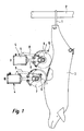
- FIG. 1 indicates at the hind legs by means of a hook 1 a slaughtered animal 3 suspended from a transport device 2, for example, a pig.
- a cutting tool generally designated 4
- a drive unit 5 u. a. containing one Electric motor
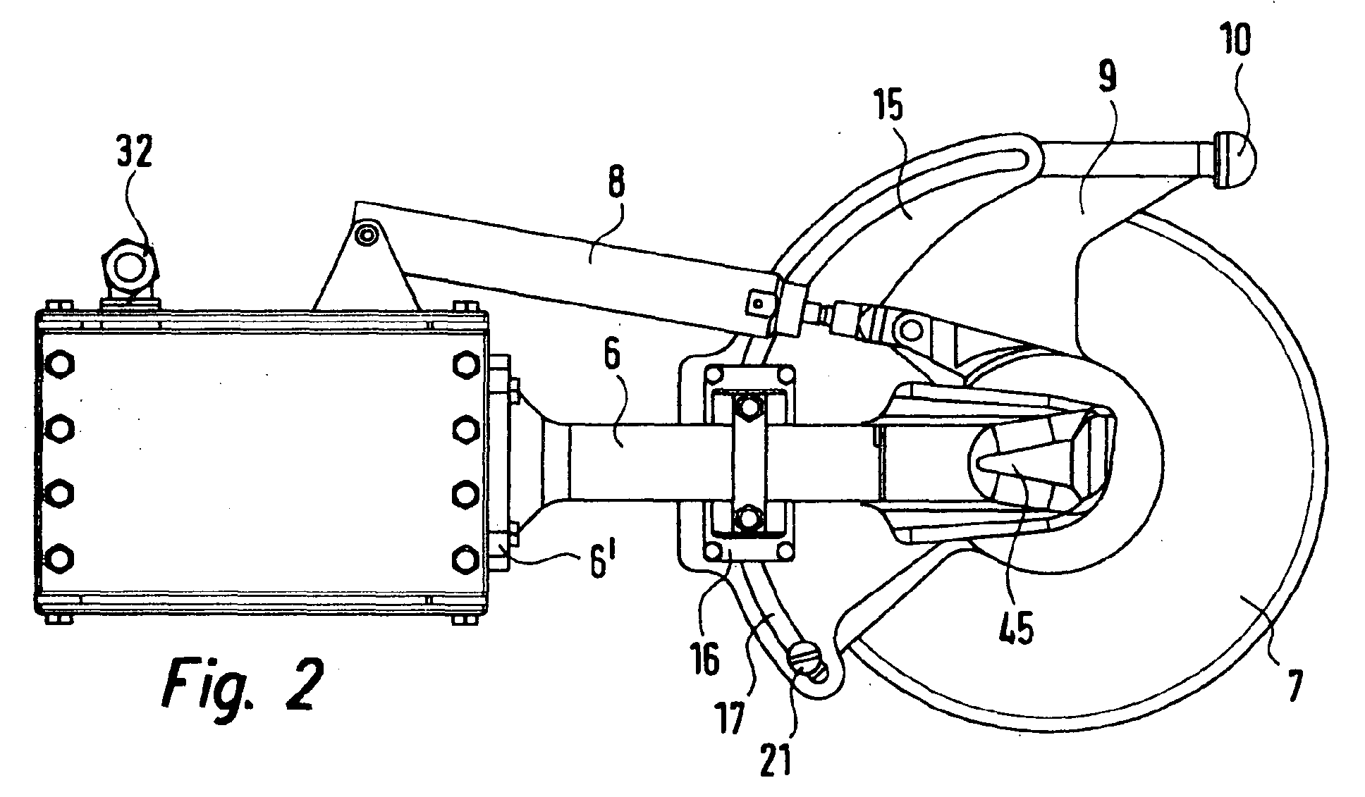
- a boom 6 a means of said Electric motor driven cutting blade 7 (for example a saw) and one by means of a piston / cylinder arrangement 8 between the two end positions I and II adjustable protective hood 9 has.
- the cutting tool is for attachment to a conventional multi-axis robot designed, to which the drive unit 5 is connected and can be screwed on.
- the boom 6 is by means Flange 6 'attached to the drive unit 5.
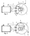
- FIG. 2 shows the guard 9 in the retracted position I according to FIG. 1;
- Figure 3 shows the protective hood 9 in full extended position II according to Figure 1, in which the Andschreib stresses 10 extends vertically downwards.
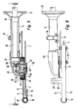
- FIG. 2 and 3 corresponds to the boom 6, a guide plate 15th screwed on, with the help of a Fixing block 16 (see also Figure 14).
- the Guide plate 15 has a recess formed as an incision Guideway 17, concentric with the axis of rotation 18th a circular rotary driven cutting tool 7 runs, but has a larger diameter than this.
- this guideway guide pins 19, 20 are guided, screwed to the protective hood 9 by means of screws 21 are.
- the guide plate 15 takes over the pins 19, 20 a part of the forces on the Cutting act on the guide body 10 and relieved thus the storage.
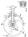
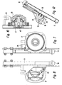
- the boom is the sixth at the same time housing a shaft 35 which in the boom. 6 is mounted by means of bearings 36, 37.
- the shaft 35 is from the electric motor provided in the drive unit 5 (not shown) driven.
- One at the end of the wave provided pinion 38 engages in a pinion 39, the on a drive pin 40 sits.
- On the drive pin 40th is by means of screw 41, the cutting blade 7 centric clamped.
- the boom 6 is in a housing 45 via, in in which the aforementioned components are arranged.
- the housing 45 has a ring 46th carries, the drive pin 40 with low radial Distance surrounds and on the means of screws 47 a annular cover plate 48 is screwed. Between the Cover plate 48 and a disc-shaped projection 49 of the Ring 46 is rotatable relative to these parts another ring 42, with the boom 6 facing Side plate 11 of the protective cover 9 by means of screws 12 is screwed.
- the bolted to the protective hood 9 Ring 42 thus rotates with the protective cover 9 in the between extension 49 and cover plate 48 formed groove 43rd
- the boom 6 facing away from side plate 13th extends so far to the axis of rotation 18 out that they outer circumference 7 'of the cutting blade 7 overlaps.
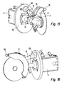
- Figures 15 and 16 show another Embodiment
- the embodiment according to Figures 1 - 14 is basically the same, but with the additional measure that between drive unit 5 and the cutting blade 7 bearing parts a Schmutzab utilizat plate 50 is arranged to the Drive unit to protect against contamination.
- This is provided with two openings. The one opening is in the Figures 15, 16 through the flange 6 'of the boom. 6 covered. Through this opening, the shaft 35 extends therethrough. Through the opening 51, the piston / cylinder arrangement extends 8 through. At this is a bellows 55 provided to prevent through the opening 51 Dirt passes through.
- the protective hood 9 extends over a sector of more as 90 °, in the exemplary embodiment about 135 ° to the to ensure described dirt repellency.
Landscapes
- Life Sciences & Earth Sciences (AREA)
- Engineering & Computer Science (AREA)
- Food Science & Technology (AREA)
- Processing Of Meat And Fish (AREA)
Abstract
Beschrieben wird ein Schneidwerkzeug zum Aufschneiden eines
Schlachttieres (3) mit einem kreisförmigen von einer
Antriebseinheit (5) rotierend angetriebenen Schneidmesser
(7) sowie einem in seiner Stellung gegenüber dem
Schneidmesser veränderbaren Andrückkörper (10), und einer
das Schneidmesser zumindest teilweise überdeckenden
verstellbaren Schutzhaube (9). Der Antrieb des
Schneidmessers (7) wird durch eine Welle (35) und
Antriebsmittel (38, 39, 45) gebildet, die in einem an der
Antriebseinheit (5) vorgesehenen Ausleger (6) angeordnet
sind. Die Schutzhaube (9) ist an einer auf dem Ausleger (6)
angeordneten Führungsplatte (15) um die Drehachse (18) des
Schneidmessers (7) mittels einer an ihr angreifenden
Kolbenstange (31) einer an der Antriebseinheit (5)
angebrachten Kolben-/Zylinderanordnung (8) drehbar. Die den
Antriebsmitteln (38, 39, 40, 45) zugewandte Seitenplatte
(11) der Schutzhaube (9) weist einen Ring (42) auf, der
gegenüber einem am Gehäuse (45) der Antriebsmittel
angeordneten Ring (46), drehbar ist.
Description
Die Erfindung betrifft ein Schneidwerkzeug zum Aufschneiden
von Schlachttieren nach dem Oberbegriff des Anspruches 1.The invention relates to a cutting tool for cutting
of slaughter animals according to the preamble of
Bei einer bekannten Vorrichtung dieser Art (vgl. EP 0 594 791 B1) ist der Schutz des Antriebs des Schneidmessers vor Verschmutzung durch beim Schneidvorgang entstehende tierische Abfälle nicht ausreichend gewährleistet.In a known device of this kind (see EP 0 594 791 B1) is the protection of the drive of the cutting blade Contamination caused by the cutting process Animal waste is not sufficiently guaranteed.
Die der Erfindung zugrunde liegende Aufgabe besteht darin, den Schutz des Antriebs des kreisförmig ausgebildeten Schneidwerkzeugs vor Verschmutzung zu gewährleisten und das Andrücken der Haut des Schlachttieres, in die das Schneidwerkzeug einschneidet, an das Schneidwerkzeug bei möglichst einfachem Aufbau zu verbessern.The object underlying the invention is to the protection of the drive of the circular formed To ensure cutting tool from contamination and that Pressing on the skin of the slaughtered animal into which the Cutting tool cuts into the cutting tool To improve as simple as possible construction.
Beim Stand der Technik tritt noch folgendes Problem auf. Bei der Führung des Schnitts wird das Schlachttier, um es in seiner Lage relativ zum Werkzeug zu stabilisieren, von dem Werkzeug aus der Vertikalen ausgelenkt. Dabei muss die Lagerung des Werkzeugs erhebliche Kräfte aufnehmen, insbesondere deshalb, weil bis zu 650 Schlachttiere pro Stunde auf diese Weise geöffnet werden. Aufgabe ist es somit auch, die Anordnung so zu treffen, das zumindest ein Teil der Kräfte anderweitig aufgenommen werden.The prior art still has the following problem. When leading the cut, the slaughtered animal becomes it in its position relative to the tool to stabilize, from the tool deflected from the vertical. The must Bearing the tool take up considerable forces, especially because up to 650 slaughtered animals per Hour to be opened in this way. The task is thus also to make the arrangement so that at least one Part of the forces are absorbed elsewhere.
Die Lösung dieser Aufgabe erfolgt mit den im Anspruch 1
angegebenen Mitteln. Vorteilhafte Weiterbildungen der
Erfindung sind in den Unteransprüchen definiert.The solution of this object is achieved with the in
Ausführungsbeispiele der Erfindung und ihrer vorteilhaften Weiterbildungen werden im Folgenden anhand der beigefügten Zeichnungen beschrieben. Es stellen dar:
Figur 1- eine schematische Darstellung eines Ausführungsbeispiels an einem Schlachttier;
Figur 2- das Ausführungsbeispiel in Stellung I nach
Figur 1; - Figur 3
- das Ausführungsbeispiel in Stellung II nach
Figur 1; - Figur 4
- eine Seitenansicht (Rückansicht, wenn bezogen auf Fig. 1 - 3) des Ausführungsbeispiels;
Figur 5- eine Ansicht in Richtung der Pfeile Linie V-V in Figur 4;
Figur 6- eine Ansicht in Richtung der Pfeile VI-VI in
Figur 5; Figur 7- eine Ansicht in Richtung der Pfeile VII-VII in Figur 4;
Figur 8- ein Ansicht in Richtung der Pfeile VIII-VIII in Figur 4;
Figur 9- eine Ansicht in Richtung der Pfeile IX-IX in Figur 4;
Figur 10- eine Ansicht in Richtung der.Pfeile X-X in Figur 4;
Figur 11- eine Ansicht in Richtung der Pfeile XI-XI in Figur 4;
Figur 12- eine Ansicht in Richtung der Pfeile XII-XII in
Figur 6; Figur 13- eine Ansicht in Richtung der Pfeile XIII-XIII in Figur 4;
- Figur 14
- eine Ansicht entlang der Pfeile XIV-XIV in
Figur 6; - 15 und 16
- ein weiteres Ausführungsbeispiel in zwei unterschiedlichen perspektivischen Ansichten.
- FIG. 1
- a schematic representation of an embodiment of a slaughtered animal;
- FIG. 2
- the embodiment in position I of Figure 1;
- FIG. 3
- the embodiment in position II of Figure 1;
- FIG. 4
- a side view (rear view, when referring to Figures 1 - 3) of the embodiment;
- FIG. 5
- a view in the direction of the arrows line VV in Figure 4;
- FIG. 6
- a view in the direction of arrows VI-VI in Figure 5;
- FIG. 7
- a view in the direction of the arrows VII-VII in Figure 4;
- FIG. 8
- a view in the direction of arrows VIII-VIII in Figure 4;
- FIG. 9
- a view in the direction of the arrows IX-IX in Figure 4;
- FIG. 10
- a view in the direction of. Arrows XX in Figure 4;
- FIG. 11
- a view in the direction of the arrows XI-XI in Figure 4;
- FIG. 12
- a view in the direction of arrows XII-XII in Figure 6;
- FIG. 13
- a view in the direction of arrows XIII-XIII in Figure 4;
- FIG. 14
- a view along the arrows XIV-XIV in Figure 6;
- 15 and 16
- a further embodiment in two different perspective views.
Figur 1 zeigt an den Hinterbeinen mittels eines Hakens 1 an
einer Transporteinrichtung 2 aufgehängtes Schlachttier 3,
zum Beispiel ein Schwein. In den Stellungen I und II ist
ein allgemein mit 4 bezeichnetes Schneidwerkzeug angesetzt,
das eine Antriebseinheit 5, u. a. enthaltend einen
Elektromotor, einen Ausleger 6, ein mittels des genannten
Elektromotors angetriebenes Schneidmesser 7 (zum Beispiel
eine Säge), sowie eine mittels einer Kolben-/Zylinderanordnung
8 zwischen den zwei Endstellungen I und
II verstellbare Schutzhaube 9 aufweist. Das Schneidwerkzeug
ist zum Anbau an einen üblichen mehrachsigen Roboter
ausgestaltet, an den die Antriebseinheit 5 angeschlossen
und angeschraubt werden kann. Der Ausleger 6 ist mittels
Flansch 6' an der Antriebseinheit 5 befestigt. In Stellung
I ist die Schutzhaube 9 zurückgezogen, so dass das
Schneidmesser 7 in das Schlachttier 3 einschneiden kann,
ohne dass der an der Schutzhaube 9 angebrachte pilzartige
Andrückkörper 10 dies behindert, während - nach erfolgtem
Einschnitt - zur Weiterführung des Schneidwerkzeugs nach
unten die Schutzhaube 9 mittels der Kolben-/Zylinderanordnung
8 in Stellung II gebracht ist, in der
der Andrückkörper 10 von innen an der Bauchdecke des
Schlachttieres 3 anliegt und damit das Schneidmesser 7 in
der Lage zum Schlachttier 3 stabilisiert und führt. Figur 2
zeigt die Schutzhaube 9 in zurückgezogener Position I gemäß
Figur 1; Figur 3 zeigt die Schutzhaube 9 in voll
ausgefahrener Position II gemäß Figur 1, bei der sich der
Andrückkörper 10 vertikal nach unten erstreckt.FIG. 1 indicates at the hind legs by means of a hook 1
a slaughtered animal 3 suspended from a
Insbesondere aus den Figuren 4 - 6 ist zu ersehen, dass auf
einer Seite, die der nicht sichtbaren Rückseite in Figur 2
und 3 entspricht, an den Ausleger 6 eine Führungsplatte 15
angeschraubt ist, und zwar mit Hilfe eines
Befestigungsblocks 16 (vgl. auch Figur 14). Die
Führungsplatte 15 weist eine als Einschnitt ausgebildete
Führungsbahn 17 auf, die konzentrisch zur Drehachse 18
eines kreisförmigen drehangetriebenen Schneidwerkzeuges 7
verläuft, jedoch einen größeren Durchmesser als dieses hat.
In dieser Führungsbahn sind Führungsstifte 19, 20 geführt,
die mit der Schutzhaube 9 mittels Schrauben 21 verschraubt
sind. Auf diese Weise ist also die Schutzhaube 9 in der
Führungsbahn 17 konzentrisch zur Drehachse 18 des
kreisförmigen Schneidmessers 7 gegenüber der am Ausleger 6
fest angebrachten Führungsplatte 15 verdrehbar. Dabei
entspricht die in den Figuren 4 und 6 gezeigte Stellung der
Stellung II in Figur 1. Die Führungsplatte 15 nimmt über
die Stifte 19, 20 einen Teil der Kräfte auf, die beim
Schneiden auf den Führungskörper 10 einwirken und entlastet
damit die Lagerung.In particular, from Figures 4 - 6 can be seen that on
one side, the invisible back side in FIG. 2
and 3 corresponds to the
Wie aus den Figuren 4, 5, 6 und 12 zu ersehen, wird die
Schutzhaube 9 durch Seitenplatten 11, 13 und entlang ihres
Umfangs durch ein quadratisches Profil 9 gebildet. Auf der
Schutzhaube 9 befindet sich, mit dieser mittels Schrauben
26 verschraubt, ein Stellklotz 25, der einen Einschnitt 27
aufweist, dessen Wangen 28 und 29 von miteinander
fluchtenden Bohrungen 30 durchsetzt sind. Diese Anordnung
dient zur gelenkigen Befestigung eines Endes einer
Kolbenstange 31 mittels Stiften 30' (vgl. Figur 3). Die
Kolbenstange 31 ist Teil der Kolben-/Zylinderanordnung 8,
die zur Verstellung der Schutzhaube 9 dient. Die Kolben-/Zylinderanordnung
8 wird über in der Antriebseinheit 5
vorgesehene Ventile (nicht gezeigt) und einen
Druckluftanschluss 32 mit Druckluft beaufschlagt, um, je
nach Ventilstellung, die Schutzhaube 9 entweder in die
Stellung I nach Figur 2 oder in die Stellung II nach Figur
3 zu bewegen.As can be seen from Figures 4, 5, 6 and 12, the
Wie aus den Figuren 5 und 9 zu ersehen, ist der Ausleger 6
zugleich Gehäuse einer Welle 35, die in dem Ausleger 6
mittels Lager 36, 37 gelagert ist. Die Welle 35 wird von
dem in der Antriebseinheit 5 vorgesehenen Elektromotor
(nicht gezeigt) angetrieben. Ein am Ende der Welle
vorgesehenes Ritzel 38 greift in ein Ritzel 39 ein, das auf
einem Antriebszapfen 40 sitzt. Auf dem Antriebszapfen 40
ist mittels Schraube 41 das Schneidmesser 7 zentrisch
eingespannt. Der Ausleger 6 geht in ein Gehäuse 45 über, in
dem die vorgenannten Bauteile angeordnet sind.As can be seen from Figures 5 and 9, the boom is the sixth
at the same time housing a
Aus Figur 5 ist zu sehen, dass das Gehäuse 45 einen Ring 46
trägt, der den Antriebszapfen 40 mit geringem radialen
Abstand umgibt und auf dem mittels Schrauben 47 eine
ringförmige Abdeckplatte 48 aufgeschraubt ist. Zwischen der
Abdeckplatte 48 und einem scheibenförmigen Fortsatz 49 des
Ringes 46 befindet sich drehbar gegenüber diesen Teilen ein
weiterer Ring 42, der mit der dem Ausleger 6 zugewandten
Seitenplatte 11 der Schutzhaube 9 mittels Schrauben 12
verschraubt ist. Der mit der Schutzhaube 9 verschraubte
Ring 42 dreht sich also mit der Schutzhaube 9 in der
zwischen Fortsatz 49 und Abdeckplatte 48 gebildeten Nut 43.
Die andere, dem Ausleger 6 abgewandte Seitenplatte 13
erstreckt sich so weit zur Drehachse 18 hin, dass sie den
äußeren Umfang 7' des Schneidmessers 7 übergreift.From Figure 5 it can be seen that the
Auf diese Weise ist sichergestellt, dass die
Antriebselemente, mit denen das Schneidmesser 7 gedreht
wird, insbesondere Antriebszapfen 40 und seine Lagerung im
Gehäuse 45 gegen Verschmutzung durch beim Schneiden
anfallende oder frei werdende Teile des Schlachttieres
(Blut, Fleischstücke, Innereien) nicht verschmutzt wird.
Der Aufbau ist also so weit wie möglich geschlossen.
Gleichzeitig ist damit auch eine einfache
Reinigungsmöglichkeit der Vorrichtung gewährleistet. In this way it is ensured that the
Drive elements with which the
Die Figuren 15 und 16 zeigen ein weiteres
Ausführungsbeispiel, das dem Ausführungsbeispiel nach
Figuren 1 - 14 grundsätzlich gleicht, jedoch mit der
zusätzlichen Maßnahme, dass zwischen Antriebseinheit 5 und
den das Schneidmesser 7 tragenden Teilen eine
Schmutzabweiseplatte 50 angeordnet ist, um die
Antriebseinheit vor Verschmutzung zu schützen. Diese ist
mit zwei Öffnungen versehen. Die eine Öffnung ist in den
Figuren 15, 16 durch den Flansch 6' des Auslegers 6
verdeckt. Durch diese Öffnung erstreckt sich die Welle 35
hindurch. Durch die Öffnung 51 erstreckt sich die Kolben/Zylinder-Anordnung
8 hindurch. An dieser ist ein Balg 55
vorgesehen, um zu verhindern, dass durch die Öffnung 51
Schmutz hindurchtritt.Figures 15 and 16 show another
Embodiment, the embodiment according to
Figures 1 - 14 is basically the same, but with the
additional measure that between
Durch die konzentrische Anordnung der Schutzhaube 9
gegenüber dem Schneidmesser 7 ist sichergestellt, dass der
Andrückkörper 10 die zwischen ihm und dem äußeren Umfang
des Schneidmessers 7 liegende Haut des Schlachttieres 3 in
Stellung II nach Figur 1 stets in eine besonders günstige
Lage zum Schneidwerkzeug 7 zieht.Due to the concentric arrangement of the
Die Schutzhaube 9 erstreckt sich über einen Sektor von mehr
als 90°, im Ausführungsbeispiel ca. 135°, um die
beschriebene Schmutzabweisung zu gewährleisten.The
Claims (7)
Applications Claiming Priority (2)
| Application Number | Priority Date | Filing Date | Title |
|---|---|---|---|
| DE102004022346 | 2004-04-28 | ||
| DE102004022346A DE102004022346B3 (en) | 2004-04-28 | 2004-04-28 | Slaughterhouse circular saw to cut open pig cadaver ventral tissues has rotating hood and guide probe |
Publications (2)
| Publication Number | Publication Date |
|---|---|
| EP1591014A2 true EP1591014A2 (en) | 2005-11-02 |
| EP1591014A3 EP1591014A3 (en) | 2006-01-04 |
Family
ID=34833261
Family Applications (1)
| Application Number | Title | Priority Date | Filing Date |
|---|---|---|---|
| EP05005926A Withdrawn EP1591014A3 (en) | 2004-04-28 | 2005-03-18 | Cutting tool for cutting up slaughtered animals |
Country Status (2)
| Country | Link |
|---|---|
| EP (1) | EP1591014A3 (en) |
| DE (1) | DE102004022346B3 (en) |
Families Citing this family (7)
| Publication number | Priority date | Publication date | Assignee | Title |
|---|---|---|---|---|
| DE102006019632B3 (en) * | 2006-04-25 | 2007-12-13 | Banss Schlacht- und Fördertechnik GmbH | Method for carrying out at least one processing step on a slaughter animal and processing station |
| DE202006007224U1 (en) * | 2006-04-28 | 2007-07-05 | Schmid & Wezel Gmbh & Co. | Drive unit with a rotating saw blade for connection to a robot |
| FR2901666B1 (en) * | 2006-06-01 | 2008-07-18 | Couedic Madore Equipement Soc | METHOD AND TOOL FOR CUTTING THE ABDOMEN AND STERNUM OF AN ANIMAL |
| DE102007021094B3 (en) * | 2007-05-03 | 2008-08-21 | Banss Schlacht- und Fördertechnik GmbH | Abdominal wall and sternum opening method for e.g. pig in processing station, involves straddling forelegs based on anatomy of beef cattle detected by scanning after sternum is cut through over preset length |
| FR2919473A1 (en) * | 2007-08-01 | 2009-02-06 | Durand Internat Soc Par Action | Carcass e.g. pig carcass, sawing method for carcass saw installation, involves maintaining front part of cutting edge of saw blade in active position when blade is displaced from upper outer position to lower outer portion |
| DE102013104585B4 (en) * | 2013-05-03 | 2016-12-29 | Banss Schlacht- und Fördertechnik GmbH | Method for carrying out at least one processing step on a slaughter animal and cutting tool |
| CN114800732A (en) * | 2022-05-24 | 2022-07-29 | 安徽宏安木业有限公司 | Slotting equipment and slotting method for door pocket frame |
Citations (1)
| Publication number | Priority date | Publication date | Assignee | Title |
|---|---|---|---|---|
| EP0594791B1 (en) | 1991-07-18 | 2000-04-19 | Stork MPS B.V. | Method and device for opening a slaughtered animal |
Family Cites Families (5)
| Publication number | Priority date | Publication date | Assignee | Title |
|---|---|---|---|---|
| IT1049042B (en) * | 1975-11-07 | 1981-01-20 | Pedrazzoli Spa | ARTICULATED ENVELOPE FOR THE PROTECTION OF THE ROTATING BODIES OF A MACHINE TOOL AS SUCH AS A CUTTING MACHINE |
| US4153973A (en) * | 1976-01-26 | 1979-05-15 | Armour And Company | Tool for cutting materials and methods for sterilizing the same |
| US4848001A (en) * | 1988-03-14 | 1989-07-18 | Textron Inc. | Blade guard system for rotary saws |
| DE3943134B4 (en) * | 1989-12-28 | 2005-06-09 | Robert Bosch Gmbh | Clamping device for a sliding part on a guide |
| US6220604B1 (en) * | 1998-05-27 | 2001-04-24 | George B. Champlin | Self-adjusting interlocking bushing |
-
2004
- 2004-04-28 DE DE102004022346A patent/DE102004022346B3/en not_active Expired - Fee Related
-
2005
- 2005-03-18 EP EP05005926A patent/EP1591014A3/en not_active Withdrawn
Patent Citations (1)
| Publication number | Priority date | Publication date | Assignee | Title |
|---|---|---|---|---|
| EP0594791B1 (en) | 1991-07-18 | 2000-04-19 | Stork MPS B.V. | Method and device for opening a slaughtered animal |
Also Published As
| Publication number | Publication date |
|---|---|
| DE102004022346B3 (en) | 2005-09-08 |
| EP1591014A3 (en) | 2006-01-04 |
Similar Documents
| Publication | Publication Date | Title |
|---|---|---|
| EP0516642B1 (en) | Rotary shears | |
| DE102016218298B4 (en) | gripping device | |
| EP3530348A2 (en) | Mixing machine | |
| DE102005005340A1 (en) | Pneumatic clamping device | |
| EP1857223B1 (en) | Oscillation drive with a depth stop and depth stop for an oscillation drive | |
| DE102015113591A1 (en) | Device for performing miter cuts | |
| EP1591014A2 (en) | Cutting tool for cutting up slaughtered animals | |
| DE2318688A1 (en) | ARRANGEMENT IN A DEVICE FOR TRANSPORTING AND POSITIONING OBJECTS, IN PARTICULAR WORKPIECES | |
| DE19855630A1 (en) | Pneumatically operated parallel or radial pincers has two or more piston-driven grippers premunted on plastics support to form one easy fit unit | |
| EP2012984A1 (en) | Drive unit with a rotating saw blade for connection to a robot | |
| DE102006010433B4 (en) | Woodworking machine with a swing frame | |
| DE102007014130A1 (en) | handling device | |
| DE102007008353B4 (en) | Pipe cutting device | |
| DE1117440B (en) | Motorized hand tool for removing meat from bones | |
| DE20106956U1 (en) | Surface processing machine for stones and hard building materials | |
| EP1900896A2 (en) | Hinge for a self-closing door wing | |
| DE102005063016A1 (en) | Hand tool with Drehgriffverstelleinrichtung | |
| EP3366399A1 (en) | Handheld electrical appliance | |
| DE69506677T2 (en) | Woodworking device with hammer | |
| DE10351151B3 (en) | Grinding machine for bandsaw blade has common central machine block provided with machining device, displacement device, workpiece fixing device and workpiece guidance device | |
| DE667559C (en) | Hand-carried rotating circular saw or the like with a flexible shaft drive and an encapsulation that protects against injury | |
| DE1212342B (en) | Hand grass shears | |
| DE711056C (en) | Hand scissors for cutting hard steel wire | |
| DE929928C (en) | Electric motor driven woodworking machine | |
| DE202010009543U1 (en) | Position setting device and thus equipped drive device |
Legal Events
| Date | Code | Title | Description |
|---|---|---|---|
| PUAI | Public reference made under article 153(3) epc to a published international application that has entered the european phase |
Free format text: ORIGINAL CODE: 0009012 |
|
| AK | Designated contracting states |
Kind code of ref document: A2 Designated state(s): AT BE BG CH CY CZ DE DK EE ES FI FR GB GR HU IE IS IT LI LT LU MC NL PL PT RO SE SI SK TR |
|
| AX | Request for extension of the european patent |
Extension state: AL BA HR LV MK YU |
|
| PUAL | Search report despatched |
Free format text: ORIGINAL CODE: 0009013 |
|
| AK | Designated contracting states |
Kind code of ref document: A3 Designated state(s): AT BE BG CH CY CZ DE DK EE ES FI FR GB GR HU IE IS IT LI LT LU MC NL PL PT RO SE SI SK TR |
|
| AX | Request for extension of the european patent |
Extension state: AL BA HR LV MK YU |
|
| 17P | Request for examination filed |
Effective date: 20060317 |
|
| AKX | Designation fees paid |
Designated state(s): AT BE BG CH CY CZ DE DK EE ES FI FR GB GR HU IE IS IT LI LT LU MC NL PL PT RO SE SI SK TR |
|
| STAA | Information on the status of an ep patent application or granted ep patent |
Free format text: STATUS: THE APPLICATION IS DEEMED TO BE WITHDRAWN |
|
| 18D | Application deemed to be withdrawn |
Effective date: 20061003 |