EP1591014A2 - Schneidwerkzeug zum Aufschneiden von Schlachttieren - Google Patents
Schneidwerkzeug zum Aufschneiden von Schlachttieren Download PDFInfo
- Publication number
- EP1591014A2 EP1591014A2 EP05005926A EP05005926A EP1591014A2 EP 1591014 A2 EP1591014 A2 EP 1591014A2 EP 05005926 A EP05005926 A EP 05005926A EP 05005926 A EP05005926 A EP 05005926A EP 1591014 A2 EP1591014 A2 EP 1591014A2
- Authority
- EP
- European Patent Office
- Prior art keywords
- cutting blade
- protective hood
- cutting
- drive
- drive unit
- Prior art date
- Legal status (The legal status is an assumption and is not a legal conclusion. Google has not performed a legal analysis and makes no representation as to the accuracy of the status listed.)
- Withdrawn
Links
Images

Classifications
-
- A—HUMAN NECESSITIES
- A22—BUTCHERING; MEAT TREATMENT; PROCESSING POULTRY OR FISH
- A22B—SLAUGHTERING
- A22B5/00—Accessories for use during or after slaughtering
- A22B5/0017—Apparatus for cutting, dividing or deboning carcasses
- A22B5/0023—Cutting open the abdominal cavity of a carcass
Definitions
- the invention relates to a cutting tool for cutting of slaughter animals according to the preamble of claim 1.
- the object underlying the invention is to the protection of the drive of the circular formed To ensure cutting tool from contamination and that Pressing on the skin of the slaughtered animal into which the Cutting tool cuts into the cutting tool To improve as simple as possible construction.
- the prior art still has the following problem.
- the slaughtered animal becomes it in its position relative to the tool to stabilize, from the tool deflected from the vertical.
- The must Bearing the tool take up considerable forces, especially because up to 650 slaughtered animals per Hour to be opened in this way.
- the task is thus also to make the arrangement so that at least one Part of the forces are absorbed elsewhere.
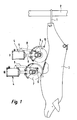
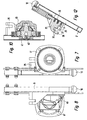
- FIG. 1 indicates at the hind legs by means of a hook 1 a slaughtered animal 3 suspended from a transport device 2, for example, a pig.
- a cutting tool generally designated 4
- a drive unit 5 u. a. containing one Electric motor
- a boom 6 a means of said Electric motor driven cutting blade 7 (for example a saw) and one by means of a piston / cylinder arrangement 8 between the two end positions I and II adjustable protective hood 9 has.
- the cutting tool is for attachment to a conventional multi-axis robot designed, to which the drive unit 5 is connected and can be screwed on.
- the boom 6 is by means Flange 6 'attached to the drive unit 5.
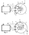
- FIG. 2 shows the guard 9 in the retracted position I according to FIG. 1;
- Figure 3 shows the protective hood 9 in full extended position II according to Figure 1, in which the Andschreib stresses 10 extends vertically downwards.
- FIG. 2 and 3 corresponds to the boom 6, a guide plate 15th screwed on, with the help of a Fixing block 16 (see also Figure 14).
- the Guide plate 15 has a recess formed as an incision Guideway 17, concentric with the axis of rotation 18th a circular rotary driven cutting tool 7 runs, but has a larger diameter than this.
- this guideway guide pins 19, 20 are guided, screwed to the protective hood 9 by means of screws 21 are.
- the guide plate 15 takes over the pins 19, 20 a part of the forces on the Cutting act on the guide body 10 and relieved thus the storage.
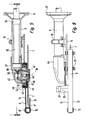
- the boom is the sixth at the same time housing a shaft 35 which in the boom. 6 is mounted by means of bearings 36, 37.
- the shaft 35 is from the electric motor provided in the drive unit 5 (not shown) driven.
- One at the end of the wave provided pinion 38 engages in a pinion 39, the on a drive pin 40 sits.
- On the drive pin 40th is by means of screw 41, the cutting blade 7 centric clamped.
- the boom 6 is in a housing 45 via, in in which the aforementioned components are arranged.
- the housing 45 has a ring 46th carries, the drive pin 40 with low radial Distance surrounds and on the means of screws 47 a annular cover plate 48 is screwed. Between the Cover plate 48 and a disc-shaped projection 49 of the Ring 46 is rotatable relative to these parts another ring 42, with the boom 6 facing Side plate 11 of the protective cover 9 by means of screws 12 is screwed.
- the bolted to the protective hood 9 Ring 42 thus rotates with the protective cover 9 in the between extension 49 and cover plate 48 formed groove 43rd
- the boom 6 facing away from side plate 13th extends so far to the axis of rotation 18 out that they outer circumference 7 'of the cutting blade 7 overlaps.
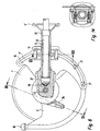
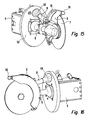
- Figures 15 and 16 show another Embodiment
- the embodiment according to Figures 1 - 14 is basically the same, but with the additional measure that between drive unit 5 and the cutting blade 7 bearing parts a Schmutzab utilizat plate 50 is arranged to the Drive unit to protect against contamination.
- This is provided with two openings. The one opening is in the Figures 15, 16 through the flange 6 'of the boom. 6 covered. Through this opening, the shaft 35 extends therethrough. Through the opening 51, the piston / cylinder arrangement extends 8 through. At this is a bellows 55 provided to prevent through the opening 51 Dirt passes through.
- the protective hood 9 extends over a sector of more as 90 °, in the exemplary embodiment about 135 ° to the to ensure described dirt repellency.
Landscapes
- Life Sciences & Earth Sciences (AREA)
- Engineering & Computer Science (AREA)
- Food Science & Technology (AREA)
- Processing Of Meat And Fish (AREA)
Abstract
Description
- Figur 1
- eine schematische Darstellung eines Ausführungsbeispiels an einem Schlachttier;
- Figur 2
- das Ausführungsbeispiel in Stellung I nach Figur 1;
- Figur 3
- das Ausführungsbeispiel in Stellung II nach Figur 1;
- Figur 4
- eine Seitenansicht (Rückansicht, wenn bezogen auf Fig. 1 - 3) des Ausführungsbeispiels;
- Figur 5
- eine Ansicht in Richtung der Pfeile Linie V-V in Figur 4;
- Figur 6
- eine Ansicht in Richtung der Pfeile VI-VI in Figur 5;
- Figur 7
- eine Ansicht in Richtung der Pfeile VII-VII in Figur 4;
- Figur 8
- ein Ansicht in Richtung der Pfeile VIII-VIII in Figur 4;
- Figur 9
- eine Ansicht in Richtung der Pfeile IX-IX in Figur 4;
- Figur 10
- eine Ansicht in Richtung der.Pfeile X-X in Figur 4;
- Figur 11
- eine Ansicht in Richtung der Pfeile XI-XI in Figur 4;
- Figur 12
- eine Ansicht in Richtung der Pfeile XII-XII in Figur 6;
- Figur 13
- eine Ansicht in Richtung der Pfeile XIII-XIII in Figur 4;
- Figur 14
- eine Ansicht entlang der Pfeile XIV-XIV in Figur 6;
- 15 und 16
- ein weiteres Ausführungsbeispiel in zwei unterschiedlichen perspektivischen Ansichten.
Claims (7)
- Schneidwerkzeug zum Aufschneiden eines Schlachttieres (3) mit einem kreisförmigen von einer Antriebseinheit (5) rotierend angetriebenen Schneidmesser (7) sowie einem in seiner Stellung gegenüber dem Schneidmesser veränderbaren Andrückkörper (10), und einer das Schneidmesser zumindest teilweise überdeckenden verstellbaren Schutzhaube (9), dadurch gekennzeichnet, dass der Antrieb des Schneidmessers (7) durch eine Welle (35) und Antriebsmittel (38, 39, 40) gebildet wird, die in einem an der Antriebseinheit (5) vorgesehenen Ausleger (6) angeordnet sind, und dass die Schutzhaube (9) an einer auf dem Ausleger (6) angeordneten Führungsplatte (15) um die Drehachse (18) des Schneidmessers (7) mittels einer an ihr angreifenden Kolbenstange (31) einer an der Antriebseinheit (5) angebrachten Kolben-/Zylinderanordnung (8) drehbar ist, und dass die den Antriebsmitteln (38, 39, 40) zugewandte Seitenplatte (11) der Schutzhaube (9) einen ersten Ring (42) aufweist, der gegenüber einem zweiten Ring (46), der an einem die Antriebsmittel (38, 39, 40) aufnehmenden Gehäuse (45) angeordnet ist, drehbar ist.
- Schneidwerkzeug nach Anspruch 1, dadurch gekennzeichnet, dass der erste Ring (42) in einer Nut (43) läuft, die an dem die Antriebsmittel (38, 39, 40) umschließenden zweiten Ring (46) gebildet ist.
- Schneidwerkzeug nach Anspruch 1 oder 2, dadurch gekennzeichnet, dass die Schutzhaube (9) zumindest mit ihrer den Antriebsmitteln (38, 39, 40) zugewandten Seitenplatte (11) mindestens einen Sektor von 90 - 150° des Schneidmessers (7), vorzugsweise ca. 135°, abdeckt.
- Vorrichtung nach einem der Ansprüche 1 - 3, dadurch gekennzeichnet, dass die Schutzhaube (9) in einer Führungsbahn (17) konzentrisch zur Drehachse (18) des Schneidwerkzeugs (17) gelagert ist, die in der Führungsplatte (15) vorgesehen ist.
- Vorrichtung nach einem der Ansprüche 1 - 4, dadurch gekennzeichnet, dass der Radius der Führungsbahn (17) größer als der des Schneidmessers (7) ist.
- Vorrichtung nach einem der Ansprüche 1 - 5, dadurch gekennzeichnet, dass der äußere Umfang der Schutzhaube (9) durch ein quadratisches Profil (9') gebildet wird.
- Vorrichtung nach einem der Ansprüche 1 - 6, dadurch gekennzeichnet, dass der Ausleger (6) und die Kolben-/Zylinderanordnung (8) zur Verstellung der Schutzhaube (9) sich durch eine Schmutzabweiseplatte (50) hindurcherstrecken und auf der der Schutzhaube (9) abgewandten Seite mit der Antriebseinheit (5) verbunden sind.
Applications Claiming Priority (2)
| Application Number | Priority Date | Filing Date | Title |
|---|---|---|---|
| DE102004022346 | 2004-04-28 | ||
| DE102004022346A DE102004022346B3 (de) | 2004-04-28 | 2004-04-28 | Schneidwerkzeug zum Aufschneiden von Schlachttieren |
Publications (2)
| Publication Number | Publication Date |
|---|---|
| EP1591014A2 true EP1591014A2 (de) | 2005-11-02 |
| EP1591014A3 EP1591014A3 (de) | 2006-01-04 |
Family
ID=34833261
Family Applications (1)
| Application Number | Title | Priority Date | Filing Date |
|---|---|---|---|
| EP05005926A Withdrawn EP1591014A3 (de) | 2004-04-28 | 2005-03-18 | Schneidwerkzeug zum Aufschneiden von Schlachttieren |
Country Status (2)
| Country | Link |
|---|---|
| EP (1) | EP1591014A3 (de) |
| DE (1) | DE102004022346B3 (de) |
Families Citing this family (7)
| Publication number | Priority date | Publication date | Assignee | Title |
|---|---|---|---|---|
| DE102006019632B3 (de) * | 2006-04-25 | 2007-12-13 | Banss Schlacht- und Fördertechnik GmbH | Verfahren zur Durchführung von zumindest einem Bearbeitungsschritt an einem Schlachttier sowie Bearbeitungsstation |
| DE202006007224U1 (de) * | 2006-04-28 | 2007-07-05 | Schmid & Wezel Gmbh & Co. | Antriebseinheit mit einem rotierenden Sägeblatt zum Anschluss an einen Roboter |
| FR2901666B1 (fr) * | 2006-06-01 | 2008-07-18 | Couedic Madore Equipement Soc | Procede et outil de decoupe de l'abdomen et du sternum d'un animal |
| DE102007021094B3 (de) * | 2007-05-03 | 2008-08-21 | Banss Schlacht- und Fördertechnik GmbH | Verfahren zum Bearbeiten eines Schlachttieres |
| FR2919473A1 (fr) * | 2007-08-01 | 2009-02-06 | Durand Internat Soc Par Action | Sciage de carcasses de porc ou analogue |
| DE102013104585B4 (de) * | 2013-05-03 | 2016-12-29 | Banss Schlacht- und Fördertechnik GmbH | Verfahren zur Durchführung von zumindest einem Bearbeitungsschritt an einem Schlachttier sowie Schneidwerkzeug |
| CN114800732A (zh) * | 2022-05-24 | 2022-07-29 | 安徽宏安木业有限公司 | 一种门套边框开槽设备及开槽方法 |
Citations (1)
| Publication number | Priority date | Publication date | Assignee | Title |
|---|---|---|---|---|
| EP0594791B1 (de) | 1991-07-18 | 2000-04-19 | Stork MPS B.V. | Verfahren und vorrichtung zum aufschneiden eines tierkörpers |
Family Cites Families (5)
| Publication number | Priority date | Publication date | Assignee | Title |
|---|---|---|---|---|
| IT1049042B (it) * | 1975-11-07 | 1981-01-20 | Pedrazzoli Spa | Involucro articolato per la protezione degli organi rotanti di una macchina utensile quale adesempio una troncatrice |
| US4153973A (en) * | 1976-01-26 | 1979-05-15 | Armour And Company | Tool for cutting materials and methods for sterilizing the same |
| US4848001A (en) * | 1988-03-14 | 1989-07-18 | Textron Inc. | Blade guard system for rotary saws |
| DE3943134B4 (de) * | 1989-12-28 | 2005-06-09 | Robert Bosch Gmbh | Klemmvorrichtung für ein an einer Führung verschiebbares Teil |
| US6220604B1 (en) * | 1998-05-27 | 2001-04-24 | George B. Champlin | Self-adjusting interlocking bushing |
-
2004
- 2004-04-28 DE DE102004022346A patent/DE102004022346B3/de not_active Expired - Fee Related
-
2005
- 2005-03-18 EP EP05005926A patent/EP1591014A3/de not_active Withdrawn
Patent Citations (1)
| Publication number | Priority date | Publication date | Assignee | Title |
|---|---|---|---|---|
| EP0594791B1 (de) | 1991-07-18 | 2000-04-19 | Stork MPS B.V. | Verfahren und vorrichtung zum aufschneiden eines tierkörpers |
Also Published As
| Publication number | Publication date |
|---|---|
| DE102004022346B3 (de) | 2005-09-08 |
| EP1591014A3 (de) | 2006-01-04 |
Similar Documents
| Publication | Publication Date | Title |
|---|---|---|
| EP0516642B1 (de) | Rollenschere | |
| DE102016218298B4 (de) | Greifvorrichtung | |
| EP3530348A2 (de) | Mischmaschine | |
| DE102005005340A1 (de) | Pneumatische Klemmvorrichtung | |
| EP1857223B1 (de) | Oszillationsantrieb mit einem Tiefenanschlag und Tiefenanschlag für einen Oszillationsantrieb | |
| DE102015113591A1 (de) | Vorrichtung zur Durchführung von Gehrungsschnitten | |
| EP1591014A2 (de) | Schneidwerkzeug zum Aufschneiden von Schlachttieren | |
| DE2318688A1 (de) | Anordnung bei einer vorrichtung zum transportieren und positionieren von gegenstaenden, insbesondere werkstuecken | |
| DE19855630A1 (de) | Parallele oder radiale, vorzugsweise pneumatisch betätigte Zange | |
| EP2012984A1 (de) | Antriebseinheit mit einem rotierenden sägeblatt zum anschluss an einen roboter | |
| DE102006010433B4 (de) | Holzbearbeitungsmaschine mit einem Schwenkrahmen | |
| DE102007014130A1 (de) | Handhabungsgerät | |
| DE102007008353B4 (de) | Rohrtrennvorrichtung | |
| DE1117440B (de) | Motorisch angetriebenes Handwerkzeug zum Entfleischen von Knochen | |
| DE20106956U1 (de) | Oberflächenbearbeitungsmaschine für Steine und harte Baustoffe | |
| EP1900896A2 (de) | Türband für einen selbstschliessenden Türflügel | |
| DE102005063016A1 (de) | Handwerkzeugmaschine mit Drehgriffverstelleinrichtung | |
| EP3366399A1 (de) | Elektrohandgerät | |
| DE69506677T2 (de) | Holzverarbeitungsvorrichtung mit Schlaghammer | |
| DE10351151B3 (de) | Maschine zum Bearbeiten von mit Schneidzähnen versehenen langgestreckten Werkstücken, insbesondere zum Schleifen von Bandsägeblättern | |
| DE667559C (de) | Handgetragene umlaufende Kreissaege o. dgl. mit biegsamem Wellenantrieb und einer gegen Verletzung schuetzenden Umkapselung | |
| DE1212342B (de) | Handgrasschere | |
| DE711056C (de) | Handschere zum Schneiden von hartem Stahldraht | |
| DE929928C (de) | Elektromotorisch angetriebene Holzbearbeitungsmaschine | |
| DE202010009543U1 (de) | Positionsvorgabeeinrichtung und damit ausgestattete Antriebsvorrichtung |
Legal Events
| Date | Code | Title | Description |
|---|---|---|---|
| PUAI | Public reference made under article 153(3) epc to a published international application that has entered the european phase |
Free format text: ORIGINAL CODE: 0009012 |
|
| AK | Designated contracting states |
Kind code of ref document: A2 Designated state(s): AT BE BG CH CY CZ DE DK EE ES FI FR GB GR HU IE IS IT LI LT LU MC NL PL PT RO SE SI SK TR |
|
| AX | Request for extension of the european patent |
Extension state: AL BA HR LV MK YU |
|
| PUAL | Search report despatched |
Free format text: ORIGINAL CODE: 0009013 |
|
| AK | Designated contracting states |
Kind code of ref document: A3 Designated state(s): AT BE BG CH CY CZ DE DK EE ES FI FR GB GR HU IE IS IT LI LT LU MC NL PL PT RO SE SI SK TR |
|
| AX | Request for extension of the european patent |
Extension state: AL BA HR LV MK YU |
|
| 17P | Request for examination filed |
Effective date: 20060317 |
|
| AKX | Designation fees paid |
Designated state(s): AT BE BG CH CY CZ DE DK EE ES FI FR GB GR HU IE IS IT LI LT LU MC NL PL PT RO SE SI SK TR |
|
| STAA | Information on the status of an ep patent application or granted ep patent |
Free format text: STATUS: THE APPLICATION IS DEEMED TO BE WITHDRAWN |
|
| 18D | Application deemed to be withdrawn |
Effective date: 20061003 |