EP1591182A2 - Trépan de forage, système de forage et procédé pour déterminer l'environnement électromagnétique d'un trépan de forage - Google Patents
Trépan de forage, système de forage et procédé pour déterminer l'environnement électromagnétique d'un trépan de forage Download PDFInfo
- Publication number
- EP1591182A2 EP1591182A2 EP05102946A EP05102946A EP1591182A2 EP 1591182 A2 EP1591182 A2 EP 1591182A2 EP 05102946 A EP05102946 A EP 05102946A EP 05102946 A EP05102946 A EP 05102946A EP 1591182 A2 EP1591182 A2 EP 1591182A2
- Authority
- EP
- European Patent Office
- Prior art keywords
- drill bit
- sensor
- coil
- sensor device
- drilling
- Prior art date
- Legal status (The legal status is an assumption and is not a legal conclusion. Google has not performed a legal analysis and makes no representation as to the accuracy of the status listed.)
- Withdrawn
Links
Images










Classifications
-
- B—PERFORMING OPERATIONS; TRANSPORTING
- B28—WORKING CEMENT, CLAY, OR STONE
- B28D—WORKING STONE OR STONE-LIKE MATERIALS
- B28D7/00—Accessories specially adapted for use with machines or devices of the preceding groups
- B28D7/005—Devices for the automatic drive or the program control of the machines
-
- B—PERFORMING OPERATIONS; TRANSPORTING
- B23—MACHINE TOOLS; METAL-WORKING NOT OTHERWISE PROVIDED FOR
- B23B—TURNING; BORING
- B23B51/00—Tools for drilling machines
- B23B51/04—Drills for trepanning
-
- B—PERFORMING OPERATIONS; TRANSPORTING
- B28—WORKING CEMENT, CLAY, OR STONE
- B28D—WORKING STONE OR STONE-LIKE MATERIALS
- B28D1/00—Working stone or stone-like materials, e.g. brick, concrete or glass, not provided for elsewhere; Machines, devices, tools therefor
- B28D1/02—Working stone or stone-like materials, e.g. brick, concrete or glass, not provided for elsewhere; Machines, devices, tools therefor by sawing
- B28D1/04—Working stone or stone-like materials, e.g. brick, concrete or glass, not provided for elsewhere; Machines, devices, tools therefor by sawing with circular or cylindrical saw-blades or saw-discs
- B28D1/041—Working stone or stone-like materials, e.g. brick, concrete or glass, not provided for elsewhere; Machines, devices, tools therefor by sawing with circular or cylindrical saw-blades or saw-discs with cylinder saws, e.g. trepanning; saw cylinders, e.g. having their cutting rim equipped with abrasive particles
-
- B—PERFORMING OPERATIONS; TRANSPORTING
- B23—MACHINE TOOLS; METAL-WORKING NOT OTHERWISE PROVIDED FOR
- B23B—TURNING; BORING
- B23B2226/00—Materials of tools or workpieces not comprising a metal
- B23B2226/75—Stone, rock or concrete
-
- B—PERFORMING OPERATIONS; TRANSPORTING
- B23—MACHINE TOOLS; METAL-WORKING NOT OTHERWISE PROVIDED FOR
- B23B—TURNING; BORING
- B23B2251/00—Details of tools for drilling machines
- B23B2251/50—Drilling tools comprising cutting inserts
-
- B—PERFORMING OPERATIONS; TRANSPORTING
- B23—MACHINE TOOLS; METAL-WORKING NOT OTHERWISE PROVIDED FOR
- B23B—TURNING; BORING
- B23B2260/00—Details of constructional elements
- B23B2260/10—Magnets
-
- B—PERFORMING OPERATIONS; TRANSPORTING
- B23—MACHINE TOOLS; METAL-WORKING NOT OTHERWISE PROVIDED FOR
- B23B—TURNING; BORING
- B23B2260/00—Details of constructional elements
- B23B2260/128—Sensors
-
- B—PERFORMING OPERATIONS; TRANSPORTING
- B23—MACHINE TOOLS; METAL-WORKING NOT OTHERWISE PROVIDED FOR
- B23B—TURNING; BORING
- B23B2270/00—Details of turning, boring or drilling machines, processes or tools not otherwise provided for
- B23B2270/38—Using magnetic fields
-
- B—PERFORMING OPERATIONS; TRANSPORTING
- B23—MACHINE TOOLS; METAL-WORKING NOT OTHERWISE PROVIDED FOR
- B23B—TURNING; BORING
- B23B2270/00—Details of turning, boring or drilling machines, processes or tools not otherwise provided for
- B23B2270/48—Measuring or detecting
Definitions
- the invention relates to a method for determining the electromagnetic Environment of a drill bit, in particular for the detection of reinforcements, and a corresponding drilling system and a drill bit when they are used Quickly detect reinforcing iron using the procedure.
- a drilling system in which a Metal detector and / or a voltage tester are attached to a boom, which in turn can be aligned with a drill in the direction of the borehole can be fixed.
- the purpose of the metal detector is to drill into To avoid water pipes or live line by the body, at which is to be drilled, is first checked by means of the metal detector.
- the Voltage tester allows a user to determine if wires are on the drilling site are under tension.
- this known drilling system does not allow determination of the electromagnetic environment of a drill bit, resulting in a borehole located.
- DE 40 27 020 C2 teaches a method and describes a device for Determination of the presence of metallic reinforcement elements in the Interior of a concrete component. It is an elongated electromagnetic probe provided, which can be inserted into a previously drilled hole to To provide information on the depth of any reinforcement elements. To this Way, it is possible to undercut holes at a sufficient distance from any reinforcing elements.
- the disadvantage is that holes on conventionally must be pre-drilled, and that measurements inside of the drilling part can thus be carried out only after drilling.
- DE 39 16 856 A1 discloses a device for finding and protecting against the drilling of laid in concrete or the like metal parts, in the a low power circuit is closed when the drill syringe on a Clamping sleeve, a tension wire or the like hits. Will the circuit closed, so the drill via switch contacts in the Power automatically shut down. It is assumed that the laid metal parts are at least partially accessible and on a Pole of the circuit can be connected. This device offers thus no possibility, for example, reinforcements that are completely in the concrete are embedded, detect and prevent iron hits.
- DE 101 29 597 C1 describes a tool for machine tools, in which the Shape and / or the dimension of marks in the cutting surface Indicates the degree of wear.
- This can be a Wear level detected with a sensor and in a control unit to a Signal are processed, for example, an optical, acoustic and / or electrical signal through which a tool driving the tool can be turned off. As a result, only the tool, but not the Protected or monitored piece to be processed.
- DE 196 34 533 A1 describes a method and a device for Determination of physical and chemical parameters in mineral solid media, in which or a measuring solution while drilling through the Drilled hole and then examined.
- the measuring solution can by means of electrochemical sensors are investigated for flow analysis, the For example, in the measuring solution leading hose lines at the output a Bohrfußes can be attached.
- the described structure is complex and allows an investigation of only a few wells per Hour, especially if physical and chemical parameters of the medium also be determined depending on the drilling depth.
- EP 1 092 988 and EP 1 092 989 describe an inductive sensor head for Metal detectors or an inductive sensor arrangement and a method for Detecting iron-containing objects that turn into a lightweight tool For example, in an electrically operated hammer drill, integrate.
- the invention is the The object of the invention is to provide a device and a method with which in a simple way physical parameters of a particular means a drill with diamond crown to be degraded medium or their change let determine.
- embedded in concrete ferromagnetic Reinforcements can be detected in time to so-called "iron hit", i. one Boring a reinforcement, to prevent.
- the above object is achieved by a drill bit, a Drilling system and a method in which a determination of the electromagnetic environment of a drill bit or a determination of Change sizes of this environment takes place.
- Also according to the invention is a drill bit with a sensor device whose physical parameter (s) are determined by the electromagnetic environment of Drill bit depends on or hang.
- the term "electromagnetic environment” all parameters relating to electricity and / or magnetism, i.e. electrical, magnetic, electrochemical, electromagnetic, etc. Parameters of the environment. Basically, there is no restriction regarding the Type of drill bit influenced by the electromagnetic environment physical characteristic (s) of the sensor device provided. It is preferred However, a sensor device selected, the optical or electrical Properties (or changes of these characteristics) Conclusions on the allow instantaneous state of the electromagnetic environment, since optical and electrical properties in an optionally editable signal to convert easily for evaluation.
- the term "drill bit environment" is preferably that of the drill bit directly or indirectly to neighboring materials, which are in a radius of the drill bit whose radius (approximately) the Drill radius of the drill bit corresponds.
- the radius of the detected circumference between 0.1 to 1 times the radius of the drill bit or between a simple and a triple value of the radius of the drill bit lie.
- a small radius leads to a high sensitivity while a by definition covers a large area, for example in the Case of an impending "iron hit" a correspondingly large advance warning time allows.
- a detection of an asymmetric Environment possible.
- the suitable configurations of the sensor device and / or a connected to the sensor device measuring and / or Evaluating takes the specialist in the field of Sensor devices, measuring and evaluation circuits relevant literature.
- the invention provides an "intelligent" drill bit which For example, a suitable, connected to the sensor device measuring and Evaluation circuit enabled a user just before drilling a reinforcing iron or directly when drilling a reinforcing iron to give the appropriate signal. Also, a corresponding signal of the Sensor device or connected to the sensor device circuit a control unit are supplied directly or indirectly, which Bohrparameter such as speed, torque, additional kinematics, etc. to current drilling conditions adapts.
- the invention provides a drilling system with a Sensor device having drill bit and with a corresponding, with the sensor device connected measuring and evaluation circuit, wherein the Sensor device and the measurement and evaluation circuit selected and are configured that the ferromagnetic properties and / or the Conductivity of a reinforcing iron can be detected as measured variables.
- detecting these variables is that they are largely regardless of, for example, water-related moisture, from the temperature and are from the dirt.
- a great advantage of a magnetic, i. one Inductive, measuring method is that a reinforcing iron contactless and therefore in can be detected in advance. This is also measurement based on the Eddy current effect of the case. Since the signal of an eddy current sensor both from the permeability ⁇ as well as the conductivity ⁇ of the to be detected Material depends, for example, even with this measurement method Whether it is iron or metal in a detected metal Non-ferrous metals trades.
- the sensor device contains at least one magnetic field sensor, in particular a semiconductor magnetic field sensor.
- Ferromagnetic reinforcement element can be particularly well by a Detect magnetic field sensor whose output depends on the size of the Sensor running magnetic flux or changes of the by the Sensor dependent magnetic flux depends.
- Detect magnetic field sensor whose output depends on the size of the Sensor running magnetic flux or changes of the by the Sensor dependent magnetic flux depends.
- fluxgate arrangements can be used as a magnetic field sensor become.
- one or a plurality of magnetic field sensors will be nearby the cutting or dismantling elements so close to the place of degradation appropriate.
- semiconductor magnetic field sensor can be as Making miniature components, resulting in a mounting near the Dismantling elements facilitated. Belong to the family of semiconductor magnetic field sensors Hall elements, magnetoresistive (MR) sensors and Giant Magnetoresistive (GMR) sensors. Hall elements respond to a change in the magnetic Flux density at the location of the sensor with a current or voltage change, which can be evaluated. Magnetoresistive sensors and GMR sensors react with a resistance change.
- Hall sensors are cheaper, more reliable, and easier to use today to integrate a drill bit as coils. Their sensitivity, however, is less, also permanent magnets or a field exciter needed to To detect reinforcing bars.
- the semiconductor magnetic field sensors are each on one of preferred direction of rotation of the drill bit opposite side of each Removal element arranged.
- the Semiconductor magnetic field sensors during a destructive rotation of the drill bit in the preferred direction of rotation so to speak "in the shadow" of the respective Degrading element, causing the semiconductor magnetic field sensors from damage during the drilling process.
- the drill bit with a permanent magnet or a Electromagnet be provided whose magnetic field from the electromagnetic Affected environment of the drill bit and is detected by the sensor device.
- a permanent magnet or an electromagnet can be a generate static magnetic field or an alternating magnetic field, which for example, in the presence of a ferromagnetic reinforcing iron is changed, and a measurable change of the magnetic flux or magnetic flux density at the location of the sensor device causes.
- the Using an alternating magnetic field to "scan" the The electromagnetic environment of the drill bit is particularly advantageous because of the caused by the alternating field influencing the electromagnetic environment the drill bit, which can be detected by the sensor device, also temporally changed and with appropriate filtering over the Sensor device, for example, from “natural” can be distinguished occurring electromagnetic interference. This allows an increase in detection sensitivity.
- a static magnetic field can be naturally occurring electromagnetic Disturbance disturbances "and thus also an increase in the Enable detection sensitivity.
- the sensor device includes at least one coil. This can serve both as a detection element and as a signaling element.
- a detection element changes in the electromagnetic environment of the coil caused changes in the Inductance or impedance of the coil as a parameter for determining the electromagnetic environment of the drill bit serve.
- Signaling element may be the coil for generating a static Magnetic field or an alternating magnetic field can be used, as above described.
- a coil can also be used to generate eddy currents whose expression of the electromagnetic nature of the materials surrounding the coil depends. Consequently, by appropriate design or evaluation of the Coil driving signal and by appropriate evaluation of the over Coil outflowing eddy current losses information about the electromagnetic The nature of the materials surrounding the coil are determined. hereby can the electromagnetic nature of non-ferromagnetic Determine materials around a drill bit.
- a bifunctionality of the coil, in which they both as a detection element as well acts as a signaling element is in the circuitry Realization consuming, but allows a particularly simple realization of a active signal generator and the detection element.
- the sensor device comprises at least one around the Rotation axis of the drill bit wound coil, in or on the drill bit is arranged.
- the coil has at least one turn and is preferably located near the depleting elements of the crown. "In the Proximity "means here in the same” foremost "half, third, quarter, fifth or Sixth of the crown in which the degrading elements are located.
- the drill bit itself may be partial, primary or complete ferromagnetic material, in particular of iron or iron alloy, exist, so that a path of low magnetic resistance from the coil up realized to the degrading elements and vice versa.
- the drill bit When the drill bit approaches a ferromagnetic material, it changes Inductance or impedance of the coil. With various known methods can be the inductance or impedance of the coil or measure their change and evaluate, for example by detuning an electric Resonant circuit or by changing the adjustment of a bridge circuit.
- the coil can provide information about the electromagnetic environment of Deliver drill bit.
- the sensor device comprises at least one exciter coil, in particular at least one wound around the axis of rotation of the drill bit Exciter coil, and at least one sensor coil, in particular at least one sensor coil wound parallel to the outer surface of the drill bit, in or on the drill bit are arranged.
- the drill bit is preferred made of non-ferromagnetic and / or poorly conductive material, in particular made of non-ferromagnetic steel.
- the exciter coil (s) and the Sensor coil (s) are preferably orthogonal to each other.
- penetration depth Engl: skin depth
- Materials in which there is a penetration depth, for example, at 10 kHz, which is greater than the usual wall thickness of a drill bit.
- Material Conductivity ⁇ (10 6 S / m) Conductivity relative to copper Penetration depth at 10 kHz in ⁇ m 304 ss 1.3 0022 4400 titanium alloy 00:59 0010 6600
- the material of the drill bit has a resistivity of> 8 ⁇ 10 -7 ⁇ m. The higher the better.
- Is an alternating magnetic field by, for example, the Axis of rotation of the drill bit extending exciter coil, e.g. the above described, is constructed in one or more example small and attached to the edge of the drill core sensor coils a voltage induced. This is the greater, the greater the coupling between the sensor and the exciter coil is. Is there a reinforcement close to the Sensor coil, so this bundles the magnetic field lines and the coupling between excitation and sensor coil changes, which according to the invention can be measured and evaluated.
- the excitation and sensor coils are preferably orthogonal arranged to each other.
- the drill bit in the case of this kind of detection at least substantially made of non-ferromagnetic material, to a coupling of the exciter and sensor coils through the drill bit itself suppress.
- the drill bit should at least in be made essentially of poorly conductive material.
- the Expression "essentially” indicates that the main body of the drill bit off
- the preferred material should be made while items such as erosive Elements, parts of the sensor device, signal lines, any Fasteners for connecting the drill bit to a drive machine, etc. can be made of a non-preferred material.
- the sensor device comprises at least one capacitive electrode.
- capacitive electrodes may be mounted in pairs proximate a deboning element of the drill bit. Changes in the electromagnetic environment of the drill bit cause changes between the capacitive electrodes. For example, the presence of a reinforcing bar near the drill bit can cause a change in the capacitance between the electrodes, since the relative constants of electricity are: ⁇ concrete ⁇ 6 and ⁇ iron ⁇ ⁇ , respectively. Also, the drill bit itself can act as a capacitive electrode. If, for example, the drill bit touches a reinforcing iron, the capacity of the electrical system comprising the drill bit as a capacitive electrode increases.
- Such changes in the capacity can be determined by means of known measuring methods and For example, according to the charge transfer principle, by a Measure oscillator circuit or a bridge circuit.
- the sensor device comprises at least two electrically conductive Areas that are electrically isolated from each other. These are preferably in a removing or degrading area of the drill bit arranged.
- a drill bit designed in this way touches a reinforcing iron, then may be two or more of the electrically conductive regions through the Reinforced iron itself shorted.
- the electrically conductive regions may be in an abrasive region of the Drill be integrated or even formed by the drill bit itself.
- an electrically conductive drill bit itself can serve as a contact so that only one of the drill bit electrically isolated electrical connection to a corresponding measuring and / or evaluation unit must be returned.
- a sensor device based on electrically conductive regions the for example, a resistance measurement and / or as an ohmic contact switch serve, has the disadvantage that they only detect a reinforcing rod, if this is already touched.
- this disadvantage has the advantages of low production costs and a simple transmitter counter.
- the Contact elements do not even have to be preloaded with a spring, but can also, as mentioned above, wear contacts, which by the Drilling process itself be abraded.
- the electrically conductive regions are so in erosive Area arranged so that they are also at a wear of the erosive area stay electrically isolated from each other.
- Such an arrangement of the electrically conductive regions ensures that their Functionality is maintained, even when partially during the drilling process to be worn out. Also, such an arrangement to protect a serve the measuring circuit connected to the electrically conductive areas, i. especially protect against short circuits in a measuring circuit.
- the sensor device comprises at least two electrically conductive Elements that are electrically separated from each other at the level of the erosive elements are mounted resiliently or movably.
- the drill bit comprises a communication device which Sensor signals from the sensor device directly or indirectly receives, and these in converts serial signals that can be communicated via a single signal line are.
- one or more sensor signals are the Sensor device tapped and a measuring and / or evaluation device fed, for cost reasons separately from the drill bit, in particular in a prime mover is running. Will not be countermeasures If there is a need for a rotary transmission path for each of the tapped sensor signals. Rotatory signal transmission paths are not only noise sources, but also often expensive, in need of maintenance and unreliable. In addition, for example, in a tool holder, where such Rotatory interfaces are preferably provided, only limited space for such devices.
- a serial communication device for example, as an interface between the sensor device and a corresponding measuring device or as an interface between a with the Sensor device directly connected measuring device and a corresponding Evaluation device functions.
- the drill bit on a measuring device the sensor signals of the sensor device receives directly or indirectly, and this in measuring signals transforms.
- the conversion of the sensor signals into measurement signals comprises preferably a gain and / or a Meß vigilantnwandwandlung.
- drilling crown side conversion of the sensor signals can be a Falsification of the sensor signals are suppressed on the transmission path.
- a drill bit side serial Communication device for transmitting the measurement signals provides a Bohrkronen worne arrangement of the measuring device advantages in the Unadulteratedness of the measurement results.
- the drill bit preferably has a Power supply device based solely on the rotational movement the drill bit, for example relative to one in the prime mover arranged permanent magnets or electromagnets, energy gains, the to power one or more of these devices. Also This eliminates the need for a rotary electrical connection avoided.
- Corresponding power supply device in particular inductively coupled, current-directing and energy-storing Circuit arrangements are known to the person skilled in the art and do not require any here Explanation. Accordingly, the relevant literature on non-contact Power referenced.
- the above communication, measuring and / or Power supply devices can be used as an integrated semiconductor device for example, in one piece construction, extremely cost effective, i. at a price which hardly affects the costs of a drill bit. Nevertheless, could These devices can be realized, for example, as a module which is such in the Drill bit is arranged, i. at corresponding contacts of the drill bit is fixed, that it with usual tool from a "brewed” Remove drill bit and insert into a new drill bit.
- sensor devices designed as degrading elements are Preferably carried out so that they after "consumption" with conventional tool of removed the drill bit and used in their place new sensor devices can be. Accordingly, corresponding contact devices can both on the sensor devices designed as degrading elements as well as on Main crown part of the drill bit to be provided.
- the invention provides that a drill bit according to the above Embodiments in a drilling system use finds that a measuring and / or Evaluation circuit or device comprising the state of Sensor device measures or evaluates such that ferromagnetic material in detected near the drill bit and issued a corresponding signal can be.
- the measuring or evaluation device both integral with as also be implemented separately from the drill bit.
- the Measuring or evaluation device wholly or substantially separately from the Running away worn drill bit.
- An embodiment of the measuring or evaluation device entirely or im Essentially separate from the drill bit allows system modularity
- the system costs are thereby lowered that dispensed with a measuring device in the drill bit itself can.
- cost-cutting is when, for example, in the housing of the Drive machine of the drilling system arranged measuring device designed in such a way is that ensures compatibility with various sensor devices is. This allows replacement of the drill bit without a corresponding Force replacement of the measuring device.
- the possibility of the drill bit the To adjust drilling conditions through exchange extends the Functionality of the drilling system. If the measuring device is wholly or in the essentially separate from the drill bit to be classified as consumable executed, so there are fewer disadvantages when the measuring device high quality and / or versatile, which is the system performance improved.
- Detecting a ferromagnetic material near a Sensor device is for example from the field of metal detectors known. Depending on the embodiment of the sensor device are different known measuring and evaluation methods and circuits available. Accordingly, with respect to the implementation of a measuring and / or Evaluation circuit pointed to the relevant literature.
- the output from the evaluation device signal have both informative and instructive character.
- the signal serve to inform a user of the drilling system that a reinforcement or other metallic object in the vicinity of Drill bit is located. It could also be signaled that a reinforcement was drilled that the drill bit for the currently degraded material unsuitable is that a power or water pipe near the Bohrkrone is located, or that a sudden increase in the degree of moisture the bottom of the hole has occurred.
- the signal could serve to the user to recommend an adaptation of the drilling parameters to the drilling conditions or to automatically initiate such an adjustment. For example, that could Drilling system the torque, the cutting speed, the water supply, the Contact pressure, the drilling power, etc. by means of the evaluation device automatically adjust the output signal to the drilling conditions.
- the invention comprises a drilling system with a drill bit according to one of the above statements, wherein the Sensor device comprises at least one coil, an exciter circuit, the excited at least one coil such that eddy currents in which the coil surrounding material occur; and a measuring and evaluation device, the Eddy current losses of the coil so measures and evaluates that the condition of the material adjacent to the coil is determined and a corresponding signal can be issued.
- the Sensor device comprises at least one coil, an exciter circuit, the excited at least one coil such that eddy currents in which the coil surrounding material occur; and a measuring and evaluation device, the Eddy current losses of the coil so measures and evaluates that the condition of the material adjacent to the coil is determined and a corresponding signal can be issued.
- An evaluation of the eddy current losses occurring over the drill bit is especially advantageous because u. a. also detecting non-ferromagnetic Materials near the drill bit is possible.
- the invention relates to a drilling system, in the drill bit with a potential to earth applied and a Leakage current is measured, the over the drill bit and the bottom of the hole (mass) flows.
- the electrical resistance changes between the defined potential of the drill bit, for example a diamond device, and mass.
- the electrical resistance can be measured by measuring the leakage currents through the drill bit to earth. Direct ohmic contact with the reinforcing bar increases the effective conductive area of contact between the bit and the ground as the surface of the entire network of reinforcement is added to the drill bit surface. It is advantageous if the main body of the drill bit itself is electrically isolated, and only the degrading elements of the drill bit are electrically conductive and contacted with a corresponding sensor device, measuring device and / or evaluation device.
- the invention relates to a drilling system in which the drill bit is subjected to an alternating voltage or alternating current and the power radiated by the drill bit is measured.
- the drill bit is an electric AC or AC impressed, whose or its frequency preferably in the kHz to MHz range. Meets the drill bit on Reinforcing iron, so the reinforcement acts as an antenna, and the radiated Performance of the system increases.
- This change in radiated power can measured and evaluated according to the above.
- the drilling system preferably comprises a measuring and Evaluation device, the measured leakage current or the measured Abstrahlaku measured and evaluated so that ferromagnetic material in be recognized near the drill bit and a corresponding signal generated can.
- the drilling system comprises a signaling device incorporated in Depending on the signal an adaptation of one or more Drilling parameters automatically makes, and / or a user an adjustment one or more Bohrparameter perceptible signals, and / or a Users perceive the detection of a target, in particular visually and angled, signaled, and / or a user exchange the drill bit perceptibly signaled, and / or automatically stops the drilling process.
- the adaptation of one or more drilling parameters comprises one Adjustment of the torque, the cutting speed, the water supply, the Contact pressure and / or drilling performance.
- a evaluation according to the invention comprise a corresponding measurement, and vice versa, as well as a detection according to the invention both a measurement and may include an evaluation.
- the signal path from the sensor device via a possible measuring device and a possible evaluation device is preferably divided into two parts namely an analog part and a digital part. It can a task of the analog part, the signals of the sensor device in a for example, for the evaluation device or a control device of the Drilling system to bring favorable shape. This can take the form of a analog amplification, transmission (e.g., by inductive or capacitive Coupling) and / or filtering.
- An analog-to-digital conversion in a known manner For example, analog voltages can be converted to digital by means of an A / D converter Voltages or analog frequency components in "digital" voltage pulses given frequency are converted.
- the digital part includes a digital signal evaluation for example medium software, whose task it can be detected from the detected, possibly with errors and noise Affected measuring signals with high probability to deduce whether actually a rebar is located in front of the drill bit.
- a digital signal evaluation for example medium software, whose task it can be detected from the detected, possibly with errors and noise Affected measuring signals with high probability to deduce whether actually a rebar is located in front of the drill bit.
- digital part of a decision-making process in terms of measures that for example, be taken after detection of a reinforcing iron should (display, shut down engine, ).
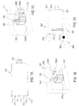
- FIG. 1A shows a first embodiment of a drill bit according to the invention 110 with a main crown part 111, a degrading region 112, a plurality degrading members 113 and a fixing member 114 and a plurality Semiconductor magnetic field sensors 112 as a sensor device according to the invention, the are arranged in the degrading region 112.
- the state of each Semiconductor magnetic field sensors 121 depends on the electromagnetic environment of Drill bit 110 from.
- About the attachment part 114 can be the drill bit 110th for example, couple with the drive shaft of a prime mover.
- the degrading elements 113 may be integral with the main crown part 111 executed, or be implemented as separate units by means of a corresponding fastening method or corresponding fixing elements solvable or non-releasably attached to the main crown portion 111.
- the semiconductor magnetic field sensors 121 for example, Hall elements, magnetoresistive sensors and giant magnetoresistive (GMR) Sensors are used.
- the semiconductor magnetic field sensors 121 each in one of the preferred direction of rotation of the drill bit 110th arranged opposite side of a respective degrading element 113, are thus during a degrading rotation of the drill bit 110 in preferred direction of rotation, so to speak "in the shadow" of the respective degrading Elements 113 and so are damaged during the drilling process protected.
- the semiconductor magnetic field sensors 121 in the degrading Area 112 of the drill bit 110 can in particular the electromagnetic Environment of the drill bit 110, which is in the immediate vicinity of the degrading Area 112 of the drill bit 110 is located, examined or evaluated.
- Figures 1B and 1C show respective schematic detail views of a possible Arrangement of a Hall sensor 121H with two permanent magnets 128S, 128N, for example, as semiconductor magnetic field sensors 121 in a drill bit according to Figure 1A could find application.
- the Hall sensor 121H and the two Permanent magnets 128S, 128N are in a plastic sheath, for example in a potting compound 130, or in a non-ferromagnetic metal in order Forming embedded.
- the two permanent magnets 128S, 128N are arranged so that their respective magnetic main axis perpendicular to a wear surface 131 provided side of the formed by the potting compound 130 Semiconductor magnetic field sensor 121 are aligned.
- the two permanent magnets 128 S, 128 N arranged so that their respective magnetic main axis are aligned parallel to the wear surface.
- FIG 2A shows a further embodiment of the invention, wherein a Drill bit 210 analogous to the drill bit 110 shown in Figure 1 a Main crown part 211, a fixing part 214 and a degrading area 212 having a plurality of degrading elements 213.
- the drill bit 210 is equipped with a coil 222, the acts as a sensor device according to the invention.
- the coil 222 is preferably connected to a detector circuit which in accordance with the known principle of a metal detector, the coil 222 excited and measures and evaluates their impedance changes.
- the drill bit 210 approaches a reinforcing rod 281, so the course and the strength changes through the energized coil 222 induces magnetic field 282, which in turn causes a change in the magnetic field Impedance of the coil 222 causes.
- the proximity of a Find reinforcing iron to drill bit 210 is preferably connected to a detector circuit which in accordance with the known principle of a metal detector, the coil 222 excited and measures and evaluates their impedance changes.
- the drill bit 210 approaches a reinforcing rod 281, so the course and the strength changes through the energized coil 222 induces magnetic field 282, which in turn causes a change in the magnetic field Impedance of the coil 222 causes.
- the proximity of a Find reinforcing iron to drill bit 210 is preferably connected to a detector circuit which in accordance with the known principle of
- Figures 2B and 2C show respective embodiments of an inductive element that may be used in a drill bit as a sensor device. Shown is a U-shaped yoke 224 having two yoke legs and a connecting yoke leg connecting piece.
- the yoke is made of a material of high permeability, in particular of a ferromagnetic metal, and has at its open end its U-shape an air gap which is narrower than the distance between the yoke legs.
- a coil 222 ' is wound around the yoke 224, preferably around the connector, to realize a high quality coil 222'.
- FIG. 2C dismantling elements 213 'are arranged next to the air gap at the respective yoke leg end.
- a high permeability article such as a reinforcing bar near the deoxidizing elements 213 'effectively causes an easily detectable, magnetic short circuit of the coil 222' via the yoke 224 extended by the depleting elements 213 '.
- Figure 2D shows an embodiment of a drill bit 210 'with a sensor device in the form of a yoke-coil combination formed according to the embodiment of Figure 2C.
- About the slip rings 243 can be a circuit between the at the rotating drill bit 210 'mounted coil 222' and a quasi-stationary Establish measuring device.
- FIG. 2E shows a modification of FIG Embodiment of Figure 2D, in which the slip rings 243 'of a Tool holder 274 a suitable for driving a drill bit Drive machine are included.
- An ohmic signal path between Winding ends of the coil 222 'and the respective slip rings 243' can over in or on the drill bit 210 'arranged lines 240 and over in or on the tool holder arranged lines 240 'are produced.
- a cost-effective separable ohmic connection of the lines 240 'of Tool holder with respective drill bit conduits 240 may, as shown, for example, via respective, with appropriate conductive and insulating Areas executed pins 246 on the attachment portion 214 'of the drill bit 210' take place, contact the respective contact surfaces 245 of the tool holder.
- pins 246 for transmitting power from the tool holder 274 to the drill bit contribute.
- FIG 3A shows a further embodiment of the invention, in which a Drill bit 310 analogous to the drill bit 110 shown in Figure 1 a Main crown part 311, a degrading area 312, several dismantling Having elements 313 and a fixing part 314.
- the drill bit 310 both with an excitation coil 322E and with several in the depleting region 312 of the bit 310 arranged sensor coils 322S equipped, the latter as act according to the invention sensor device.
- the excitation coil 322E induces Magnetic field, the shape and strength of the impedance of the sensor coils 322S which provides information about the electromagnetic environment of the drill bit 310 can deliver. Due to the illustrated arrangement of the sensor coils 322S in degrading region 312 of the drill bit 310 may in particular the electromagnetic environment of the drill bit 310, which is in close proximity of the degrading region 312 of the drill bit 310 is examined or be evaluated.
- FIG. 3B shows an exemplary embodiment of an inductive element that can be used as both Magnetic field exciter as well as a magnetic field sensor in the sense of a can act according to the invention sensor device.
- the inductive element shown comprises a U-shaped yoke 324, the two Yoke leg and a connecting piece connecting the yoke legs having.
- the yoke legs are each as a permanent magnet 328th made of different polarity, so that the yoke 324 is a uniform build up magnetic field.
- the yoke is made of a material of high permeability, in particular made of a ferromagnetic metal.
- the yoke legs however, sections of the yoke legs may be of a rare earth be manufactured, which has pronounced permanent magnetic properties.
- a sensor coil 322S ' is wrapped around the yoke 224, preferably around the yoke 224 Connector, wound.
- the yoke has its U-shape at the open end Air gap, which is narrower than the distance between the yoke legs, what together with the high permeability of the yoke material to a sensor coil 322S 'high quality leads.
- the pole pieces may themselves carry the cutting segments, i. the dismantling elements of the drill bit form, and would then preferably out appropriate materials such as Ni matrix or industrial diamonds to manufacture.
- the degrading elements 313 ' are preferably made of a material higher Permeability, in particular made of a ferromagnetic metal. On this meadow causes a high permeability object such as a Reinforcing bar near the deboning elements 313 'effectively a light detectable, magnetic short circuit of the sensor coil 322S 'via the yoke 324 extended by the degrading elements 313 '.
- the inductive element of Figure 3B can be analogous to the embodiments FIGS. 2D and 2E as part of a drill bit according to the invention.
- the rotation of the drill bit during drilling is in the yoke 324th formed magnetic circuit formed by the two permanent magnets 328th is biased, each time induces a voltage when the air gap of the Yoke on a ferromagnetic article, e.g. on a rebar, moved past.
- the reinforcing iron reduces the effective air gap of the magnetic circuit of the yoke, resulting in a flux change and thus after the Induction law leads to an induced voltage. Because the Cutting speed is always about the same, the induced voltage is over different Bohrkronendruchmesser comparable.
- FIG. 3C shows a further embodiment of an inventive device Drill bit 310 'with a wound around the axis of rotation of the drill bit 310' Exciting coil 322E 'and several parallel to the lateral surface of the Main crown part 311 'of the drill bit 310' wound sensor coils 322S ", which in or are arranged on the drill bit so that the excitation coil 322E 'and the Sensor coils 322S "are orthogonal to each other.
- the drill bit is preferably made of non-ferromagnetic and / or poorly conductive material, in particular from non-ferromagnetic steel, manufactured to eliminate eddy current effects curb preferred AC-based measurement method. To this still in addition to reducing the drill bit can be slotted at a suitable location become.
- the 322S "sensor coils can be used in conventional multi-layer circuit board technology on flexible, organic substrates (e.g., polyamide) be made so that they simply as a total band on the drill bit 310 ' can be glued on.
- the connection of the coils 322 to a measuring and Evaluation electronics can then also with a ribbon cable, the corresponding lines 340, and via a coupler or slip rings 343 be realized.
- a sense amplifier in the Bohrkrone be 310 'integrated for example by means of a serial Protocol communicates with a corresponding evaluation device, e.g. is housed in a prime mover.
- the drill bit 310 'shown in FIG. 3C is particularly suitable for measuring methods.
- the excitation coil 322E 'applied axially to the drill bit 310' generates an alternating magnetic field, for example in the kHz frequency range and the distortion of this field, for example, due to the proximity of a Arm michsseisens the coils 322 can be caused by means of parallel to the lateral surface of the drill bit applied sensor coils 322S "is detected.
- Figure 4A shows details of a drilling system according to another Embodiment of the invention.
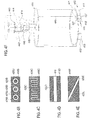
- the degrading element 413 for example, a conductive matrix 416 with Diamond grains, pass a plurality of electrically conductive regions 425, which through a respective electrically insulating region 426 of the electrically conductive Material of the element 13 are electrically isolated.
- An electrically conductive area 425 is via a first line 440 with a measuring and evaluation device 450th connected.
- the element 413 is via a second electrical line 440 'connected to the measuring and evaluation device 50.
- FIG. 4A shows by way of example only the connection of one of the electric conductive areas 425 with the measuring and evaluation 450 represents would be typically all electrically conductive areas 425 each individually or in groups in series or parallel connection with appropriate input or Output gates of the measuring and evaluation 450 connected.
- the measuring and evaluation device 450 By means of resistance measurement via the electrically conductive regions 425 and the electrically conductive element 413, the measuring and evaluation device 450, the preferably via a signal processing and a corresponding display provides information about the electromagnetic environment of the drill bit.
- FIGS 4B to 4E show various possible embodiments of a degrading element, in particular a degrading element for use in a drilling system analogous to the embodiment of Figure 4A. Shown is each a cross-section of a preferably annular and one-piece executed degrading element parallel to a degradation or abrasion level this element, which is typically perpendicular to the axis of rotation of the drill bit arises.
- this element which is typically perpendicular to the axis of rotation of the drill bit arises.
- the electrically conductive regions and / or the electrically conductive Elements also with a wear of the eroding area of the drill bit stay electrically isolated from each other.
- Figure 4B shows a degrading element of a drill bit according to another Embodiment of the invention, wherein the electrically conductive regions 425B Similar to the embodiment shown in Figure 4A circular cylindrical formed and of respective annular cylindrical electrically insulating Are surrounded areas 426B.
- the electrically conductive regions 425B and the electrically insulating regions 426B pass through an electrically conductive Matrix 416B as a primary degrading element.
- the cylindrical areas do not have to have the shape of a circular cylinder.
- Figure 4C shows a degrading element of a drill bit according to another Embodiment of the invention, wherein an electrically conductive region 425C and an electrically conductive matrix 416C as a primary degrading element an electrically insulating region 426C are isolated from each other.
- the electrically insulating region 426C has a shape that has the shape of a Rectangular signal is similar.
- Modifications of the The course of the electrically insulating region 426C are self-evident equally useful. For example, the course could be swung instead be formed rectangular or on the same side of the degrading element end or be designed ring-shaped.
- Figure 4D shows a degrading element of a drill bit according to another Embodiment of the invention, wherein an electrically conductive region 425D and an electrically conductive matrix 416D as a primary degrading element a strip-shaped electrically insulating region 426D isolated from each other are parallel to two sides of the degrading element.
- Figure 4E shows a degrading element of a drill bit according to another Embodiment of the invention, wherein an electrically conductive region 425E and an electrically conductive matrix 416E as a primary degrading element a strip-shaped electrically insulating region 426E isolated from each other are at an angle from one side of the degrading element to one opposite side of the degrading element runs.
- the angle with which the electrically insulating region 426E traverses the degrading element can, unless the mechanical stability of the degrading element thereby affected, are freely chosen.
- FIG. 4F shows an exemplary embodiment of a drill bit 410, which is provided with a plurality of is provided as ohmic contacts 427 running conductive areas. These are connected in parallel by means of a line 440.
- the ohmic contacts 427, which act as a sensor device according to the invention 420 are at a the degrading area 412 forming area of the drill bit 410 and arranged are surrounded by a degrading element 413 ', in its outer Shape of other destructive elements 413 of the drill bit 410 not to is different.
- the ohmic contacts 427 are via one or more lines arranged in or on the drill bit 410 540 connectable to a measuring device.
- the line 440 of the drill bit 410 contacts a corresponding line 440 ' and a slip ring 443 of a tool holder 474 of a not shown Drive machine by means of a fastening part 414 of the drill bit 410th arranged pin 446 and a corresponding, on the tool holder 474 provided contact surface 445th
- the conductive matrix 416 may also be the Assume role of a conductive region 425 and vice versa. A Distinction between conductive matrix 416 and conductive region 425 may be however, be seen in it, if the matrix has a greater role in the bearing Structure of the drill bit or the respective degrading element plays.
- Figure 5A shows a schematic representation of another embodiment of the The invention relates to a drill bit 510 with a sensor device 520 acting eddy current sensor element 523.
- Figure 5B shows a detail view the sensor device 520 also schematically.
- the example of a Eddy current sensor element 523, shown in FIG Ferrite core 529 and a coil wound around the core 522nd are in Plastic or metal encapsulated to the eddy current sensor element 523.
- the eddy current sensor element 523 is in a potting compound 530th made of plastic or embedded in a metal, so that the eddy current sensor element 523 can be used as a degrading element 513 '.
- the packaging of the eddy current sensor element 523 has the shape of a degrading element 513, i. the thickness and the radii of curvature of the embedded eddy current sensor element 523 are identical to the others degrading elements 513, i. Cutting elements, the drill bit.
- the illustrated eddy current sensor element 523 could, for example, for the Detection of rebar to be used on diamond core bits.
- the eddy current sensor element 523 preferably consists of an elongated Ferrite pot core and a Cu baked enamel wire winding with some 100 to some 1000 turns.
- the open side of the ferrite core shows a wear surface 531, i. to the cut surface of the degrading element 513 'and is flush with this.
- the coil length is shorter than the winding space of the ferrite pot core, i. the Coil will only be around a short section away from the wear surface
- the ferrite core 529 is wound by the wear of the ferrite core 529 the degrading area 512 of the drill bit, i. the diamond segments, also shorter. In this way, the air gap between eddy current sensor and reinforcing bars are kept constant over the life of the crown.
- the coil windings are the Coil 522 via arranged in or on the drill bit 510 lines 540 with a measuring device connectable.
- the lines 540 of the drill bit 510 corresponding lines 540 ' and slip rings 543 of a tool holder 574 of a not shown Drive machine by means of a fastening part 514 of the drill bit 510 arranged pin 546 and a corresponding, on the tool holder 574 provided contact surface 545th
- Coils, other inductive elements and conductive elements in particular the as described above, to use as signaling devices.
- the signaling devices may be separate from the sensor devices be executed or also have a bifunctionality, i. simultaneously or sequentially both as a signaling device and as a sensor device act.
- too Permanent magnets as well as electromagnets as a signal generator according to the invention Find use.
- the preference for the explicit naming of this Signaling devices should by no means be interpreted as limiting.
- other signaling devices such as electro-acoustic, capacitive, etc. signal generator within the scope of the invention makes sense be used.
- the signal is less in the case of non-contact sensors such as Hall sensors or coils than if the drill bit already touches the reinforcing rod.
- the signals are periodic with the rotation angle of the drill bit and have a pulse-like character.
- they are voltage pulses, in the case of a coil, it may be short frequency changes. These frequency changes can, however, also be converted into voltage pulses and detected in the same way as voltage pulses, for example by means of a counter. Therefore, in the following explanations, it is assumed that they are voltage pulses.
- a global measurement method is when not (locally) at a point at the front end of the crown, but distributed over the entire circumference of the crown is detected.
- Such a measurement method is, for example, that the entire drill bit acts as an eddy current sensor or as a metal detector.
- a preferably fine-layered coil can be wound around the drill bit at the front end of the crown. By appropriate excitation, this coil generates a high-frequency alternating field, which is changed by the presence of reinforcing iron. This causes an impedance change of the coil, which can be detected by means of an oscillator circuit.
- the drill bit is advantageously made in this case of non-ferromagnetic, high-resistance steel or even better non-conductive fiber composites. In the latter case, it is possible to perform the drill bit like a highly sensitive metal detector. With regard to an evaluation of the measurement signals, reference is again made to the relevant literature in the field of metal detectors.
- An inductive sensor is a preferred sensor device of the invention.
- a corresponding drill bit or a corresponding drilling system and a appropriate measuring and evaluation can be by means of implement the following features in a preferred manner.
- Coupler, transfer to the rotating drill bit Coupling transformer or capacitive transformer.
- Measuring electronics LRC resonant circuit with high-frequency (5-50kHz) constant current source.
- engine speed via a Hall sensor on the rotor of the device.
- Signal evaluation Evaluation of the measuring voltage synchronous to the motor speed: Representation of the measuring signal as a function of the drill bit angle and cumulation of the measuring signals, moving away of the DC background and noise, setting a threshold and display.
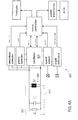
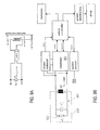
- FIG. 6A shows an exemplary realization of a drilling system 600 equipped with an inductive sensor and a corresponding evaluation device.
- a coil 622 which constitutes a sensor device according to the invention, comprised of a drill bit 610, is connected via a transformer transformer 641, which has a Signal transmission, for example, from the drill bit 610 to the engine or vice versa, excited by an oscillator 620 in resonance.
- This can be done for example by a simple RLC oscillator, which automatically resonates or by excitation of a resonant circuit with a constant frequency ⁇ 0, for example, with a square wave.
- the phase between current and voltage is regulated to zero.
- Characteristic of the realization of Figure 6A is that a capacitance C P is connected in parallel to the transformer inductance M and the sensor inductance Z s , so that a parallel resonant circuit via the transformer transformer 741 is formed.
- the detection of the (engine) speed and the determination of the Angle of rotation of the drill bit optional features of the invention.
- the current angle of rotation of the drill bit is preferably via a measurement of the Rotor speed and by a reference encoder on the spindle or the Drill bit determined.
- the engine speed is at today's drills Usually already detected for a speed control. What's added is one digital Hall sensor, i. a Hall switch, near the tool holder or spindle, the rotation angle of the spindle and thus the drill bit once recorded per assignment.
- This can be a simple notch or knob on the Be output shaft or at a suitable location in the transmission. In this case must used by a permanent magnet biased Hall sensor become. It is also possible, a permanent magnet to the output shaft to install. In this case, the Hall switch need not be biased.
- This complex variant is equal to an impedance measuring bridge.
- this variant has the basic function of an impedance bridge, but is in terms of accuracy, linearity and absolute measurement error not with one Laboratory instrument such as the well-known Precision Impedance Analyzer, Agilent 4294A, the company Agilent Technologies Co. Ltd. comparable.
- the measured values as such are not as important as the sensitivity of the measuring circuit.
- the measuring circuit is therefore preferably trimmed for high sensitivity.
- the available measuring signals can be both a change the impedance as well as a change in the resonant frequency, the in each case conclusion on the presence of a reinforcing iron or a allow other ferromagnetic article.
- the impedance of the entire Resonant circuit i. the sensor device with the transformer, purely ohmic. Of the Imaginary part falls away. If the resonant circuit with a constant Current amplitude operated, can via a measurement of the voltage amplitude over the coupling transformer readily to the impedance closed become.
- the following table presents the advantages and disadvantages of some impedance measurement techniques applicable to the measurement of the impedance of a sensor coil located in a drill bit that changes, for example, by approaching an iron. Further details of the impedance measurement methods presented can be found in "The Impedance Measurement Handbook: A Guide to Measurement Technologies and Techniques", which is available from Agilent Technologies Co. Ltd. for example, at http://cp.literature.agilent.com/litweb/pdf/5950-3000.pdf. method advantages disadvantage applicable frequency range bridge methods High accuracy (0.1% typ.). Wide frequency coverage by using different types of bridges. Low cost. Must be calibrated manually. Narrow frequency coverage with one instrument. DC up to 300 MHz resonance method Good quality accuracy up to high quality values.
- the proximity of a ferromagnetic object can also be determined by the change the resonant frequency of the sensor device and the transformer determine the existing overall system. Because a linear dependence between the measuring or evaluation signal and the distance between iron and coil not is necessary if primarily the earliest possible detection of a reinforcing iron is set to the goal, the resonance frequency is a meaningful and sensitive measured variable
- f / V "frequency to voltage", i.e. frequency-to-voltage converter
- a Lowering the resonance frequency indicates a reinforcing iron.
- the signal value which is finally evaluated, is the difference of the resonance frequency without coupling by a reinforcing iron (offset, initial frequency) and the resonance frequency in the presence of a reinforcing iron.
- S k ⁇ [ f res ( L S0 ) - f res ( L S ( x ))]
- the block diagram depicted in FIG. 7A shows an exemplary realization of a drilling system 700 equipped with an inductive sensor and a corresponding evaluation device.
- a coil 722 which represents a sensor device according to the invention encompassed by a drill bit 710
- a transformer transformer 741 which allows signal transmission, for example from the drill bit 710 to the prime mover or vice versa, excited by an oscillator 720 in resonance.
- This can be done for example by a simple RLC oscillator, which automatically resonates or by excitation of a resonant circuit with a constant frequency ⁇ 0, for example, with a square wave.
- the phase between current and voltage is regulated to zero.
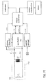
- Figure 7A While the block diagram of Figure 7A represents a complex variant, the even allows an angle-faithful evaluation of the measured signals, Figure 7B shows a simplified variant, in the example only the amplitude and the Frequency of the oscillator signal and the engine or drive speed detected become. Also in the embodiment of Figure 7B is a series resonant circuit 752 via the transformer transformer 741 formed.
- FIG. 8A shows an exemplary embodiment analogous to FIGS. 6A, 7A and 7B Invention in which, however, the signal path between the sensor as a device acting sensor coil 822 and a measuring and evaluation circuit via a capacitive transformer 842 runs.
- a capacitive transformer 842 allows a signal transmission between a prime mover and a relative to Drive machine rotating drill bit.
- the capacitive can be Coupling element in the tool holder in the form of a cylindrical capacitor as radial embodiment or plate capacitor as axial Accommodate embodiment.
- Cooling water as a material with a high dielectric constant as Dielectric be used between the plates.
- Eddy current sensors are a standard tool for NDT (non-destructive testing: non-destructive testing) of electrically conductive, in particular metallic structures. Thus, e.g. in aircraft construction the carrying elements examined for cracks. An eddy current sensor reacts both on the permeability as well as on the inductance of the target. More about For example, eddy current measurement can be found in Scott D. Welsby and Tim Hitz. Nov. 1997, "True Position Measurement with Eddy Current Technology," Sensors, Vol. 14, no. 11: 30-40 can be found.
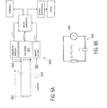
- Figure 9A shows a general arrangement for eddy current measurement.
- An eddy current sensor provides a preferred sensor device of the invention a corresponding drill bit or a corresponding drilling system and a corresponding measuring and evaluation device can be by means of implement the following features in a preferred manner.
- Coupler transfer to the rotating drill bit: Coupling transformer.
- Measuring electronics LRC resonant circuit with high-frequency (5-50kHz) constant current source.
- engine speed via a Hall sensor on the rotor of the device.
- Signal evaluation Evaluation of the measuring voltage synchronous to the motor speed: Representation of the measuring signal as a function of the drill bit angle and cumulation of the measuring signals, moving away of the DC background and noise, setting a threshold and display.
- FIG. 9B shows a possible realization a drill bit 910 according to the invention with eddy current sensor as Sensor device in the context of a drilling system with a corresponding measuring and evaluation device.
- the main component of the eddy current sensor forms a sensor coil 922, the mainly inductive impedance Z S, for example, together with the also mainly inductive impedance M of a transformer transformer 941 and a capacitor Cp LRC resonant circuit 952 forms.
- the measuring device includes a conventional oscillator 920, the LRC resonant circuit 952 with a given frequency f 0 and stimulates a constant current amplitude I 0th
- the oscillation frequency is either determined by the resonant frequency of the LRC resonant circuit 952, or is specified as forced oscillation by the microcontroller. For example, via a rectifier with a downstream low-pass filter, the voltage amplitude of the resulting oscillation of the LRC resonant circuit 952 is measured.
- the impedance is then calculated in a microcontroller functioning as an evaluation device: Z ( x ) U I 0 ⁇ Z 2 0 a ⁇ ( x + b )
- a simple and inexpensive oscillator circuit for such a driver circuit is an LC logic gate oscillator using CMOS logic gates. This can, as shown, be realized on the basis of two inverters.
- the two inverters produce a strong positive voltage gain. Therefore, the circuit oscillates at a frequency at which the phase shift of the resonant sensor is just disappearing.
- the output voltage is a rectangular voltage whose frequency is a function of the distance x between the coil and the reinforcing iron.
- this output voltage can For the purpose of evaluating this measurement signal, i. this output voltage, can For example, a microcontroller as an evaluation the frequency of Output voltage via a counter input, a so-called counter input, digitize, which counts the output pulses per unit of time.
- f ( x ) 1 2 ⁇ L ( x ) ⁇ ( C cable + C IWC + C p )
- V pp is the amplitude of the fundamental harmonics of the square wave signal at the output. It suffices to consider only this first harmonic since R S and the LC circuit form a bandpass filter around the oscillation frequency. This filter attenuates all components except the fundamental component. It makes sense to select the peak-to-peak amplitude Vpp at least as large as half the supply voltage V DD when the coil is unloaded, ie, when no reinforcing iron is in the vicinity. This rule implies that R S ⁇ R res , where R res is determined in the unloaded state, ie without any reinforcing iron in the vicinity. The higher the resistance at resonance, the less power is required for the operation of the sensor. The resistance increases with increasing frequency, increasing inductance and higher Q quality.
- the frequency response of an eddy current sensor depends on both the conductivity as well as the permeability of the environment it sensor, in particular one to detecting targets.
- An alternative measuring and evaluation circuit provide the proximity switches of OM series from Philips.
- FIG. 9E shows, as an example of this type series, the proximity switch OM 286 oscillator operating at T1, D1 oscillates at a frequency determined by C1 and the coil N1, N2 is given. If the coil, for example, by approach damped by a reinforcing iron, the vibrations break off, the working point T1 shifts, and the Schmitt trigger consisting of T2, T3 switches. Over the power stage (T4), then, e.g. a relay switched or an LED operated. About the resistance R, the sensitivity of the Adjust proximity sensor.
- a two-wire Hall sensor provides a preferred sensor device of the Invention.
- a corresponding drill bit or a corresponding Drilling system and a corresponding measuring and evaluation can be realize by means of the following features in a preferred manner.
- Coupler, transfer to the rotating drill bit slip ring, earth potential.
- a shunt resistor is used to measure the current consumption of the Hall element, followed by a low-pass filter, amplifier and A / D converter, microprocessor.
- Measuring signal (s) Hall voltage.
- engine speed via a Hall sensor on the rotor of the device.
- Signal evaluation Evaluation of the measuring voltage synchronous to the motor speed: Representation of the measuring signal as a function of the Bohrkronenwinkels and cumulation of the measured signals, moving away of the DC background and noise, setting a threshold and display.
- Two-wire Hall sensors provide a measurement signal in the form of power consumption. They use an internal power source, depending on the strength of the magnetic field is changed. About a series resistor, the current and thus the Magnetic field can be measured as a voltage. In other words, one changes integrated Hall sensor circuit, their current consumption, i. their DC resistance over the source. Does the magnetic flux density change near the sensor, so also changes its power consumption. This can, for example, with a Series resistance can be measured.
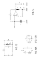
- FIG. 10 shows an exemplary realization of a device according to the invention Drill bit 1010 with a sensor device 1020 based on a two-wire Hall sensor 1021H, wherein the drill bit 1010 part of a with a corresponding evaluation device equipped drilling system 1000 forms.
- the sensor device 1020 also includes a permanent magnet 1028, referred to as Magnetic field source for the Hall sensor 1021H acts.
- a slip ring 1043 ago As a sensible way of signal transmission between the 1010 with the drill bit rotating sensor device 1020 and the example in a Drive machine arranged measuring device, sees the embodiment the use of a slip ring 1043 ago. This can be done on the upper shaft of the Drill bit 1010 an isolated collector, i. a slip ring 1043 mounted Be isolated with the positive potential of the Hall sensor 1021H connected is. The earth potential 1144 for the supply of the Hall sensor 1021H is guided over the device ground and over the drill bit 1010 itself. This saves a slip ring.
- the slip ring 1043 is for example by means of brushes tapped in the tool holder of the drive machine.
- a coupling transformer together with a rectifier on the secondary side i. on the at the Drill bit mounted side of the transformer, find use.
- the rectifier supplies power to the Hall sensor.
- the current consumption of the Hall sensor hangs from the magnetic flux density. The current consumption can over the Power consumption (or over the current) on the primary side of the Be measured transformer.
- Ohmic contact elements provide a preferred sensor device of Invention.
- a corresponding drill bit or a corresponding Drilling system and a corresponding measuring and evaluation can be realize by means of the following features in a preferred manner.
- Coupler, transfer to the rotating drill bit slip ring, earth potential.
- a shunt resistor measures the current consumption, followed by a low-pass filter, amplifier and A / D converter, microprocessor.
- Measurement signal (s) Resistance change at the drill segments.
- Signal evaluation Evaluation of the measuring voltage synchronous to the motor speed: Representation of the measuring signal as a function of the drill bit angle and cumulation of the measuring signals, moving away of the DC background and noise, setting a threshold and display.
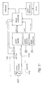
- FIG. 11 shows an exemplary realization of a device according to the invention Drill bit 1110 with a sensor device based on ohmic Contact elements 1127.
- Such contact elements 1127 can, for example by conducting in a degrading matrix 416 of the drill bit 1110, conductive Elements 425 are realized, as shown in Figures 4A to 4F.
- ohmic contact elements provides a simple and robust Possibility for the iron detection dar.
- a disadvantage of the method is that a Detection of iron can only be done during drilling. If you do not want the iron For example, an inductive (coil), magnetic (Hall) or eddy current method are used.
- FIG. 11 shows an embodiment in which a Signal transmission between the rotating with the drill bit 1010 Sensor device and one example in a prime mover arranged measuring device via a slip ring 1143 takes place. protection elements against overvoltage when drilling to a live cable are not drawn.
- a circuit of the measuring and evaluation device for example in the Drive machine to the ohmic contact elements in the drill bit can via two slip rings, each having a signal path to or from the Allow drill bit.
- the circuit can, as shown, on the ground potential of the Underground 1144 closed.
- a coupling transformer instead of the slip ring 1143, a coupling transformer be used.
- the transformer will vary depending on the resistance of the Contact elements loaded or even short-circuited on the secondary side. This change in resistance can be due to the power consumption on the Primary side are measured.
- Any local measurement method i. any local probe at one point of the attached to the front end of the drill bit, generates a rotation angle of the Drill bit periodic, pulse-like signal. Whether it is a Hall sensor or is an inductive proximity sensor, actually plays no Role. In the first case, voltage pulses are actually generated, in the second case it is rather pulse-like frequency changes that have to be detected. in the Case of ohmic contact, i. a switch, it is Resistance changes, which in turn, for example, as a voltage change can be detected.
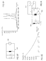
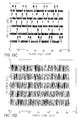
- FIGs. 15A-15D a simulation becomes five different situations discussed. It is assumed that a Reinforcing iron at five different places relative to the center of a Drill bit is drilled.
- Figure 15A shows this simulation assumption. shown is the outline of a drill bit 1510 and five reinforcing bars 1581A-1581E. The intersections of a respective Arm michseisens 1581 through the drill bit 1510 are marked by dots.
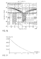
- Figure 15B shows the simulated, normalized resistance change of a ohmic contacts obtained measurement signal as a function of the rotation angle of the Drill bit 1510 in rad.
- the illustrated Meßsignalverrise correspond from top to bottom by detecting the respective reinforcing iron 1581A to 1581E expected Me ⁇ signalverlauf.
- the lowest curve thus corresponds a detection of armouring 1581E.
- the in Meßsignalverlauf occurring pulses are wide and relatively close together. The closer that Reinforcing iron is moved towards the center of the drill bit, the more The pulse distribution becomes more symmetrical, and the pulses become shorter.
- FIG. 15C illustrates an analogous situation in which no resistance values, but (normalized) voltage values of a (digital, i.e. analogue Hall sensor with Schmitt trigger) Hall sensors can be simulated.
- the pulses are comparable, only the sign is reversed.
- FIG. 15D shows a schematic illustration the simulated frequency change of, for example, in a degrading Element of the drill bit 1510 arranged, inductive proximity sensor.
- the frequency was chosen very low, which does not correspond to reality.
- the frequency digitized directly via a counter input of a microcontroller and thus be translated into a numeric value.
- f / V converter For an analog pulse detection offers a frequency-voltage converter (f / V converter).
- a pulse detection is preferably done in a microcontroller. As soon as a peak is detected, ie as soon as the voltage at the input of an A / D converter of the microcontroller has exceeded a certain threshold U thr , and the length of the pulse does not correspond to drill bit longer than a quarter turn, the pulse is considered detected. For safety, a second pulse can be waited for, which also fulfills these conditions. Only then does the reinforcing iron apply as detected.
- a target has been detected, this circumstance can be displayed to the user and / or appropriate actions can be initiated (e.g., engine switch off, stop feed motor).
- a robust and preferred evaluation method for all local measuring methods is based on a synchronous measurement of the angle of rotation of the drill bit. Become the measuring signals (whether it is an impedance change, a change of Resonant frequency or a change in resistance) as a function of Rotation angle modulo 2 ⁇ represented, so will always be at the angle where For example, an iron is detected, signals accumulate. Will the Angular range in e.g. ten sectors are classified as 36 ° (sector classes) and the summed mean signal amplitudes within a respective sector, so are in areas where a reinforcing iron is actually, the Cumulate signals while the noise in the remaining areas is averaged out. An underground caused by the "DC offset" said DC offset can be easily determined and subtracted become. The signals accumulated in the sectors exceed a certain amount Threshold, this is displayed, for example, or the drive is stopped.
- the accumulated classes are reset to zero.
- the reset can also be triggered manually by the user.
- a Alternative is that the accumulated signals within the classes by means of a Very slow high-pass filter (cutoff frequency, for example, 15-30 sec) entrained become.
- cutoff frequency for example, 15-30 sec
- an indicator in the form of a ring of LED around the tool holder.
- the LEDs can be activated according to the amount of detection. This not only indicates to the user that a rebar has been encountered or will soon be encountered, but also where the rebar (approximately) is located.
- the coil is not locally in place of a grinding element of Drill bit is attached, but for example axially around the drill bit is wound, is similar to a metal detector.
- the coil is as far as possible at the front end of the drill bit, just behind the drill bit Abrasive elements.
- the lateral surface of the drill bit made of non-metallic material. Provide fiber reinforced composites Here is a preferred solution.
- the diamond segments at the end of Drill bit still attached to a metallic ring.
- the signal evaluation consists in this case of the determination of a certain Minimum threshold which the output signal of the metal detector must reach so that a reinforcing iron has been detected with certainty.
- Metal detectors can also be realized with oscillator circuits, which with a quality or frequency change to the presence of iron react. (see the section "Eddy current sensors”)
- the evaluation of a directly from the sensor device or indirectly via a preceding measuring device supplied measuring signal in a measuring device or in a specially provided for this purpose Evaluation device done.
- the evaluation can be done solely on the basis of the o.g. Measuring signal or in conjunction with other parameters, in particular in Related to further drilling parameters such as cutting speed, Pressing force, water supply, torque, etc., take place.
- the Evaluation as a function of predetermined, measured and / or of a Users of a drilling system according to the invention supplied parameters.
- the evaluation result and / or one or more of the other parameters can be returned to the measuring device and / or the sensor device Become a better, especially a user's requirements adapted to achieve evaluation result.
- the user might determine via an appropriate input device, if rather a high Detection sensitivity in which a target is detected early, i. also from big Distance, is detected, or rather a high detection accuracy, in which little "false messages" occur, is desired.
- the cutting speed as a parameter to choose between Detection accuracy and detection sensitivity are used, wherein when drilled quickly through the drilling surface, rather the sensitivity the detection is emphasized, but when slowly drilled through the underground is, greater value may be placed on the detection accuracy.
- a greater detection sensitivity could be achieved, for example be arranged that several in the degrading area of the drill bit Sensor devices are switched on, while, for example, a larger Detection angle accuracy could be achieved that only one in a limited extent of the drill bit detecting sensor device is switched on.
- the measuring and evaluation device can be both analog and digital Components include. Also they can be in the form of a programmable Hardware be executed, whose operation via an appropriate Program software is determined.
- the drilling system comprises a signaling device incorporated in Depending on the measurement and / or evaluation signal an adjustment of or automatically performs a plurality of Bohrparameters, and / or a user a Adjustment of one or more drill parameters perceptibly signaled and / or a user perceive an exchange of the drill bit signals, and / or a user the detection of a target perceptible, in particular visually and angled, signaled, and / or the drilling process automatically stops.
- the adaptation comprises one or more Bohrparameters an adjustment of the torque, the cutting speed, the water supply, the contact pressure and / or the drilling power.
- FIG. 16 shows a schematic illustration of a signaling device 1660 a drilling system according to the invention 1660 according to another Embodiment.
- the illustrated signaling device 1660 comprises a microcontroller 1653 and a display device connected thereto 1661.
- the microcontroller 1653 is also equipped with 1671 power electronics connected via the microcontroller 1653 a drive the drill bit serving drive device 1673 and the feed of the drill bit Serving feed device 1672 can regulate.
- the display device 1661 is designed in the form of a ring whose outer perimeter LEDs are mounted at regular intervals.
- the Ring has, for example, a contacting and fastening element which a signal transmission between the display device 1661 and the Microcontroller 1653 via a corresponding contact element on the housing of Drive machine allows, and the ring in a unique position in the Attached ratio to the prime mover.
- the Display device attachable to the tool holder.
- a drill bit according to the invention as well as a drilling system according to the invention may include one or more sensor devices and / or Signalgebervorrichept exhibit. These are preferably to be aligned in a manner that a optimal target detection, preferably optimal detection sensitivity, or other preferred evaluation result in a preferred Detection direction, preferably in the drilling direction guaranteed.
- the sensor devices and / or Signalgebervorrichungen rotationally symmetric or rotationally asymmetric to Rotation axis of the drill bit in or on the drill bit or in or on one Drive machine can be arranged.
- sensor devices and / or Signalgebervorrichiers are mechanically and / or electrically too to ensure a long service life of these devices.
- This protection can be realized that the sensor devices and / or Signalgebervorrichonne in one of the mechanical and electrical Load corresponding potting compound, a corresponding metal or in corresponding recesses of the drill bit are encapsulated.
- the sensor devices and / or Signalgebervorrichache and a Measuring and evaluation device extending signal lines preferably protect.
- Embodiments of a suitable rotary Signal transmission connection for example, in connection with the Embodiments of Figures 2E, 8A, 4F and 5A described in detail, why at this point to a repetition of the local statements is waived.
- the principle that will suggest here uses the effect of detuning a (not necessarily resonant) resonant circuit by a change in the Sensor coil impedance.
- Figure 6B shows a coupling of an oscillator 620 to a parallel resonant circuit 652 by means of a transformer in the form of a coupling transformer 641 in a schematic representation.
- the resonant circuit 652 is formed, for example, from the sensor coil 622, a capacitance C P and the inductance M of the coupling transformer 641, ie the transformer inductance M.
- the impedance Z S of the sensor coil 622 includes both an inductive 622L (L s ) and a real 622R (R s ) portion; the capacitance C P is connected in parallel to the transformer inductance M.
- the resonant frequency of the system is greatly different from the Sensor inductance depends.
- the resonant frequency depends quite linearly on the Sensor inductance from.
- the resonant frequency f res falls from 53 kHz to 40 kHz using the same values as above according to the function shown in FIG. 6G. This shows that the resonant circuit is not dominated by the transformer inductance, but is quite sensitive to a small change in the sensor inductance L S.
- FIG. 6H shows the behavior of the impedance according to the above equation for different sensor inductance values.
- the impedance can also be calculated directly without having to calculate equivalent parallel inductances and shunt resistances.
- FIG. 6I shows how a drill bit 610 with a sensor element 622 ( Z S ) can be coupled to an LC oscillator 620, which is preferably formed in or on a drive machine for the drill bit, not shown, via a coupling transformer 641.
- the parallel capacitance C P of a parallel resonant circuit 652 can be arranged on the drill bit itself.
- FIG. 6J The reduced equivalent circuit diagram shown in FIG. 6J shows that it is in fact a conventional parallel resonant circuit 652 with the components L PP and C P.
- a series resonant circuit with transformer transformer can be to Signal measurement and transmission in a drilling system according to the invention make sense.
- This is a capacity on the drill bit opposite side of the transformatory transformer in series with the Connected transformer.
- the capacity for example, part of a Drive machine, which in the drilling system for driving the drill bit Use, or even part of a corresponding measuring and / or Form evaluation circuit.
- FIG. 7C shows a series resonant circuit 752 with transformer transformer in which the T-equivalent circuit diagram 741 'of the transformatory transformer used analogously to Figure 6C instead of the transformer transformer has been.
- L PP L S ⁇ M L S + M
- ⁇ res L S + L ⁇ + M C ⁇ ( L 2 ⁇ + L S ⁇ L ⁇ + 2M ⁇ L ⁇ + L S ⁇ M )
- the resonant frequency f res falls from about 35 kHz to 30.5 kHz using the same values as above according to the function shown in FIG. 6G. This shows that the resonant circuit is not dominated by the transformer inductance, but is quite sensitive to a small change in the sensor inductance L S.
- a high-frequency alternating current In the sensor coil By applying a high-frequency alternating current In the sensor coil, eddy currents form in the reinforcing iron.
- This second rung in the rebar can be like the secondary coil of a Transformers are treated, the low on the mutual inductance Primary coil couples.
- the system sensor coil armouring iron can in a equivalent equivalent circuit to be converted whose impedance from the Mutual inductance M (x) between sensor coil and conductive surface of the Reinforcing iron and thus strongly from the distance x between the sensor coil and Iron surface depends.
- FIG. 9C shows the general course of the inductance and the equivalent loss resistance as a function of the distance. From this it can be seen that the loss resistance R eq is almost hyperbolic for larger distances, while it saturates for small values at a certain maximum value. This is because for small distances x no longer the entire flux penetrates the sensor coil. While the change in the equivalent resistance is almost one order of magnitude, the inductance change is only 5-10%. R eq ( x ) ⁇ a x + b
- a first option is to use a constant-frequency LC oscillator Amplitude response. Damp eddy current losses due to the proximity of the iron this oscillator, and the amplitude of the oscillation decreases. Disadvantageous In this approach, nonlinearities of the oscillator (e.g., as a function of the Temperature) itself affect the amplitude response, and that the Amplitude change is not a linear function of the distance x.
- ⁇ Z Z ( ⁇ R S / R S ) 2 1+ Q 2 + ( .delta..sub.L / L ) 2 1 + 1 / Q 2
- This phase angle can be achieved by means of a phase-sensitive rectifier be detected and compensated.
- FIG. 13A shows a series resonant circuit
- FIG. 13B shows a parallel resonant circuit.
- the resistance represents the Losses of the coil.
- Inductive sensors in resonant circuits typically consist of a single coil. For this reason, the distance characteristic (the inductance L as a function of the distance of the reinforcing iron) is also not linear. But since the resonance frequency is proportional to 1 / ( LC ) 1 ⁇ 2 , the frequency-spacing characteristic shows a more linear behavior.
- a preferred as the invention measuring circuit component oscillator the relatively stable PIERCE oscillator, as used for example in "Systemtechnik inductive displacement and force transducer. Receivers and connecting devices ", by Horst R Loos, publication date: 1992, ISBN: 3816905412 is described. He can from a transistor circuit with a grounded base and a capacitive Coupling between the emitter and the collector can be realized.
- a so-called Colpitts oscillator is particularly suitable for use as Inventive Meßscenskomponente suitable. Regarding the execution such an oscillator is based on the relevant literature on oscillators directed.
- the real part does not change; only the inductance decreases.
Landscapes
- Engineering & Computer Science (AREA)
- Mechanical Engineering (AREA)
- Mining & Mineral Resources (AREA)
- Investigating Or Analyzing Materials By The Use Of Magnetic Means (AREA)
- Arrangements For Transmission Of Measured Signals (AREA)
- Drilling And Boring (AREA)
Applications Claiming Priority (2)
| Application Number | Priority Date | Filing Date | Title |
|---|---|---|---|
| DE102004020672A DE102004020672A1 (de) | 2004-04-28 | 2004-04-28 | Bohrkrone, Bohrsystem und Verfahren zur Bestimmung des elektromagnetischen Umfeldes einer Bohrkrone |
| DE102004020672 | 2004-04-28 |
Publications (2)
| Publication Number | Publication Date |
|---|---|
| EP1591182A2 true EP1591182A2 (fr) | 2005-11-02 |
| EP1591182A3 EP1591182A3 (fr) | 2012-05-09 |
Family
ID=34939279
Family Applications (1)
| Application Number | Title | Priority Date | Filing Date |
|---|---|---|---|
| EP05102946A Withdrawn EP1591182A3 (fr) | 2004-04-28 | 2005-04-14 | Trépan de forage, système de forage et procédé pour déterminer l'environnement électromagnétique d'un trépan de forage |
Country Status (2)
| Country | Link |
|---|---|
| EP (1) | EP1591182A3 (fr) |
| DE (1) | DE102004020672A1 (fr) |
Cited By (6)
| Publication number | Priority date | Publication date | Assignee | Title |
|---|---|---|---|---|
| DE102013205827A1 (de) * | 2013-04-03 | 2014-10-09 | Hilti Aktiengesellschaft | Vorschubeinrichtung |
| CN109715325A (zh) * | 2016-09-23 | 2019-05-03 | 喜利得股份公司 | 取芯钻头 |
| CN113758652A (zh) * | 2021-09-03 | 2021-12-07 | 中国南方电网有限责任公司超高压输电公司广州局 | 换流变压器漏油检测方法、装置、计算机设备和存储介质 |
| EP4140675A1 (fr) * | 2021-08-25 | 2023-03-01 | Hilti Aktiengesellschaft | Dispositif de forage des matériaux pierreux et procédé de forage des matériaux pierreux armés |
| CN119147033A (zh) * | 2024-11-20 | 2024-12-17 | 长春理工大学 | 一种用于电磁环境下传感器的检测装置 |
| CN120798318A (zh) * | 2025-09-04 | 2025-10-17 | 山东科技大学 | 一种嵌入导电金属滚珠的磨损自检截齿 |
Families Citing this family (3)
| Publication number | Priority date | Publication date | Assignee | Title |
|---|---|---|---|---|
| DE102014204833A1 (de) * | 2014-03-14 | 2015-09-17 | Werner Kluft | Vorrichtung, Werkzeugmaschine und Verfahren zum Messen und Überwachen von Werkzeugen bzw. Werkstücken |
| DE102015200617A1 (de) * | 2015-01-16 | 2016-07-21 | Zf Friedrichshafen Ag | Induktive Positionsbestimmung |
| CN112091301A (zh) * | 2020-09-17 | 2020-12-18 | 中国航发贵州黎阳航空动力有限公司 | 铣床切圆的刀具 |
Family Cites Families (14)
| Publication number | Priority date | Publication date | Assignee | Title |
|---|---|---|---|---|
| DE3132251A1 (de) * | 1980-08-15 | 1982-06-09 | British Aerospace Public Ltd. Co., London | Vorrichtung zur feststellung der gegenseitigen ausrichtung von teilen |
| DE3207747A1 (de) * | 1982-03-04 | 1983-09-08 | Schützeichel, Johannes, 5466 Neustadt | Einrichtung zur ueberwachung von bohr- und saegearbeiten in bauwerkskoerpern, insbesondere spannbeton-bauwerken |
| DE3324615A1 (de) * | 1982-11-27 | 1984-05-30 | Robert Bosch Gmbh, 7000 Stuttgart | Vorrichtung zum auffangen von bohrklein |
| US4647853A (en) * | 1983-09-30 | 1987-03-03 | Teleco Oilfield Services Inc. | Mud turbine tachometer |
| DE3637128A1 (de) * | 1986-10-31 | 1988-05-05 | Hilti Ag | Einrichtung zur automatischen werkzeugspezifischen betriebsdateneinstellung eines elektrischen antriebsgeraets fuer auswechselbare werkzeuge |
| DE4008304A1 (de) * | 1990-03-15 | 1991-09-19 | Hessabi Iradj | Bohrvorrichtung, insbesondere zum bohren wandparalleler kabelkanaele |
| DE4027020C2 (de) * | 1990-08-27 | 1994-08-25 | Heinrich Liebig Gmbh | Verfahren und Vorrichtung zur Feststellung des Vorhandenseins von metallischen Bewehrungselementen im Innern eines Beton-Bauteils |
| GB2288027B (en) * | 1994-03-31 | 1998-02-04 | Western Atlas Int Inc | Well logging tool |
| DE19833823A1 (de) * | 1998-07-28 | 2000-02-10 | Schluemer Heinz Dieter | Vorrichtung zur Bestimmung von Bohrlochmittelpunkten bzw. Bauteilkanten an geschlossenen Oberflächen mit exakter Lagevorgabe des gewünschten Bohrungsmittelpunktes bzw. der Bauteilkante, von der für die arbeitende Person (Werker) unzugänglichen Seite der Oberfläche |
| EP1072903A1 (fr) * | 1999-07-27 | 2001-01-31 | Oxford Instruments (Uk) Limited | Appareil de mesure par résonance magnétique nucléaire pendant le forage d'un puits |
| WO2002012676A1 (fr) * | 2000-08-08 | 2002-02-14 | Emtec Solutions Limited | Appareil et procede de telemetrie |
| WO2002056047A1 (fr) * | 2001-01-12 | 2002-07-18 | Oxford Instruments Superconductivity Limited | Ensemble generateur de champ magnetique et procede |
| CA2547584C (fr) * | 2001-04-25 | 2008-11-18 | Halliburton Energy Services, Inc. | Procede, systeme et outil pour evaluation d'un gisement et essai d'un puits pendant des operations de forage |
| DE10225518B4 (de) * | 2002-06-10 | 2004-07-08 | Rayonex Schwingungstechnik Gmbh | Verfahren und Vorrichtung zur Steuerung und Positionsbestimmung eines Instruments oder Gerätes |
-
2004
- 2004-04-28 DE DE102004020672A patent/DE102004020672A1/de not_active Ceased
-
2005
- 2005-04-14 EP EP05102946A patent/EP1591182A3/fr not_active Withdrawn
Cited By (10)
| Publication number | Priority date | Publication date | Assignee | Title |
|---|---|---|---|---|
| DE102013205827A1 (de) * | 2013-04-03 | 2014-10-09 | Hilti Aktiengesellschaft | Vorschubeinrichtung |
| CN109715325A (zh) * | 2016-09-23 | 2019-05-03 | 喜利得股份公司 | 取芯钻头 |
| CN109715325B (zh) * | 2016-09-23 | 2020-08-11 | 喜利得股份公司 | 取芯钻头 |
| US11504779B2 (en) | 2016-09-23 | 2022-11-22 | Hilti Aktiengesellschaft | Core drill bit |
| EP4140675A1 (fr) * | 2021-08-25 | 2023-03-01 | Hilti Aktiengesellschaft | Dispositif de forage des matériaux pierreux et procédé de forage des matériaux pierreux armés |
| CN113758652A (zh) * | 2021-09-03 | 2021-12-07 | 中国南方电网有限责任公司超高压输电公司广州局 | 换流变压器漏油检测方法、装置、计算机设备和存储介质 |
| CN113758652B (zh) * | 2021-09-03 | 2023-05-30 | 中国南方电网有限责任公司超高压输电公司广州局 | 换流变压器漏油检测方法、装置、计算机设备和存储介质 |
| CN119147033A (zh) * | 2024-11-20 | 2024-12-17 | 长春理工大学 | 一种用于电磁环境下传感器的检测装置 |
| CN119147033B (zh) * | 2024-11-20 | 2025-02-11 | 长春理工大学 | 一种用于电磁环境下传感器的检测装置 |
| CN120798318A (zh) * | 2025-09-04 | 2025-10-17 | 山东科技大学 | 一种嵌入导电金属滚珠的磨损自检截齿 |
Also Published As
| Publication number | Publication date |
|---|---|
| DE102004020672A1 (de) | 2005-11-17 |
| EP1591182A3 (fr) | 2012-05-09 |
Similar Documents
| Publication | Publication Date | Title |
|---|---|---|
| DE60309678T2 (de) | Gepulste drehmoment, kraft oder allgemeine messung mit spule und magnetfeldsensor (tangential, umfang) | |
| EP3274527B1 (fr) | Serrure ou ferrure de fenêtre ou de porte | |
| DE3840532C2 (fr) | ||
| DE102008058457A1 (de) | Verfahren und handgeführter Sensor mit adaptiver Detektionsschwelle zur Detektion von in Bauwerkuntergründen eingebetteten Fremdobjekten | |
| DE60130890T2 (de) | Induktive Sensoranordnung und Verfahren zur Erfassung von eisernen Objekten | |
| DE3435812A1 (de) | Geraet zur messung der drehgeschwindigkeit eines rotierenden elements | |
| WO2013087283A2 (fr) | Détecteur de métaux | |
| EP1591182A2 (fr) | Trépan de forage, système de forage et procédé pour déterminer l'environnement électromagnétique d'un trépan de forage | |
| EP0551606B1 (fr) | Détecteur de métaux | |
| DE102005002238A1 (de) | Sensor zur Ortung metallischer Objekte sowie Messgerät mit einem solchen Sensor | |
| EP2884236A1 (fr) | Capteur inductif de couple et d'angle de rotation doté d'une unité d'indication de position à circuit oscillant | |
| DE102009010943A1 (de) | Betriebsverfahren und Spulenanordnung für einen magnetischen Sensor zur Detektion metallischer Objekte in einem Untergrund | |
| EP1538424A1 (fr) | Dispositif de mesure de position à micro-ondes pour un entraínement direct électrodynamique | |
| EP1869505B1 (fr) | Procede pour localiser des objets enfermes dans un milieu et appareil de mesure pour la mise en oeuvre dudit procede | |
| EP2834601B1 (fr) | Procédé et ensemble pour déterminer la position d'un composant | |
| DE102007033745B4 (de) | Induktive Drehzahlerkennung | |
| EP3108210B1 (fr) | Dispositif de détection et procédé de détermination d'une position et/ou d'un changement de position d'un objet à mesurer | |
| DE102011085876A1 (de) | Objektfinder | |
| DE4027020C2 (de) | Verfahren und Vorrichtung zur Feststellung des Vorhandenseins von metallischen Bewehrungselementen im Innern eines Beton-Bauteils | |
| DE102006053023A1 (de) | Induktiver Näherungsschalter | |
| EP3314310B1 (fr) | Dispositif et procédé de détection d'un objet | |
| EP3574297B1 (fr) | Capteur de force magnétique et sa fabrication | |
| DE102004006680B3 (de) | Sensorvorrichtung zur Prüfung von Oberflächen | |
| DE102005019095A1 (de) | Längenmessgerät | |
| DE19841325A1 (de) | Verfahren und Vorrichtung zur zerstörungsfreien Bestimmung des Abstandes zu einem metallischen Gegenstand in nichtmetallischer und unmagnetischer Umgebung und/oder zur Bestimmung seiner geometrischen Dimension |
Legal Events
| Date | Code | Title | Description |
|---|---|---|---|
| PUAI | Public reference made under article 153(3) epc to a published international application that has entered the european phase |
Free format text: ORIGINAL CODE: 0009012 |
|
| AK | Designated contracting states |
Kind code of ref document: A2 Designated state(s): AT BE BG CH CY CZ DE DK EE ES FI FR GB GR HU IE IS IT LI LT LU MC NL PL PT RO SE SI SK TR |
|
| AX | Request for extension of the european patent |
Extension state: AL BA HR LV MK YU |
|
| PUAL | Search report despatched |
Free format text: ORIGINAL CODE: 0009013 |
|
| AK | Designated contracting states |
Kind code of ref document: A3 Designated state(s): AT BE BG CH CY CZ DE DK EE ES FI FR GB GR HU IE IS IT LI LT LU MC NL PL PT RO SE SI SK TR |
|
| AX | Request for extension of the european patent |
Extension state: AL BA HR LV MK YU |
|
| RIC1 | Information provided on ipc code assigned before grant |
Ipc: B23B 51/02 20060101AFI20120403BHEP |
|
| 17P | Request for examination filed |
Effective date: 20121109 |
|
| AKX | Designation fees paid |
Designated state(s): AT CH DE FR GB IT LI |
|
| 17Q | First examination report despatched |
Effective date: 20160928 |
|
| STAA | Information on the status of an ep patent application or granted ep patent |
Free format text: STATUS: EXAMINATION IS IN PROGRESS |
|
| STAA | Information on the status of an ep patent application or granted ep patent |
Free format text: STATUS: THE APPLICATION IS DEEMED TO BE WITHDRAWN |
|
| 18D | Application deemed to be withdrawn |
Effective date: 20170411 |