EP1591299B1 - Zusatz-stromversorgung für fahrzeug - Google Patents
Zusatz-stromversorgung für fahrzeug Download PDFInfo
- Publication number
- EP1591299B1 EP1591299B1 EP20040706314 EP04706314A EP1591299B1 EP 1591299 B1 EP1591299 B1 EP 1591299B1 EP 20040706314 EP20040706314 EP 20040706314 EP 04706314 A EP04706314 A EP 04706314A EP 1591299 B1 EP1591299 B1 EP 1591299B1
- Authority
- EP
- European Patent Office
- Prior art keywords
- power
- inverter
- type
- voltage
- electric
- Prior art date
- Legal status (The legal status is an assumption and is not a legal conclusion. Google has not performed a legal analysis and makes no representation as to the accuracy of the status listed.)
- Expired - Lifetime
Links
Images

Classifications
-
- B—PERFORMING OPERATIONS; TRANSPORTING
- B60—VEHICLES IN GENERAL
- B60L—PROPULSION OF ELECTRICALLY-PROPELLED VEHICLES; SUPPLYING ELECTRIC POWER FOR AUXILIARY EQUIPMENT OF ELECTRICALLY-PROPELLED VEHICLES; ELECTRODYNAMIC BRAKE SYSTEMS FOR VEHICLES IN GENERAL; MAGNETIC SUSPENSION OR LEVITATION FOR VEHICLES; MONITORING OPERATING VARIABLES OF ELECTRICALLY-PROPELLED VEHICLES; ELECTRIC SAFETY DEVICES FOR ELECTRICALLY-PROPELLED VEHICLES
- B60L1/00—Supplying electric power to auxiliary equipment of vehicles
-
- B—PERFORMING OPERATIONS; TRANSPORTING
- B60—VEHICLES IN GENERAL
- B60L—PROPULSION OF ELECTRICALLY-PROPELLED VEHICLES; SUPPLYING ELECTRIC POWER FOR AUXILIARY EQUIPMENT OF ELECTRICALLY-PROPELLED VEHICLES; ELECTRODYNAMIC BRAKE SYSTEMS FOR VEHICLES IN GENERAL; MAGNETIC SUSPENSION OR LEVITATION FOR VEHICLES; MONITORING OPERATING VARIABLES OF ELECTRICALLY-PROPELLED VEHICLES; ELECTRIC SAFETY DEVICES FOR ELECTRICALLY-PROPELLED VEHICLES
- B60L1/00—Supplying electric power to auxiliary equipment of vehicles
- B60L1/02—Supplying electric power to auxiliary equipment of vehicles to electric heating circuits
-
- B—PERFORMING OPERATIONS; TRANSPORTING
- B60—VEHICLES IN GENERAL
- B60L—PROPULSION OF ELECTRICALLY-PROPELLED VEHICLES; SUPPLYING ELECTRIC POWER FOR AUXILIARY EQUIPMENT OF ELECTRICALLY-PROPELLED VEHICLES; ELECTRODYNAMIC BRAKE SYSTEMS FOR VEHICLES IN GENERAL; MAGNETIC SUSPENSION OR LEVITATION FOR VEHICLES; MONITORING OPERATING VARIABLES OF ELECTRICALLY-PROPELLED VEHICLES; ELECTRIC SAFETY DEVICES FOR ELECTRICALLY-PROPELLED VEHICLES
- B60L1/00—Supplying electric power to auxiliary equipment of vehicles
- B60L1/02—Supplying electric power to auxiliary equipment of vehicles to electric heating circuits
- B60L1/04—Supplying electric power to auxiliary equipment of vehicles to electric heating circuits fed by the power supply line
- B60L1/10—Supplying electric power to auxiliary equipment of vehicles to electric heating circuits fed by the power supply line with provision for using different supplies
-
- B—PERFORMING OPERATIONS; TRANSPORTING
- B60—VEHICLES IN GENERAL
- B60L—PROPULSION OF ELECTRICALLY-PROPELLED VEHICLES; SUPPLYING ELECTRIC POWER FOR AUXILIARY EQUIPMENT OF ELECTRICALLY-PROPELLED VEHICLES; ELECTRODYNAMIC BRAKE SYSTEMS FOR VEHICLES IN GENERAL; MAGNETIC SUSPENSION OR LEVITATION FOR VEHICLES; MONITORING OPERATING VARIABLES OF ELECTRICALLY-PROPELLED VEHICLES; ELECTRIC SAFETY DEVICES FOR ELECTRICALLY-PROPELLED VEHICLES
- B60L1/00—Supplying electric power to auxiliary equipment of vehicles
- B60L1/14—Supplying electric power to auxiliary equipment of vehicles to electric lighting circuits
-
- B—PERFORMING OPERATIONS; TRANSPORTING
- B60—VEHICLES IN GENERAL
- B60L—PROPULSION OF ELECTRICALLY-PROPELLED VEHICLES; SUPPLYING ELECTRIC POWER FOR AUXILIARY EQUIPMENT OF ELECTRICALLY-PROPELLED VEHICLES; ELECTRODYNAMIC BRAKE SYSTEMS FOR VEHICLES IN GENERAL; MAGNETIC SUSPENSION OR LEVITATION FOR VEHICLES; MONITORING OPERATING VARIABLES OF ELECTRICALLY-PROPELLED VEHICLES; ELECTRIC SAFETY DEVICES FOR ELECTRICALLY-PROPELLED VEHICLES
- B60L2200/00—Type of vehicles
- B60L2200/26—Rail vehicles
-
- B—PERFORMING OPERATIONS; TRANSPORTING
- B60—VEHICLES IN GENERAL
- B60L—PROPULSION OF ELECTRICALLY-PROPELLED VEHICLES; SUPPLYING ELECTRIC POWER FOR AUXILIARY EQUIPMENT OF ELECTRICALLY-PROPELLED VEHICLES; ELECTRODYNAMIC BRAKE SYSTEMS FOR VEHICLES IN GENERAL; MAGNETIC SUSPENSION OR LEVITATION FOR VEHICLES; MONITORING OPERATING VARIABLES OF ELECTRICALLY-PROPELLED VEHICLES; ELECTRIC SAFETY DEVICES FOR ELECTRICALLY-PROPELLED VEHICLES
- B60L2210/00—Converter types
- B60L2210/20—AC to AC converters
-
- H—ELECTRICITY
- H02—GENERATION; CONVERSION OR DISTRIBUTION OF ELECTRIC POWER
- H02J—ELECTRIC POWER NETWORKS; CIRCUIT ARRANGEMENTS OR SYSTEMS FOR SUPPLYING OR DISTRIBUTING ELECTRIC POWER; SYSTEMS FOR STORING ELECTRIC ENERGY
- H02J1/00—Circuit arrangements for DC mains or DC distribution networks
- H02J1/10—Parallel operation of DC sources
-
- H—ELECTRICITY
- H02—GENERATION; CONVERSION OR DISTRIBUTION OF ELECTRIC POWER
- H02M—APPARATUS FOR CONVERSION BETWEEN AC AND AC, BETWEEN AC AND DC, OR BETWEEN DC AND DC, AND FOR USE WITH MAINS OR SIMILAR POWER SUPPLY SYSTEMS; CONVERSION OF DC OR AC INPUT POWER INTO SURGE OUTPUT POWER; CONTROL OR REGULATION THEREOF
- H02M1/00—Details of apparatus for conversion
- H02M1/0003—Details of control, feedback or regulation circuits
- H02M1/0006—Arrangements for supplying an adequate voltage to the control circuit of converters
-
- Y—GENERAL TAGGING OF NEW TECHNOLOGICAL DEVELOPMENTS; GENERAL TAGGING OF CROSS-SECTIONAL TECHNOLOGIES SPANNING OVER SEVERAL SECTIONS OF THE IPC; TECHNICAL SUBJECTS COVERED BY FORMER USPC CROSS-REFERENCE ART COLLECTIONS [XRACs] AND DIGESTS
- Y02—TECHNOLOGIES OR APPLICATIONS FOR MITIGATION OR ADAPTATION AGAINST CLIMATE CHANGE
- Y02T—CLIMATE CHANGE MITIGATION TECHNOLOGIES RELATED TO TRANSPORTATION
- Y02T10/00—Road transport of goods or passengers
- Y02T10/60—Other road transportation technologies with climate change mitigation effect
- Y02T10/72—Electric energy management in electromobility
Definitions
- the present invention relates to vehicle auxiliary electric-power-supplying systems that supply low-voltage power, which is converted from high-voltage power, to loads such as an air conditioner and lighting fixtures installed in an electric vehicle.
- an electric vehicle has a back-up battery therein.
- a vehicle is provided therein with a vehicle auxiliary electric-power-supplying system that converts high-voltage power supplied from an overhead wire, to low-voltage power, and supplies the low-voltage power to a load installed in the vehicle. Only when electric power has been supplied from the back-up battery voltage to a controller of the vehicle auxiliary electric-power-supplying system, and the controller has operated, the entire vehicle auxiliary electric-power-supplying system has become ready to start. However, when voltage of the back-up battery decreases and does not reach enough voltage to operate the controller, the controller does not start to operate, resultantly the entire vehicle-auxiliary-electric-power-supplying system does not operate.
- an electric power supplier (converter) has been provided for converting the high-voltage power, which is supplied from the overhead wire, to the low-voltage power, and supplying the electric power (electric power source) to the controller (control circuit), when the vehicle auxiliary electric-power-supplying system starts to operate.
- the controller in the vehicle auxiliary electric-power-supplying system normally operates with electric power being supplied from the power supplier.
- the power supplier in order to reduce its frequency in use, operates only when the vehicle auxiliary electric-power-supplying system starts to operate, then the operation is stopped after electric power has been obtained from output of an electric power inverter. If any short-circuit malfunction occurs during the starter stop, due to an affect such as a dielectric breakdown on the low-voltage side between the electric power inverter and the load, in order to stop the output from the electric power inverter, the controller needs to command the electric power inverter to stop operation.
- DE 1 292 697 B discloses a vehicle auxiliary electric power suppling system comprising an electric power inverter for converting a first type of dc power received through an overhead wire to a second type of dc power.
- the second type of dc power is supplied to a dc load.
- an electric power supplier receives the second type of dc power.
- the electric power supplier takes energy from a battery and supplies it to the electric power inverter.
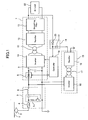
- Numeral 3 denotes an automatic starter, which is composed of a fuse 4, an electromagnetic contactor 5, and an input filter reactor 6.
- an electromagnetic contactor 5 a coil, a switch, and a resistor for decreasing voltage are represented.
- a contactor which is not illustrated, is provided between the resistor and the coil.
- a controller described later detects any excessive voltage inputted through the pantograph 2, and opens the contactor; as a result, current will not flow through the coil, enabling the switch to open. Because the contactor is normally closed, the starter automatically starts to operate; the coil is excited; the switch is closed; and then, the high-voltage power is applied to the vehicle auxiliary electric-power-supplying system. In response to excessive current through the overhead wire 1, by the fuse 4 breaking up, the connection between the overhead wire 1 and the circuits in the vehicle auxiliary electric-power-supplying system is disconnected.
- Numeral 7 denotes an electric power inverter, which is composed of a charging switch 8, an input filter capacitor 9, an inverter 10, a transformer 11, a rectifier 12, and a smoothing filter 13.
- the electric power inverter 7 converts to low-voltage dc power high-voltage dc power inputted from the automatic starter 3, and supplies the low-voltage power to a load and the vehicle auxiliary electric-power-supplying system.
- a smoothing operation for the voltage obtained through the overhead wire 1 is performed using the input filter reactor 6 and the input filter capacitor 9.
- the charging switch 8 controls, for the purpose of protecting the input filter capacitor 9 when the vehicle starts to operate, the electric charging based on the controller described later.
- the inverter 10 is used for converting dc electric power into ac.
- Numeral 15 is an electric power supplier, which is composed of an inverter 16, a transformer 17, and a rectifier 18.
- the power supplier 15 converts to low-voltage dc power the high-voltage dc power obtained through the automatic starter 3.
- the voltage outputted from the power supplier 15 is lower than the voltage outputted from the electric power inverter 7. Both the voltages are controlled by the coil configurations of the transformer 11 and transformer 17.
- Numeral 19 is a butt-jointed diode, in which each cathode of a diode 20 and a diode 21 is butt-jointed, and connected to the controller 14. Anodes of the butt-jointed diode 19 each are connected to the smoothing filter 13 and rectifier 18, respectively. Due to the butt-jointed diode 19, higher voltage power of either the power supplied from the electric power inverter 7 or power supplier 15 is supplied to the controller 14. Although voltages of the above described electric power supplied to the butt-jointed diode 19 are different from each other, the electric power inverter 7 and the power supplier 15 are configured so that both the voltages fall within an electric power supplying range in which the controller 14 can normally operate.
- Numeral 22 denotes a dc load such as lighting fixtures, to which the low-voltage dc power is supplied from the smoothing filter 13.
- the high-voltage power through the pantograph 2 is supplied to the automatic starter 3.
- the automatic starter 3 is an input protector for protecting the power inverter 7 or power supplier 15 in the following stage against excessive high-voltage power.
- the high-voltage power having passed through the automatic starter 3 is supplied to the charging switch 8 in the electric power inverter 7 and the inverter 16 in the power supplier 15.
- the charging switch 8 has not operated.
- the power supplier 15 operates based on the high-voltage power supplied.
- the high-voltage power is converted from dc into ac by the inverter 16, and transformed to low-voltage by the transformer 17.
- the transformed low-voltage ac power is rectified into low-voltage dc power by the rectifier 18.
- the rectified low-voltage power is supplied to the diode 21 of the butt-jointed diode 19.
- the electric power is not supplied from the electric power inverter 7, and the voltage of the power supplied to the diode 21 of the butt-jointed diode 19 becomes higher than the other; therefore, the electric power is supplied to the controller 14 as the electric power source.
- the controller 14 With electric power being supplied from this source, the controller 14 operates.
- the controller 14 detects a charging state (voltage, etc.) of the input filter capacitor 9, and, based on control information (not illustrated) that has been preinstalled in the controller 14, outputs to the charging switch 8 control signals in response to the detection result.
- the charging switch 8 controls current, when the system starts to operate, from the input filter reactor 6 to the input filter capacitor 9 based on the control signals, and protects the input filter capacitor 9 from being rapidly charged.
- the input filter capacitor 9 is charged up to the same voltage as that of the overhead wire 1.
- the controller 14 After the input filter capacitor 9 has been charged up, the controller 14 outputs control signals to the inverter 10.
- the high-voltage dc power supplied to the inverter 10 is converted into ac based on the control signals. After having been converted into ac, the electric power is transformed to low-voltage by the transformer 11, and rectified into the low-voltage dc power by the rectifier 12. Then, the low-voltage dc power is smoothed by the smoothing filter, and supplied to the dc load 22 and to the diode 20 of the butt-jointed diode 19.
- the power supplier 15 does not stop operation and remains in a standby status so as to enable electric power to be supplied at any time. If the high/low voltage relationship between the diode 20 and diode 21 is inverted, the electric power is supplied from the rectifier 18 to the controller 14 through the diode 21.
- the butt-jointed diode 19 has three roles.
- the first role is to prevent the electric power from being supplied from the power supplier 15 to the dc load 22.
- the second is, in order to reduce the frequency in use for circuit elements composing the power supplier 15, to automatically switch the electric power source, which supplies power to the controller 14, from the power supplier 15 to the electric power inverter 7, after the electric power inverter 7 has started to operate and the power therefrom has been obtained.
- the last is to automatically switch the electric power source, which supplies power to the controller 14, from output of the electric power inverter 7 to that of the power supplier 15, because the output voltage of the power supplier 15 becomes higher than that of the electric power inverter 7, if power from the electric power inverter 7 cannot be obtained due to a malfunction, etc.
- the pantograph 2 and the fuse 4 may be configured so as to be separable.
- a contactor in order to prevent battery consumption, a contactor may be provided so as to enable the smoothing filter 13 and the backup battery to be suitably separated.
- the system is configured in such a way that the automatic starter 3 that automatically starts normally without control by the controller 14, and the electric power inverter 7that needs control by the controller 14 are separated; therefore, after the operation till the automatic starter 3 has been performed, and when the operation of the controller 14 is needed, the power supplier 15 finally starts to operate. Consequently, the operation of the power supplier 15 during the time when the controller 14 does not need to operate, can be prevented.
- the electric power is selectively supplied to the controller of the vehicle auxiliary electric-power-supplying system by voltages outputted from the backup battery and the power supplier being butted at each other, if the voltage of the backup battery has not reach a suppliable voltage to the controller, even if the entire vehicle auxiliary electric-power-supplying system is in operation, the power supplier has continued to supply electric power to the controller until the voltage of the backup battery is charged up to the suppliable voltage.
- Embodiment 2 a vehicle auxiliary electric-power-supplying system in which both ac electric power and dc electric power are outputted is explained in Embodiment 2.
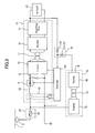
- Fig. 2 is a view illustrating a configuration of the vehicle auxiliary electric-power-supplying system according to Embodiment 2.
- numeral 23 denotes an electric power inverter
- numeral 24 denotes an inverter
- numeral 25 denotes a smoothing filter
- numerals 26 and 27 denote transformers
- numeral 28 denotes an ac load.
- the ac load 28 includes an air conditioner.
- Other numerals are the same elements as those represented in Embodiment 1.
- the low-voltage ac power (single-phase electric power-output) from the transformer 26 is supplied to the transformer 27.
- the supplied electric power is further transformed to low-voltage power by the transformer 27, and then rectified by the rectifier 12 from ac into dc.
- the low-voltage dc power having been smoothed by the smoothing filter 13 is supplied to the dc load 22 and the diode 20 of the butt-jointed diode 19.
- the transformer 27 and the rectifier 12 are used, the ac three-phase power outputted from the transformer 26 may instead be rectified intact using a three-phase bridge-rectifying-circuit.
- Fig. 3 is a view illustrating a vehicle auxiliary electric-power-supplying system according to Embodiment 3 of the present invention.
- numeral 29 denotes an automatic starter having a fuse 30.
- Numeral 31 denotes an electric power inverter,
- numeral 32 denotes an electromagnetic contactor,
- numeral 33 denotes an input filter reactor, and
- numeral 35 denotes a controller.
- Other numerals are the same as those represented in Embodiment 1.
- the electromagnetic contactor 5 has been automatically started to operate using a resistor that can decrease the voltage until the system can start to operate; however, in some areas, because the voltage of the overhead wire 1 is so high that there may be cases in which an electromagnetic contactor having voltage-resistant characteristics for enabling automatic start is not available, or the vehicle auxiliary electric-power-supplying system becomes upsized due to the upsized resistor needed for decreasing the voltage to a voltage with which the electromagnetic contactor can automatically start to operate.
- the automatic starter 29 in which any command from the controller 35 is not needed, when the system starts to operate is composed of only the fuse 30.
- the electromagnetic contactor 32 and the input filter reactor 33 are installed in the electric power inverter 31 in which a command from the controller 35 is needed.
- the fuse 30 prevents excessive current from flowing from the overhead wire 1 to the electric power inverter 31.
- the controller 35 detects the voltage, etc. from the automatic starter 29 (not illustrated), and controls coils of the electromagnetic contactor 32. A switch therein is opened/closed by the action of the coils.
- the electromagnetic contactor 32 is configured in such a way that the resistor for decreasing the voltage, in order to automatically start to operate, has been removed, and the controller 35 controls the contactor accordingly.
- the controller 35 detects the voltage of the electric power from the automatic starter 29, owing to the power-outputting from the diode 21 (not illustrated). In a case in which the voltage is higher than the voltage that the electric power inverter 31 can permit, by the controller 35 controlling the coils of the electromagnetic contactor 32, the switch is opened; consequently, the electric power inverter 31 is protected against excessive voltage through the overhead wire 1. On the other hand, in a case in which the voltage is within the permissible range, by the controller 35 controlling the coils of the electromagnetic contactor 32, the coils are excited and the switch is closed, and then the input filter reactor 33, the charging switch 8, and the input filter capacitor 9 are turned active.
- the fuse 30 and the electromagnetic contactor 32 each are a protector for protecting, against the electric power through the overhead wire 1, the power inputting into the electric power inverter 31.
- the electromagnetic contactor 32 is operated by the controller 35 controlling.
- the inverter 10 After the input filter capacitor 9 has been charged, by the controller 35 controlling, the inverter 10 is operated; consequently, the high-voltage dc power is converted into ac. Moreover, by the transformer 11, the rectifier 12, and the smoothing filter 13, the ac power is changed into low-voltage dc power. If any power-output is obtained from the electric power inverter 31, power-output from the diode 20 of the butt-jointed diode 19 is supplied to the controller 35 as an electric power source.
- Embodiment 3 Because the vehicle auxiliary electric-power-supplying system according to Embodiment 3 is configured as described above, an effect similar to that in Embodiment 1 can be obtained.
- the vehicle auxiliary electric-power-supplying system will not be upsized.
- the vehicle auxiliary electric-power-supplying system can be obtained, in which the frequency in use for the power supplier is prevented as low as possible, and the electric power inverter operation can be normally stopped by electric power being immediately started to be supplied from the power supplier to the controller even in a case in which normal electric power has become unable to be obtained from the output of the electric power inverter.
- the present invention is useful in electric vehicles to realize a vehicle auxiliary electric-power-supplying system, in which the frequency in use for the power supplier is prevented as low as possible, and the electric power inverter operation can be normally stopped by electric power being immediately started to be supplied from the power supplier to the controller even in a case in which normal electric power has become unable to be obtained from the output of the electric power inverter.
Landscapes
- Engineering & Computer Science (AREA)
- Power Engineering (AREA)
- Transportation (AREA)
- Mechanical Engineering (AREA)
- Electric Propulsion And Braking For Vehicles (AREA)
Claims (7)
- Zusatzstromversorgungssystem für Fahrzeuge, das Folgendes aufweist:- einen Stromwechselrichter (7), der einen Wechselrichter (10), einen Transformator (11) und einen Gleichrichter (12) aufweist und dazu ausgebildet ist, einen ersten Gleichstrom-Typ, der über eine Oberleitung (1) empfangen wird, in einen zweiten Gleichstrom-Typ umzuwandeln sowie den zweiten Gleichstrom-Typ einer Gleichstromlast (22) zuzuführen;- eine elektrische Stromversorgungseinrichtung (15), die einen Wechselrichter (16), einen Transformator (17) und einen Gleichrichter (18) aufweist und dazu ausgebildet ist, den über die Oberleitung (1) empfangenen ersten Gleichstrom-Typ in einen dritten Gleichstrom-Typ umzuwandeln;- eine Stromabgabeeinheit (19), die aus einer stumpf-verbundenen Diode (19) gebildet ist, die aus einer ersten Diode (20), der der zweite Gleichstrom-Typ zugeführt wird, und aus einer zweiten Diode (21), der der dritte Gleichstrom-Typ zugeführt wird, aufgebaut ist und die sowohl mit dem Stromwechselrichter (7) als auch der Stromversorgungseinrichtung (15) verbunden ist sowie dazu ausgebildet ist, den Gleichstrom mit höherer Spannung entweder vom zweiten Gleichstrom-Typ oder vom dritten Gleichstrom-Typ abzugeben; und- eine Steuerung (14), die dazu ausgebildet ist, Strom von der Stromabgabeeinheit (19) zu empfangen sowie den Stromwechselrichter (7) zu steuern.
- System nach Anspruch 1,
wobei der Stromwechselrichter (7) einen Schalter (8) aufweist, der zum Steuern des Stroms von einer Oberleitung (1) ausgebildet ist, wobei der Schalter (8) das Umwandeln des ersten Gleichstrom-Typs in den zweiten Gleichstrom-Typ auf der Basis von Steuersignalen steuert, die von der Steuerung (14) abgegeben werden. - System nach Anspruch 1 oder 2,
wobei das System dazu ausgebildet ist, der Steuerung (14) den dritten Gleichstrom-Typ über die Stromabgabeeinheit (19) zuzuführen, wenn das System den Betrieb aufnimmt, sowie den zweiten Gleichstrom-Typ über die Stromabgabeeinheit (19) zuzuführen, nachdem der zweite Gleichstrom-Typ von dem Stromwechselrichter (7) abgegeben worden ist. - System nach einem der Ansprüche 1 bis 3,
wobei das System dazu ausgebildet ist, der Steuerung (14) den dritten Gleichstrom-Typ über die Stromabgabeeinheit (19) zuzuführen, wenn die Spannung vom zweiten Gleichstrom-Typ niedriger wird als die Spannung vom dritten Gleichstrom-Typ. - System nach einem der Ansprüche 1 bis 4,
das weiterhin Folgendes aufweist:eine erste Schutzeinrichtung (3), die zwischen die Oberleitung (1) und den Stromwechselrichter (7) geschaltet ist und dazu ausgebildet ist, den Stromwechselrichter (7) vor dem durch die Oberleitung (1) zugeführten ersten Gleichstrom-Typ zu schützen. - System nach Anspruch 5,
wobei der erste Gleichstrom-Typ der Stromversorgungseinrichtung (15) über die erste Schutzeinrichtung (3) zugeführt wird. - System nach einem der Ansprüche 1 bis 6,
wobei der Stromwechselrichter (23) dazu ausgebildet ist, den ersten Gleichstrom-Typ in einen vierten Typ von Wechselstrom umzuwandeln sowie den vierten Typ von Wechselstrom einer Wechselstromlast (28) zuzuführen.
Applications Claiming Priority (1)
| Application Number | Priority Date | Filing Date | Title |
|---|---|---|---|
| PCT/JP2004/000829 WO2005073014A1 (ja) | 2004-01-29 | 2004-01-29 | 車両用補助電源装置 |
Publications (3)
| Publication Number | Publication Date |
|---|---|
| EP1591299A1 EP1591299A1 (de) | 2005-11-02 |
| EP1591299A4 EP1591299A4 (de) | 2009-03-25 |
| EP1591299B1 true EP1591299B1 (de) | 2014-10-08 |
Family
ID=34816500
Family Applications (1)
| Application Number | Title | Priority Date | Filing Date |
|---|---|---|---|
| EP20040706314 Expired - Lifetime EP1591299B1 (de) | 2004-01-29 | 2004-01-29 | Zusatz-stromversorgung für fahrzeug |
Country Status (7)
| Country | Link |
|---|---|
| US (1) | US7728456B2 (de) |
| EP (1) | EP1591299B1 (de) |
| JP (1) | JP4635874B2 (de) |
| CN (1) | CN1329221C (de) |
| CA (1) | CA2506221C (de) |
| ES (1) | ES2522278T3 (de) |
| WO (1) | WO2005073014A1 (de) |
Families Citing this family (21)
| Publication number | Priority date | Publication date | Assignee | Title |
|---|---|---|---|---|
| KR100902507B1 (ko) | 2007-04-17 | 2009-06-15 | 삼성전자주식회사 | 전력 조절장치 및 그 운영방법 |
| CN101293485B (zh) * | 2007-04-27 | 2011-01-26 | 杰生自动技术有限公司 | 一种交通工具外接电器电力管理方式及其装置 |
| DE102009008549A1 (de) * | 2009-02-12 | 2010-08-19 | Bombardier Transportation Gmbh | Anordnung zum Betreiben von Verbrauchern in einem Schienenfahrzeug mit elektrischer Energie, wahlweise aus einem Energieversorgungsnetz oder aus einer Motor-Generator-Kombination |
| DE102009045639A1 (de) * | 2009-10-13 | 2011-04-14 | Robert Bosch Gmbh | Elektrische Verbindungsvorrichtung für Hybrid- und Elektrofahrzeuge sowie zugehöriges Verfahren zur Aufladung |
| JP5349698B2 (ja) * | 2010-11-19 | 2013-11-20 | 三菱電機株式会社 | 車両用補助電源装置 |
| CA2856668C (en) * | 2011-11-24 | 2016-09-13 | Mitsubishi Electric Corporation | Auxiliary power source device for vehicle |
| KR101369052B1 (ko) * | 2012-05-21 | 2014-03-04 | 엘에스산전 주식회사 | 전기자동차용 인버터-충전기 통합장치 |
| GB2504754B (en) * | 2012-08-09 | 2018-07-04 | Safran Power Uk Ltd | Aircraft engine electrical apparatus |
| CN104604086B (zh) * | 2012-09-05 | 2017-03-08 | 三菱电机株式会社 | 车站电源装置 |
| CN103856075A (zh) * | 2012-12-03 | 2014-06-11 | 永济新时速电机电器有限责任公司 | 基于列车辅助电气系统的转换模块及列车辅助电气系统 |
| JP6139236B2 (ja) * | 2013-04-16 | 2017-05-31 | 株式会社東芝 | 電気機関車制御装置 |
| CN104626998B (zh) * | 2015-02-13 | 2017-03-08 | 苏州凯博易控驱动技术有限公司 | 一体式智能集电器 |
| KR101696999B1 (ko) * | 2015-03-10 | 2017-01-16 | 엘에스산전 주식회사 | 에너지 저장 장치의 제어 방법 및 전력 관리 시스템 |
| CN106160206A (zh) | 2015-03-31 | 2016-11-23 | 通用电气公司 | 电源系统及能量存储系统 |
| JP6553992B2 (ja) * | 2015-09-07 | 2019-07-31 | 東洋電機製造株式会社 | 補助電源装置 |
| CN107294381B (zh) * | 2016-03-31 | 2021-05-04 | 法雷奥汽车内部控制(深圳)有限公司 | 提供差分电压的装置和方法以及直流-直流转换器 |
| JP6501976B2 (ja) * | 2016-07-04 | 2019-04-17 | 三菱電機株式会社 | 駅舎電源装置および帯電検知方法 |
| US20200198676A1 (en) * | 2017-06-16 | 2020-06-25 | Mitsubishi Electric Corporation | Vehicle starting system, remote control system, integrated train management system, and automatic train controller |
| CN109591598B (zh) * | 2018-10-26 | 2022-03-08 | 南京中欧威能新能源动力系统有限公司 | 一种新能源汽车附加储能机构及使用方法 |
| CN110277823B (zh) | 2019-06-06 | 2021-06-15 | 华为技术有限公司 | 供电电路和逆变器 |
| CN110293850A (zh) * | 2019-06-13 | 2019-10-01 | 宝鸡中车时代工程机械有限公司 | 具有接触网供电电源系统的轨道工程车 |
Family Cites Families (22)
| Publication number | Priority date | Publication date | Assignee | Title |
|---|---|---|---|---|
| DE1292697B (de) * | 1964-10-21 | 1969-04-17 | Bbc Brown Boveri & Cie | Selbstgefuehrter Umrichter zur Gleichspannungsumformung fuer elektrische Triebfahrzeuge |
| ATE2728T1 (de) | 1979-08-29 | 1983-03-15 | Fried. Krupp Gesellschaft Mit Beschraenkter Haftung | Einrichtung zur versorgung von nutzverbrauchern, insbesondere in einem schienenfahrzeug. |
| JPS63174501A (ja) * | 1987-01-14 | 1988-07-19 | Toshiba Corp | 電気車の制御装置 |
| JP2764723B2 (ja) * | 1988-01-06 | 1998-06-11 | 株式会社日立製作所 | 電気車の制御装置 |
| JPH01259704A (ja) * | 1988-04-08 | 1989-10-17 | Toshiba Corp | 電気車の補助電源装置 |
| JPH0270201A (ja) * | 1988-09-03 | 1990-03-09 | Fuji Electric Co Ltd | 車輌用補助電源装置 |
| JPH03261301A (ja) * | 1990-03-08 | 1991-11-21 | Mitsubishi Electric Corp | インバータ装置 |
| JPH0488883A (ja) * | 1990-07-31 | 1992-03-23 | Toshiba Corp | 車両用電力変換装置 |
| JPH05115101A (ja) * | 1991-10-23 | 1993-05-07 | Mitsubishi Electric Corp | 車両用補助電源装置 |
| JPH06178551A (ja) | 1992-12-10 | 1994-06-24 | Toshiba Corp | 電力変換装置の過電圧保護装置 |
| JPH0731135A (ja) | 1993-07-08 | 1995-01-31 | Mitsubishi Electric Corp | 補助電源装置 |
| JPH08182105A (ja) * | 1994-12-21 | 1996-07-12 | Toshiba Corp | 電気車制御装置 |
| JPH08289483A (ja) * | 1995-04-18 | 1996-11-01 | Rohm Co Ltd | 電源回路 |
| JP3245334B2 (ja) * | 1995-08-03 | 2002-01-15 | 本田技研工業株式会社 | 電動車両の電源制御装置 |
| US6075717A (en) * | 1996-05-01 | 2000-06-13 | General Electric Company | PWM rectifier control with switching losses equally distributed among multiple switching devices |
| JPH09308254A (ja) | 1996-05-09 | 1997-11-28 | Toshiba Corp | 補助電源装置 |
| JP3560766B2 (ja) * | 1997-05-13 | 2004-09-02 | 株式会社東芝 | 電力変換装置 |
| JP3361047B2 (ja) * | 1998-01-30 | 2003-01-07 | 株式会社東芝 | 車両用電源装置 |
| JP3965244B2 (ja) * | 1998-04-20 | 2007-08-29 | オイレス工業株式会社 | 摺動部材用樹脂組成物及びこれを使用した摺動部材 |
| JP2002027601A (ja) * | 2000-07-03 | 2002-01-25 | Mitsubishi Electric Corp | 車両用補助電源装置 |
| TWI269518B (en) * | 2001-04-06 | 2006-12-21 | Delta Electronics Inc | Power supply system having AC redundant and function of protecting AC power form electricity-inversed plug-in |
| US6958552B2 (en) * | 2002-04-10 | 2005-10-25 | Adc Dsl Systems, Inc. | Failsafe power oring with current sharing |
-
2004
- 2004-01-29 ES ES04706314.4T patent/ES2522278T3/es not_active Expired - Lifetime
- 2004-01-29 WO PCT/JP2004/000829 patent/WO2005073014A1/ja not_active Ceased
- 2004-01-29 US US10/541,245 patent/US7728456B2/en not_active Expired - Fee Related
- 2004-01-29 CN CNB2004800014386A patent/CN1329221C/zh not_active Expired - Lifetime
- 2004-01-29 CA CA2506221A patent/CA2506221C/en not_active Expired - Fee Related
- 2004-01-29 EP EP20040706314 patent/EP1591299B1/de not_active Expired - Lifetime
- 2004-01-29 JP JP2005517352A patent/JP4635874B2/ja not_active Expired - Fee Related
Also Published As
| Publication number | Publication date |
|---|---|
| CA2506221C (en) | 2012-03-06 |
| US7728456B2 (en) | 2010-06-01 |
| CN1717346A (zh) | 2006-01-04 |
| JP4635874B2 (ja) | 2011-02-23 |
| EP1591299A1 (de) | 2005-11-02 |
| HK1086234A1 (en) | 2006-09-15 |
| US20060145542A1 (en) | 2006-07-06 |
| WO2005073014A1 (ja) | 2005-08-11 |
| ES2522278T3 (es) | 2014-11-14 |
| CA2506221A1 (en) | 2005-07-29 |
| CN1329221C (zh) | 2007-08-01 |
| EP1591299A4 (de) | 2009-03-25 |
| JPWO2005073014A1 (ja) | 2007-08-23 |
Similar Documents
| Publication | Publication Date | Title |
|---|---|---|
| EP1591299B1 (de) | Zusatz-stromversorgung für fahrzeug | |
| JP3245334B2 (ja) | 電動車両の電源制御装置 | |
| EP3561982A1 (de) | Redundantes energieversorgungssystem | |
| US8581535B2 (en) | Drive unit | |
| CN101389505A (zh) | 电驱动车辆 | |
| JP5082450B2 (ja) | 給電設備 | |
| US20130133987A1 (en) | Electricity supply apparatus and an elevator system | |
| CN101687605B (zh) | 运输系统的电源设备 | |
| US20040017176A1 (en) | Industrial truck with charging function | |
| JP2001204137A (ja) | 車両の給電回路 | |
| EP3308996B1 (de) | Hilfsumrichter für ein schienenfahrzeug | |
| US7701077B2 (en) | Secondary power for critical loads for railroad | |
| AU2012361646B2 (en) | Switching power supply device and air conditioner | |
| KR101050202B1 (ko) | 비상조명등 제어회로 및 그 제어방법 | |
| CN101316782A (zh) | 升降机自动着床装置 | |
| JP3406361B2 (ja) | エレベータの停電時運転装置 | |
| KR100719193B1 (ko) | 차량용 보조 전원 장치 | |
| JPH11252701A (ja) | 車両用電源の離線補償装置 | |
| EP3858652B1 (de) | Stromversorgungssystem für einen elektrischen zug und elektrischer zug | |
| JP2001320831A (ja) | 電鉄用電気車 | |
| JP3232007B2 (ja) | 車両用電源装置 | |
| HK1086234B (en) | Auxiliary power supply for vehicle | |
| JPH07281767A (ja) | 冗長化対応電源装置 | |
| CN117774866A (zh) | 车辆电源系统 | |
| CN117734614A (zh) | 车辆电源系统 |
Legal Events
| Date | Code | Title | Description |
|---|---|---|---|
| PUAI | Public reference made under article 153(3) epc to a published international application that has entered the european phase |
Free format text: ORIGINAL CODE: 0009012 |
|
| 17P | Request for examination filed |
Effective date: 20050629 |
|
| AK | Designated contracting states |
Kind code of ref document: A1 Designated state(s): AT BE BG CH CY CZ DE DK EE ES FI FR GB GR HU IE IT LI LU MC NL PT RO SE SI SK TR |
|
| AX | Request for extension of the european patent |
Extension state: AL LT LV MK |
|
| DAX | Request for extension of the european patent (deleted) | ||
| A4 | Supplementary search report drawn up and despatched |
Effective date: 20090223 |
|
| RIC1 | Information provided on ipc code assigned before grant |
Ipc: H02J 9/06 20060101ALI20090217BHEP Ipc: B60L 1/00 20060101ALI20090217BHEP Ipc: B60L 1/10 20060101AFI20090217BHEP |
|
| 17Q | First examination report despatched |
Effective date: 20090929 |
|
| GRAP | Despatch of communication of intention to grant a patent |
Free format text: ORIGINAL CODE: EPIDOSNIGR1 |
|
| RAP1 | Party data changed (applicant data changed or rights of an application transferred) |
Owner name: MITSUBISHI DENKI KABUSHIKI KAISHA |
|
| RIN1 | Information on inventor provided before grant (corrected) |
Inventor name: KUSUBAYASHI, CHIYO |
|
| INTG | Intention to grant announced |
Effective date: 20140417 |
|
| GRAS | Grant fee paid |
Free format text: ORIGINAL CODE: EPIDOSNIGR3 |
|
| GRAA | (expected) grant |
Free format text: ORIGINAL CODE: 0009210 |
|
| AK | Designated contracting states |
Kind code of ref document: B1 Designated state(s): AT BE BG CH CY CZ DE DK EE ES FI FR GB GR HU IE IT LI LU MC NL PT RO SE SI SK TR |
|
| REG | Reference to a national code |
Ref country code: GB Ref legal event code: FG4D |
|
| REG | Reference to a national code |
Ref country code: CH Ref legal event code: NV Representative=s name: NOVAGRAAF INTERNATIONAL SA, CH Ref country code: AT Ref legal event code: REF Ref document number: 690398 Country of ref document: AT Kind code of ref document: T Effective date: 20141015 Ref country code: CH Ref legal event code: EP |
|
| REG | Reference to a national code |
Ref country code: IE Ref legal event code: FG4D |
|
| REG | Reference to a national code |
Ref country code: DE Ref legal event code: R096 Ref document number: 602004045941 Country of ref document: DE Effective date: 20141113 |
|
| REG | Reference to a national code |
Ref country code: ES Ref legal event code: FG2A Ref document number: 2522278 Country of ref document: ES Kind code of ref document: T3 Effective date: 20141114 |
|
| REG | Reference to a national code |
Ref country code: NL Ref legal event code: VDEP Effective date: 20141008 |
|
| REG | Reference to a national code |
Ref country code: AT Ref legal event code: MK05 Ref document number: 690398 Country of ref document: AT Kind code of ref document: T Effective date: 20141008 |
|
| PG25 | Lapsed in a contracting state [announced via postgrant information from national office to epo] |
Ref country code: NL Free format text: LAPSE BECAUSE OF FAILURE TO SUBMIT A TRANSLATION OF THE DESCRIPTION OR TO PAY THE FEE WITHIN THE PRESCRIBED TIME-LIMIT Effective date: 20141008 |
|
| PG25 | Lapsed in a contracting state [announced via postgrant information from national office to epo] |
Ref country code: PT Free format text: LAPSE BECAUSE OF FAILURE TO SUBMIT A TRANSLATION OF THE DESCRIPTION OR TO PAY THE FEE WITHIN THE PRESCRIBED TIME-LIMIT Effective date: 20150209 Ref country code: FI Free format text: LAPSE BECAUSE OF FAILURE TO SUBMIT A TRANSLATION OF THE DESCRIPTION OR TO PAY THE FEE WITHIN THE PRESCRIBED TIME-LIMIT Effective date: 20141008 |
|
| PG25 | Lapsed in a contracting state [announced via postgrant information from national office to epo] |
Ref country code: AT Free format text: LAPSE BECAUSE OF FAILURE TO SUBMIT A TRANSLATION OF THE DESCRIPTION OR TO PAY THE FEE WITHIN THE PRESCRIBED TIME-LIMIT Effective date: 20141008 Ref country code: GR Free format text: LAPSE BECAUSE OF FAILURE TO SUBMIT A TRANSLATION OF THE DESCRIPTION OR TO PAY THE FEE WITHIN THE PRESCRIBED TIME-LIMIT Effective date: 20150109 Ref country code: CY Free format text: LAPSE BECAUSE OF FAILURE TO SUBMIT A TRANSLATION OF THE DESCRIPTION OR TO PAY THE FEE WITHIN THE PRESCRIBED TIME-LIMIT Effective date: 20141008 Ref country code: SE Free format text: LAPSE BECAUSE OF FAILURE TO SUBMIT A TRANSLATION OF THE DESCRIPTION OR TO PAY THE FEE WITHIN THE PRESCRIBED TIME-LIMIT Effective date: 20141008 |
|
| PG25 | Lapsed in a contracting state [announced via postgrant information from national office to epo] |
Ref country code: BE Free format text: LAPSE BECAUSE OF NON-PAYMENT OF DUE FEES Effective date: 20150131 |
|
| REG | Reference to a national code |
Ref country code: DE Ref legal event code: R097 Ref document number: 602004045941 Country of ref document: DE |
|
| PG25 | Lapsed in a contracting state [announced via postgrant information from national office to epo] |
Ref country code: DK Free format text: LAPSE BECAUSE OF FAILURE TO SUBMIT A TRANSLATION OF THE DESCRIPTION OR TO PAY THE FEE WITHIN THE PRESCRIBED TIME-LIMIT Effective date: 20141008 Ref country code: CZ Free format text: LAPSE BECAUSE OF FAILURE TO SUBMIT A TRANSLATION OF THE DESCRIPTION OR TO PAY THE FEE WITHIN THE PRESCRIBED TIME-LIMIT Effective date: 20141008 Ref country code: EE Free format text: LAPSE BECAUSE OF FAILURE TO SUBMIT A TRANSLATION OF THE DESCRIPTION OR TO PAY THE FEE WITHIN THE PRESCRIBED TIME-LIMIT Effective date: 20141008 Ref country code: SK Free format text: LAPSE BECAUSE OF FAILURE TO SUBMIT A TRANSLATION OF THE DESCRIPTION OR TO PAY THE FEE WITHIN THE PRESCRIBED TIME-LIMIT Effective date: 20141008 Ref country code: RO Free format text: LAPSE BECAUSE OF FAILURE TO SUBMIT A TRANSLATION OF THE DESCRIPTION OR TO PAY THE FEE WITHIN THE PRESCRIBED TIME-LIMIT Effective date: 20141008 |
|
| PLBE | No opposition filed within time limit |
Free format text: ORIGINAL CODE: 0009261 |
|
| STAA | Information on the status of an ep patent application or granted ep patent |
Free format text: STATUS: NO OPPOSITION FILED WITHIN TIME LIMIT |
|
| PG25 | Lapsed in a contracting state [announced via postgrant information from national office to epo] |
Ref country code: LU Free format text: LAPSE BECAUSE OF FAILURE TO SUBMIT A TRANSLATION OF THE DESCRIPTION OR TO PAY THE FEE WITHIN THE PRESCRIBED TIME-LIMIT Effective date: 20150129 Ref country code: IT Free format text: LAPSE BECAUSE OF FAILURE TO SUBMIT A TRANSLATION OF THE DESCRIPTION OR TO PAY THE FEE WITHIN THE PRESCRIBED TIME-LIMIT Effective date: 20141008 |
|
| 26N | No opposition filed |
Effective date: 20150709 |
|
| GBPC | Gb: european patent ceased through non-payment of renewal fee |
Effective date: 20150129 |
|
| PG25 | Lapsed in a contracting state [announced via postgrant information from national office to epo] |
Ref country code: MC Free format text: LAPSE BECAUSE OF FAILURE TO SUBMIT A TRANSLATION OF THE DESCRIPTION OR TO PAY THE FEE WITHIN THE PRESCRIBED TIME-LIMIT Effective date: 20141008 |
|
| PG25 | Lapsed in a contracting state [announced via postgrant information from national office to epo] |
Ref country code: GB Free format text: LAPSE BECAUSE OF NON-PAYMENT OF DUE FEES Effective date: 20150129 |
|
| REG | Reference to a national code |
Ref country code: IE Ref legal event code: MM4A |
|
| REG | Reference to a national code |
Ref country code: FR Ref legal event code: PLFP Year of fee payment: 13 |
|
| PG25 | Lapsed in a contracting state [announced via postgrant information from national office to epo] |
Ref country code: IE Free format text: LAPSE BECAUSE OF NON-PAYMENT OF DUE FEES Effective date: 20150129 |
|
| PG25 | Lapsed in a contracting state [announced via postgrant information from national office to epo] |
Ref country code: SI Free format text: LAPSE BECAUSE OF FAILURE TO SUBMIT A TRANSLATION OF THE DESCRIPTION OR TO PAY THE FEE WITHIN THE PRESCRIBED TIME-LIMIT Effective date: 20141008 |
|
| REG | Reference to a national code |
Ref country code: FR Ref legal event code: PLFP Year of fee payment: 14 |
|
| REG | Reference to a national code |
Ref country code: DE Ref legal event code: R084 Ref document number: 602004045941 Country of ref document: DE |
|
| PG25 | Lapsed in a contracting state [announced via postgrant information from national office to epo] |
Ref country code: HU Free format text: LAPSE BECAUSE OF FAILURE TO SUBMIT A TRANSLATION OF THE DESCRIPTION OR TO PAY THE FEE WITHIN THE PRESCRIBED TIME-LIMIT; INVALID AB INITIO Effective date: 20040129 Ref country code: BG Free format text: LAPSE BECAUSE OF FAILURE TO SUBMIT A TRANSLATION OF THE DESCRIPTION OR TO PAY THE FEE WITHIN THE PRESCRIBED TIME-LIMIT Effective date: 20141008 |
|
| REG | Reference to a national code |
Ref country code: ES Ref legal event code: GC2A Effective date: 20170720 |
|
| PG25 | Lapsed in a contracting state [announced via postgrant information from national office to epo] |
Ref country code: TR Free format text: LAPSE BECAUSE OF FAILURE TO SUBMIT A TRANSLATION OF THE DESCRIPTION OR TO PAY THE FEE WITHIN THE PRESCRIBED TIME-LIMIT Effective date: 20141008 |
|
| REG | Reference to a national code |
Ref country code: FR Ref legal event code: PLFP Year of fee payment: 15 |
|
| PGFP | Annual fee paid to national office [announced via postgrant information from national office to epo] |
Ref country code: FR Payment date: 20171211 Year of fee payment: 15 |
|
| PGFP | Annual fee paid to national office [announced via postgrant information from national office to epo] |
Ref country code: CH Payment date: 20180115 Year of fee payment: 15 Ref country code: ES Payment date: 20180201 Year of fee payment: 15 |
|
| PGFP | Annual fee paid to national office [announced via postgrant information from national office to epo] |
Ref country code: DE Payment date: 20190115 Year of fee payment: 16 |
|
| REG | Reference to a national code |
Ref country code: CH Ref legal event code: PL |
|
| PG25 | Lapsed in a contracting state [announced via postgrant information from national office to epo] |
Ref country code: FR Free format text: LAPSE BECAUSE OF NON-PAYMENT OF DUE FEES Effective date: 20190131 |
|
| PG25 | Lapsed in a contracting state [announced via postgrant information from national office to epo] |
Ref country code: CH Free format text: LAPSE BECAUSE OF NON-PAYMENT OF DUE FEES Effective date: 20190131 Ref country code: LI Free format text: LAPSE BECAUSE OF NON-PAYMENT OF DUE FEES Effective date: 20190131 |
|
| REG | Reference to a national code |
Ref country code: ES Ref legal event code: FD2A Effective date: 20200310 |
|
| PG25 | Lapsed in a contracting state [announced via postgrant information from national office to epo] |
Ref country code: ES Free format text: LAPSE BECAUSE OF NON-PAYMENT OF DUE FEES Effective date: 20190130 |
|
| REG | Reference to a national code |
Ref country code: DE Ref legal event code: R119 Ref document number: 602004045941 Country of ref document: DE |
|
| PG25 | Lapsed in a contracting state [announced via postgrant information from national office to epo] |
Ref country code: DE Free format text: LAPSE BECAUSE OF NON-PAYMENT OF DUE FEES Effective date: 20200801 |