EP1592860B1 - Tunnelbohrvorrichtung - Google Patents
Tunnelbohrvorrichtung Download PDFInfo
- Publication number
- EP1592860B1 EP1592860B1 EP03778015A EP03778015A EP1592860B1 EP 1592860 B1 EP1592860 B1 EP 1592860B1 EP 03778015 A EP03778015 A EP 03778015A EP 03778015 A EP03778015 A EP 03778015A EP 1592860 B1 EP1592860 B1 EP 1592860B1
- Authority
- EP
- European Patent Office
- Prior art keywords
- cutter
- head
- hub
- axis
- tunnel
- Prior art date
- Legal status (The legal status is an assumption and is not a legal conclusion. Google has not performed a legal analysis and makes no representation as to the accuracy of the status listed.)
- Expired - Lifetime
Links
- 238000005520 cutting process Methods 0.000 claims abstract description 26
- 238000000034 method Methods 0.000 claims description 7
- 230000002093 peripheral effect Effects 0.000 claims description 2
- 241000237509 Patinopecten sp. Species 0.000 claims 1
- 235000020637 scallop Nutrition 0.000 claims 1
- 239000000463 material Substances 0.000 description 5
- 239000013598 vector Substances 0.000 description 3
- 230000003116 impacting effect Effects 0.000 description 2
- 230000001154 acute effect Effects 0.000 description 1
- 238000005065 mining Methods 0.000 description 1
- 230000035515 penetration Effects 0.000 description 1
- 239000011435 rock Substances 0.000 description 1
Images


Classifications
-
- E—FIXED CONSTRUCTIONS
- E21—EARTH OR ROCK DRILLING; MINING
- E21D—SHAFTS; TUNNELS; GALLERIES; LARGE UNDERGROUND CHAMBERS
- E21D9/00—Tunnels or galleries, with or without linings; Methods or apparatus for making thereof; Layout of tunnels or galleries
- E21D9/10—Making by using boring or cutting machines
- E21D9/1006—Making by using boring or cutting machines with rotary cutting tools
- E21D9/104—Cutting tool fixtures
-
- E—FIXED CONSTRUCTIONS
- E21—EARTH OR ROCK DRILLING; MINING
- E21D—SHAFTS; TUNNELS; GALLERIES; LARGE UNDERGROUND CHAMBERS
- E21D9/00—Tunnels or galleries, with or without linings; Methods or apparatus for making thereof; Layout of tunnels or galleries
- E21D9/10—Making by using boring or cutting machines
- E21D9/11—Making by using boring or cutting machines with a rotary drilling-head cutting simultaneously the whole cross-section, i.e. full-face machines
- E21D9/112—Making by using boring or cutting machines with a rotary drilling-head cutting simultaneously the whole cross-section, i.e. full-face machines by means of one single rotary head or of concentric rotary heads
Definitions
- This invention relates to tunnel boring equipment and more particular to an improved cutter for cutting tunnel head walls and a process of cutting such head walls:
- a typical tunnel boring machine Includes a large diameter cutter head of a diameter only slightly less than the diameter of a tunnel being bored.
- the head is rotatively mounted on a machine body which in turn is mounted on wheels for advance as the head is rotated. Conveyors behind the head transport cuttings rearwardly for removal from the tunnel.
- the cutter head carries a plurality of cutters.
- cutters have been fixedly and coaxially mounted on hubs for rotation about the hub and cutter axis. Cutter rotation is caused by frictional engagement of each cutter with the head wall as the boring head is advanced and rotated..
- JP2000 213284A discloses a cutter device for use in boring tunnels and the like on which the preamble portion of claim 1 is based.
- This cutter device has a support adapted to be rotated about a support axis that is perpendicular to a cutting face of a tunnel boring head and which supports a cutter blade including a peripheral cutter edge.
- the cutter blade is fixedly mounted on a cutter blade hub and defines a plane that is perpendicular to a rotary axis of the cutter blade hub.
- the cutter blade hub is supported on the support such that the rotary axis thereof is tilted relative to the cutting face of the tunnel boring head.
- the support together with the rotatable cutter blade is rotatable around the support axis.
- US-A-4393949 discloses another cutter device for use in boring tunnels and the like which has a cutter blade integrally formed with a hub wherein the hub is supported in a similar tilted manner as in the above cutter device.
- the cutter blade is helically formed on the hub but the hub itself is not rotatable.
- the present invention provides a cutter device as defined in claim 1 and a tunnel boring apparatus including a plurality of such cutter devices and a process of boring a tunnel using such cutter devices.
- the present invention Is embodied In Improved hub mounted cutters.
- Each of the Improved cutters has a cutting edge disposed within or located symmetrically about an imaginary plane which intersects the axis of the hub on which the cutter is mounted at an acute angle. That angle In the disclosed embodiments is of the order of 75 degrees with its hub's axis at the maximum cutter Inclination with respect to the hub axis.
- the cutting edge is a circle such that as the hub rotates when the cutter is in use penetration of the head wall being bored varies due to the skewed mounting of a blade's cutting edge on the hub. Thus, the blade engages the head wall in a scalloped pattern.
- the blade is elliptical with the major dimension being in an imaginary plane which includes the axis of hub rotation and which angularly bisects the blade such that the scalloping action is more pronounced with the eccentric configuration.
- the reciprocating vector normal to the hub axis is enhanced.
- the skewed mounting of the blade results in an impacting of the head wall tending to enhance the fracturing of the wall and accelerate the boring action especially when the material being bored is a relatively hard rock.
- a cutter head is shown somewhat schematically at 10 in Figures 1 and 2 .
- the cutter head 10 is rotatively mounted on a cutter body 12.
- the head 10 will be of a diameter only slightly less than the diameter of the tunnel being formed so that cutters mounted on it can cut the head wall to a diameter slightly larger than the cutter head to produce a tunnel of the size desired.
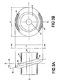
- FIG. 3A and 3B one of the cutters 14 of the embodiment in which a cutter blade 15 is elliptical is shown on an enlarged scale with respect to Figures 1 and 2 .
- the cutter 14 is mounted on a cutter hub 16.
- the hub 16 has a bore 18 for mounting the cutter and hub on the cutter head 10.
- the blade 15 defines a cutting edge 20 which lies In an imaginary plane.
- the angle oc between the planes of the cutting edge 20 and a center line 22 is 15 degrees.
- the imaginary plane of the cutting edge 20 when viewed In the plane of Figure 3A , Intersects the hub axis at approximately 75 degrees.
- the angle of that intersection is preferably in a range less than 90 degrees with the preferred angle being a variable depending on the type of the material being bored. It should be recognized that in a plane perpendicular to the hub axis and located by the center line of Figure 3A a radius of the cutter 15 is perpendicular to the hub axis.
- the blade is elliptical with the major axis of the ellipse being in a plane including the hub axis and a plane normal to the hub axis and intersecting the blade at its center.
- the minor axis is normal to the major axis and in a plane defined by the cutting edge of Figure 3A and bisecting the cutter.
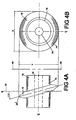
- the blade of Figures 4A and 4B is concentric In a plane bisecting the cutter which is the plane of the cutting edge 20'. In the drawings both embodiments are shown at 75 degrees with the hub axis.
- 75 degrees is the maximum angle of inclination of the cutting edge relative to the hub axis such that the points of contact of the cutting edge as the cutter is rotated produce an arc ranging from 75 degrees to one side of perpendicular to 75 degrees to the other side.
- the head and body 10, 12 are advanced until the cutters 14 are positioned to commence to engage the head wall to be bored.
- the head 10 is then caused to rotate about its axis while thrust, to the right as viewed in Figure 1 , is applied to force the cutters against a head wall being bored.
- cutters made In accordance with the present invention and having optimized skewing and eccentricity or concentricity for the material to be bored will be mounted In the boring head.
- an operator will determine the type of the material to be bored and use cutters which tests have shown to have optimized amounts of skewing and eccentricity.
Landscapes
- Engineering & Computer Science (AREA)
- Mining & Mineral Resources (AREA)
- Environmental & Geological Engineering (AREA)
- Life Sciences & Earth Sciences (AREA)
- General Life Sciences & Earth Sciences (AREA)
- Geochemistry & Mineralogy (AREA)
- Geology (AREA)
- Excavating Of Shafts Or Tunnels (AREA)
- Earth Drilling (AREA)
- Geophysics And Detection Of Objects (AREA)
- Lining And Supports For Tunnels (AREA)
- Medicines That Contain Protein Lipid Enzymes And Other Medicines (AREA)
Claims (11)
- Schneidvorrichtung zur Verwendung beim Bohren von Tunneln und dgl., mit:a) einer Nabe (16), die um eine Nabenachse herum angebracht und gedreht werden kann, undb) einer Schneidklinge (15), die von der Nabe (16) getragen wird,c) wobei die Schneidklinge (15) eine periphere Schneidkante (20) aufweist, die eine imaginäre Schneidebene definiert, undd) wobei die Schneidklinge (15) feststehend an der Nabe (16) zur Drehung um die Nabenachse angebracht ist,
dadurch gekennzeichnet, daße) die Schneidebene (α) von der Nabenachse unter einem anderen Winkel als einem senkrechten geschnitten wird. - Schneidvorrichtung nach Anspruch 1, wobei die Schneidkante (20) kreisförmig ist.
- Schneidvorrichtung nach Anspruch 1, wobei die Schneidkante (20) eine Ellipse ist.
- Schneidvorrichtung nach Anspruch 1, 2 oder 3, wobei die Nabenachse die Schneidebene (α) unter einem Winkel von etwa 75° schneidet.
- Schneidvorrichtung nach Anspruch 1, 2, 3 oder 4, wobei die Nabenachse die Schneidklinge (15) in ihrer Mitte schneidet.
- Tunnelbohrvorrichtung mit:a) einem Kopf (10) mit einer Schneidseite bzw. -fläche,b) wobei der Kopf (10) um eine Kopfachse herum drehbar ist und die Kopfachse quer zur Schneidfläche liegt,c) mehreren Schneidvorrichtungen (14) gemäß einem der Ansprüche 1 bis 5, von denen jede an dem Kopf (10) über ihre jeweilige Nabe (16) zur Drehung um ihre jeweilige Nabenachse angebracht ist, undd) wobei jede solche jeweilige Nabenachse in einer imaginären Ebene liegt, die eine andere imaginäre Ebene, welche die Kopfachse enthält, schneidet.
- Tunnelbohrvorrichtung nach Anspruch 6, wobei die Schneidklingen (15) und zugeordneten Naben (16) der Schneidvorrichtungen (14) im Einsatz durch Reibungseingriff der Schneidklingen (15) mit einer Stirnwand eines gerade gebohrten Tunnels in Drehung gebracht werden.
- Tunnelbohrvorrichtung nach Anspruch 7, wobei jede drehbar angebrachte Schneidklinge (15) mit einer solchen Tunnelstirnwand in einem Bogenkantenmuster ("scallop pattern") in Eingriff ist, wenn die Vorrichtung im Einsatz ist.
- Verfahren zum Bohren eines Tunnels mit auf einer Nabe angebrachten Schneidvorrichtungen, wie sie in einem der Ansprüche 1 bis 5 definiert sind, wobei das Verfahren umfasst:a) Montieren der Naben (16) in der Fläche eines Bohrkopfs (10) zur Drehung relativ zu dem Kopf,b) in Eingriff bringen der Schneidklingen (15) mit einer Tunnelstirnwand,c) Drehen des Kopfs (10) um eine Kopfachse, während gleichzeitig eine Schubkraft auf den Kopf aufgebracht wird, um zumindest einige der Schneidklingen (15) in Bohrkontakt mit der Tunnelstirnwand zu halten, undd) wobei die Kopfdrehung und der Zwangsvorschub zumindest einige der Schneidklingen (15) zur Drehung um jeweilige Nabenachsen bringt, wodurch die Schneidklingen (15) auf die Tunnelstirnwand in einer pulsierenden Aktion auftreffen.
- Verfahren nach Anspruch 9, wobei die Naben (16) so angebracht sind, dass sich ihre jeweiligen Nabenachsen in einer imaginären Ebene befinden, welche eine andere imaginäre Ebene, die die Kopfachse enthält, schneidet.
- Verfahren nach Anspruch 9 oder 10, wobei mindestens einige der Naben (16) so angebracht sind, dass sich ihre jeweiligen Nabenachsen in imaginären Ebenen normal zu der Kopfachse befinden.
Applications Claiming Priority (3)
| Application Number | Priority Date | Filing Date | Title |
|---|---|---|---|
| US356058 | 2003-01-31 | ||
| US10/356,058 US6857488B2 (en) | 2003-01-31 | 2003-01-31 | Boring head cutter |
| PCT/US2003/034660 WO2004070160A1 (en) | 2003-01-31 | 2003-10-31 | Tunnel boring apparatus |
Publications (3)
| Publication Number | Publication Date |
|---|---|
| EP1592860A1 EP1592860A1 (de) | 2005-11-09 |
| EP1592860A4 EP1592860A4 (de) | 2007-04-18 |
| EP1592860B1 true EP1592860B1 (de) | 2008-07-30 |
Family
ID=32770701
Family Applications (1)
| Application Number | Title | Priority Date | Filing Date |
|---|---|---|---|
| EP03778015A Expired - Lifetime EP1592860B1 (de) | 2003-01-31 | 2003-10-31 | Tunnelbohrvorrichtung |
Country Status (6)
| Country | Link |
|---|---|
| US (1) | US6857488B2 (de) |
| EP (1) | EP1592860B1 (de) |
| AT (1) | ATE403065T1 (de) |
| AU (1) | AU2003286801A1 (de) |
| DE (1) | DE60322594D1 (de) |
| WO (1) | WO2004070160A1 (de) |
Families Citing this family (3)
| Publication number | Priority date | Publication date | Assignee | Title |
|---|---|---|---|---|
| CA2651966C (en) * | 2006-05-12 | 2011-08-23 | Weatherford/Lamb, Inc. | Stage cementing methods used in casing while drilling |
| WO2009042189A2 (en) * | 2007-09-25 | 2009-04-02 | Caterpillar Inc. | Rotary cutter for tunnel boring machine |
| US9464487B1 (en) | 2015-07-22 | 2016-10-11 | William Harrison Zurn | Drill bit and cylinder body device, assemblies, systems and methods |
Family Cites Families (23)
| Publication number | Priority date | Publication date | Assignee | Title |
|---|---|---|---|---|
| US17660A (en) | 1857-06-30 | Machine fob making bolts and rivets | ||
| US1320144A (en) | 1919-10-28 | hencken | ||
| US2234197A (en) | 1938-12-13 | 1941-03-11 | Chicago Pneumatic Tool Co | Earth boring apparatus |
| US3041055A (en) | 1959-07-13 | 1962-06-26 | Goodman Mfg Co | Rotatable cutter head |
| US3598445A (en) * | 1969-05-08 | 1971-08-10 | Douglas F Winberg | Tunnel-boring machine |
| US4161225A (en) * | 1977-12-07 | 1979-07-17 | Dresser Industries, Inc. | Skewed inserts for an earth boring cutter |
| US4189186A (en) * | 1978-06-12 | 1980-02-19 | Jarva, Inc. | Tunneling machine |
| US4202419A (en) | 1979-01-11 | 1980-05-13 | Dresser Industries, Inc. | Roller cutter with major and minor insert rows |
| SE463110B (sv) | 1979-02-02 | 1990-10-08 | Sandvik Ab | Saett och anordning foer stigortsdrivning |
| US4371211A (en) * | 1980-12-11 | 1983-02-01 | Jarva, Inc. | Tunnel boring machine and method of operating same |
| US4393949A (en) | 1980-12-29 | 1983-07-19 | Peterson Associates, Ltd. | Rock boring apparatus |
| CH653742A5 (en) * | 1981-06-17 | 1986-01-15 | Hannelore Bechem | Unit for drilling rock, with a drilling head having percussive, radially vibrating drilling tools |
| US4549614A (en) | 1981-08-07 | 1985-10-29 | Engtech Sa | Drilling device |
| US4751972A (en) | 1986-03-13 | 1988-06-21 | Smith International, Inc. | Revolving cutters for rock bits |
| US4762188A (en) | 1987-02-09 | 1988-08-09 | Roger Masse | Drill bit |
| US5125719A (en) * | 1991-03-29 | 1992-06-30 | Larry Snyder | Tunnel boring machine and method |
| US5626201A (en) * | 1993-09-20 | 1997-05-06 | Excavation Engineering Associates, Inc. | Disc cutter and method of replacing disc cutters |
| US5421422A (en) * | 1993-11-19 | 1995-06-06 | Boretec Inc | Roller cutter mount for tunneling machine |
| US5456328A (en) | 1994-01-07 | 1995-10-10 | Dresser Industries, Inc. | Drill bit with improved rolling cutter tooth pattern |
| US5598895A (en) | 1995-01-19 | 1997-02-04 | Atlas Copco Robbins Inc. | Cutter assembly having a plurality of independently rotatable cutting units thereon |
| GB2309043B (en) * | 1996-01-13 | 1999-06-23 | Andaray Eng Ltd | Improvements relating to tunnel-boring machines |
| JP2000213284A (ja) * | 1999-01-26 | 2000-08-02 | Shimizu Corp | トンネル掘削機及びロ―ラ―カッタ |
| AUPP846599A0 (en) * | 1999-02-04 | 1999-02-25 | Sugden, David Burnet | Cutting device |
-
2003
- 2003-01-31 US US10/356,058 patent/US6857488B2/en not_active Expired - Fee Related
- 2003-10-31 AT AT03778015T patent/ATE403065T1/de not_active IP Right Cessation
- 2003-10-31 EP EP03778015A patent/EP1592860B1/de not_active Expired - Lifetime
- 2003-10-31 AU AU2003286801A patent/AU2003286801A1/en not_active Abandoned
- 2003-10-31 WO PCT/US2003/034660 patent/WO2004070160A1/en not_active Ceased
- 2003-10-31 DE DE60322594T patent/DE60322594D1/de not_active Expired - Lifetime
Also Published As
| Publication number | Publication date |
|---|---|
| WO2004070160A1 (en) | 2004-08-19 |
| EP1592860A1 (de) | 2005-11-09 |
| EP1592860A4 (de) | 2007-04-18 |
| DE60322594D1 (de) | 2008-09-11 |
| US20040150257A1 (en) | 2004-08-05 |
| AU2003286801A1 (en) | 2004-08-30 |
| ATE403065T1 (de) | 2008-08-15 |
| US6857488B2 (en) | 2005-02-22 |
Similar Documents
| Publication | Publication Date | Title |
|---|---|---|
| AU2020277282B2 (en) | Cutter head for mining machine | |
| US4342368A (en) | Rotary drills and drill bits | |
| US4550791A (en) | Two-prong rotary bit, especially for use with roof drills, and insert therefor | |
| CA1172885A (en) | Milling tool for forming recesses in masonry, concrete and similar material structures | |
| CN108468548B (zh) | 一种环形剪刀型盾构机刀盘装置 | |
| US4755004A (en) | Rotary rocksaw device | |
| JPH04228796A (ja) | 削岩ドリル | |
| US6857488B2 (en) | Boring head cutter | |
| CN110905542A (zh) | 一种适用于柔臂掘进机的tbm刀盘及其开挖方法 | |
| CN212376660U (zh) | 一种带有可伸缩地质钻的盾构机刀盘结构 | |
| US5662387A (en) | Cutter head and method for mining hard rock | |
| CN112832798A (zh) | 一种分块控制的顶管机刀盘 | |
| CN108368740A (zh) | 用于挖掘采矿材料的研磨装置 | |
| US3288532A (en) | Continuous mining machine and method | |
| US4393949A (en) | Rock boring apparatus | |
| CN211201980U (zh) | 一种适用于柔臂掘进机的tbm刀盘 | |
| GB2149329A (en) | A two-prong rotary bit, especially for use with roof drills, and insert therefor | |
| KR102730778B1 (ko) | 암맥 절단형 무진동 할암 작업 공법 및 상기 암맥 절단형 무진동 할암 작업 공법에 적용되는 암맥 절단형 무진동 할암 작업용 저소음 착암기 | |
| JPS6198897A (ja) | 脆性物体の破砕方法およびその装置 | |
| RU2149995C1 (ru) | Шнековый исполнительный орган | |
| US20240247587A1 (en) | Cutting device and support for same | |
| CN121205512B (zh) | 一种基岩出露地层半航空瞬变电磁勘探用电极孔钻具 | |
| RU2212510C2 (ru) | Резец для бурения шпуров | |
| SU960415A1 (ru) | Устройство дл расширени восстающих скважин в крепких породах | |
| US2939690A (en) | Rotary cutting head having core burster means |
Legal Events
| Date | Code | Title | Description |
|---|---|---|---|
| PUAI | Public reference made under article 153(3) epc to a published international application that has entered the european phase |
Free format text: ORIGINAL CODE: 0009012 |
|
| 17P | Request for examination filed |
Effective date: 20050819 |
|
| AK | Designated contracting states |
Kind code of ref document: A1 Designated state(s): AT BE BG CH CY CZ DE DK EE ES FI FR GB GR HU IE IT LI LU MC NL PT RO SE SI SK TR |
|
| AX | Request for extension of the european patent |
Extension state: AL LT LV MK |
|
| DAX | Request for extension of the european patent (deleted) | ||
| A4 | Supplementary search report drawn up and despatched |
Effective date: 20070316 |
|
| RIC1 | Information provided on ipc code assigned before grant |
Ipc: E21D 9/11 20060101AFI20070312BHEP |
|
| 17Q | First examination report despatched |
Effective date: 20070710 |
|
| GRAP | Despatch of communication of intention to grant a patent |
Free format text: ORIGINAL CODE: EPIDOSNIGR1 |
|
| GRAS | Grant fee paid |
Free format text: ORIGINAL CODE: EPIDOSNIGR3 |
|
| GRAA | (expected) grant |
Free format text: ORIGINAL CODE: 0009210 |
|
| AK | Designated contracting states |
Kind code of ref document: B1 Designated state(s): AT BE BG CH CY CZ DE DK EE ES FI FR GB GR HU IE IT LI LU MC NL PT RO SE SI SK TR |
|
| REG | Reference to a national code |
Ref country code: GB Ref legal event code: FG4D |
|
| REG | Reference to a national code |
Ref country code: CH Ref legal event code: EP |
|
| REF | Corresponds to: |
Ref document number: 60322594 Country of ref document: DE Date of ref document: 20080911 Kind code of ref document: P |
|
| REG | Reference to a national code |
Ref country code: IE Ref legal event code: FG4D |
|
| PG25 | Lapsed in a contracting state [announced via postgrant information from national office to epo] |
Ref country code: ES Free format text: LAPSE BECAUSE OF FAILURE TO SUBMIT A TRANSLATION OF THE DESCRIPTION OR TO PAY THE FEE WITHIN THE PRESCRIBED TIME-LIMIT Effective date: 20081110 Ref country code: NL Free format text: LAPSE BECAUSE OF FAILURE TO SUBMIT A TRANSLATION OF THE DESCRIPTION OR TO PAY THE FEE WITHIN THE PRESCRIBED TIME-LIMIT Effective date: 20080730 Ref country code: PT Free format text: LAPSE BECAUSE OF FAILURE TO SUBMIT A TRANSLATION OF THE DESCRIPTION OR TO PAY THE FEE WITHIN THE PRESCRIBED TIME-LIMIT Effective date: 20081230 |
|
| PG25 | Lapsed in a contracting state [announced via postgrant information from national office to epo] |
Ref country code: SI Free format text: LAPSE BECAUSE OF FAILURE TO SUBMIT A TRANSLATION OF THE DESCRIPTION OR TO PAY THE FEE WITHIN THE PRESCRIBED TIME-LIMIT Effective date: 20080730 Ref country code: BG Free format text: LAPSE BECAUSE OF FAILURE TO SUBMIT A TRANSLATION OF THE DESCRIPTION OR TO PAY THE FEE WITHIN THE PRESCRIBED TIME-LIMIT Effective date: 20081030 Ref country code: FI Free format text: LAPSE BECAUSE OF FAILURE TO SUBMIT A TRANSLATION OF THE DESCRIPTION OR TO PAY THE FEE WITHIN THE PRESCRIBED TIME-LIMIT Effective date: 20080730 Ref country code: AT Free format text: LAPSE BECAUSE OF FAILURE TO SUBMIT A TRANSLATION OF THE DESCRIPTION OR TO PAY THE FEE WITHIN THE PRESCRIBED TIME-LIMIT Effective date: 20080730 |
|
| PG25 | Lapsed in a contracting state [announced via postgrant information from national office to epo] |
Ref country code: BE Free format text: LAPSE BECAUSE OF FAILURE TO SUBMIT A TRANSLATION OF THE DESCRIPTION OR TO PAY THE FEE WITHIN THE PRESCRIBED TIME-LIMIT Effective date: 20080730 |
|
| PGFP | Annual fee paid to national office [announced via postgrant information from national office to epo] |
Ref country code: IT Payment date: 20081028 Year of fee payment: 6 |
|
| PG25 | Lapsed in a contracting state [announced via postgrant information from national office to epo] |
Ref country code: EE Free format text: LAPSE BECAUSE OF FAILURE TO SUBMIT A TRANSLATION OF THE DESCRIPTION OR TO PAY THE FEE WITHIN THE PRESCRIBED TIME-LIMIT Effective date: 20080730 Ref country code: DK Free format text: LAPSE BECAUSE OF FAILURE TO SUBMIT A TRANSLATION OF THE DESCRIPTION OR TO PAY THE FEE WITHIN THE PRESCRIBED TIME-LIMIT Effective date: 20080730 |
|
| PG25 | Lapsed in a contracting state [announced via postgrant information from national office to epo] |
Ref country code: RO Free format text: LAPSE BECAUSE OF FAILURE TO SUBMIT A TRANSLATION OF THE DESCRIPTION OR TO PAY THE FEE WITHIN THE PRESCRIBED TIME-LIMIT Effective date: 20080730 Ref country code: SK Free format text: LAPSE BECAUSE OF FAILURE TO SUBMIT A TRANSLATION OF THE DESCRIPTION OR TO PAY THE FEE WITHIN THE PRESCRIBED TIME-LIMIT Effective date: 20080730 Ref country code: CZ Free format text: LAPSE BECAUSE OF FAILURE TO SUBMIT A TRANSLATION OF THE DESCRIPTION OR TO PAY THE FEE WITHIN THE PRESCRIBED TIME-LIMIT Effective date: 20080730 Ref country code: MC Free format text: LAPSE BECAUSE OF NON-PAYMENT OF DUE FEES Effective date: 20081031 |
|
| REG | Reference to a national code |
Ref country code: CH Ref legal event code: PL |
|
| PLBE | No opposition filed within time limit |
Free format text: ORIGINAL CODE: 0009261 |
|
| STAA | Information on the status of an ep patent application or granted ep patent |
Free format text: STATUS: NO OPPOSITION FILED WITHIN TIME LIMIT |
|
| GBPC | Gb: european patent ceased through non-payment of renewal fee |
Effective date: 20081031 |
|
| 26N | No opposition filed |
Effective date: 20090506 |
|
| REG | Reference to a national code |
Ref country code: IE Ref legal event code: MM4A |
|
| REG | Reference to a national code |
Ref country code: FR Ref legal event code: ST Effective date: 20090630 |
|
| PG25 | Lapsed in a contracting state [announced via postgrant information from national office to epo] |
Ref country code: FR Free format text: LAPSE BECAUSE OF NON-PAYMENT OF DUE FEES Effective date: 20081031 Ref country code: LI Free format text: LAPSE BECAUSE OF NON-PAYMENT OF DUE FEES Effective date: 20081031 Ref country code: CH Free format text: LAPSE BECAUSE OF NON-PAYMENT OF DUE FEES Effective date: 20081031 Ref country code: IE Free format text: LAPSE BECAUSE OF NON-PAYMENT OF DUE FEES Effective date: 20081031 |
|
| PG25 | Lapsed in a contracting state [announced via postgrant information from national office to epo] |
Ref country code: GB Free format text: LAPSE BECAUSE OF NON-PAYMENT OF DUE FEES Effective date: 20081031 |
|
| PG25 | Lapsed in a contracting state [announced via postgrant information from national office to epo] |
Ref country code: SE Free format text: LAPSE BECAUSE OF FAILURE TO SUBMIT A TRANSLATION OF THE DESCRIPTION OR TO PAY THE FEE WITHIN THE PRESCRIBED TIME-LIMIT Effective date: 20081030 |
|
| PG25 | Lapsed in a contracting state [announced via postgrant information from national office to epo] |
Ref country code: LU Free format text: LAPSE BECAUSE OF NON-PAYMENT OF DUE FEES Effective date: 20081031 Ref country code: HU Free format text: LAPSE BECAUSE OF FAILURE TO SUBMIT A TRANSLATION OF THE DESCRIPTION OR TO PAY THE FEE WITHIN THE PRESCRIBED TIME-LIMIT Effective date: 20090131 Ref country code: CY Free format text: LAPSE BECAUSE OF FAILURE TO SUBMIT A TRANSLATION OF THE DESCRIPTION OR TO PAY THE FEE WITHIN THE PRESCRIBED TIME-LIMIT Effective date: 20080730 |
|
| PG25 | Lapsed in a contracting state [announced via postgrant information from national office to epo] |
Ref country code: TR Free format text: LAPSE BECAUSE OF FAILURE TO SUBMIT A TRANSLATION OF THE DESCRIPTION OR TO PAY THE FEE WITHIN THE PRESCRIBED TIME-LIMIT Effective date: 20080730 |
|
| PG25 | Lapsed in a contracting state [announced via postgrant information from national office to epo] |
Ref country code: GR Free format text: LAPSE BECAUSE OF FAILURE TO SUBMIT A TRANSLATION OF THE DESCRIPTION OR TO PAY THE FEE WITHIN THE PRESCRIBED TIME-LIMIT Effective date: 20081031 |
|
| PG25 | Lapsed in a contracting state [announced via postgrant information from national office to epo] |
Ref country code: IT Free format text: LAPSE BECAUSE OF NON-PAYMENT OF DUE FEES Effective date: 20091031 |
|
| PGFP | Annual fee paid to national office [announced via postgrant information from national office to epo] |
Ref country code: DE Payment date: 20121228 Year of fee payment: 10 |
|
| REG | Reference to a national code |
Ref country code: DE Ref legal event code: R119 Ref document number: 60322594 Country of ref document: DE Effective date: 20140501 |
|
| PG25 | Lapsed in a contracting state [announced via postgrant information from national office to epo] |
Ref country code: DE Free format text: LAPSE BECAUSE OF NON-PAYMENT OF DUE FEES Effective date: 20140501 |