EP1593503A2 - Dispostif de guidage du film d'une machine de dorure à plat - Google Patents
Dispostif de guidage du film d'une machine de dorure à plat Download PDFInfo
- Publication number
- EP1593503A2 EP1593503A2 EP05405324A EP05405324A EP1593503A2 EP 1593503 A2 EP1593503 A2 EP 1593503A2 EP 05405324 A EP05405324 A EP 05405324A EP 05405324 A EP05405324 A EP 05405324A EP 1593503 A2 EP1593503 A2 EP 1593503A2
- Authority
- EP
- European Patent Office
- Prior art keywords
- film
- film web
- web guide
- embossing
- guide according
- Prior art date
- Legal status (The legal status is an assumption and is not a legal conclusion. Google has not performed a legal analysis and makes no representation as to the accuracy of the status listed.)
- Granted
Links
Images


Classifications
-
- B—PERFORMING OPERATIONS; TRANSPORTING
- B41—PRINTING; LINING MACHINES; TYPEWRITERS; STAMPS
- B41F—PRINTING MACHINES OR PRESSES
- B41F19/00—Apparatus or machines for carrying out printing operations combined with other operations
- B41F19/02—Apparatus or machines for carrying out printing operations combined with other operations with embossing
- B41F19/06—Printing and embossing between a negative and a positive forme after inking and wiping the negative forme; Printing from an ink band treated with colour or "gold"
- B41F19/064—Presses of the reciprocating type
- B41F19/068—Presses of the reciprocating type motor-driven
-
- B—PERFORMING OPERATIONS; TRANSPORTING
- B41—PRINTING; LINING MACHINES; TYPEWRITERS; STAMPS
- B41P—INDEXING SCHEME RELATING TO PRINTING, LINING MACHINES, TYPEWRITERS, AND TO STAMPS
- B41P2219/00—Printing presses using a heated printing foil
- B41P2219/20—Arrangements for moving, supporting or positioning the printing foil
- B41P2219/21—Supports for the unwinding roll; Braking devices for the unwinding roll
-
- B—PERFORMING OPERATIONS; TRANSPORTING
- B41—PRINTING; LINING MACHINES; TYPEWRITERS; STAMPS
- B41P—INDEXING SCHEME RELATING TO PRINTING, LINING MACHINES, TYPEWRITERS, AND TO STAMPS
- B41P2219/00—Printing presses using a heated printing foil
- B41P2219/20—Arrangements for moving, supporting or positioning the printing foil
- B41P2219/22—Guiding or tensioning the printing foil
Definitions
- the invention relates to a film web guide for a flat embossing machine with film webs, which are guided by unwinding rollers on an embossing table according to the preamble of claim 1.
- flat embossing machines particularly high embossing performances in the best quality and for particularly demanding embossing tasks such as relief embossing can be performed.
- these flat embossing machines also place particularly high demands on the guidance and precise preference of the thin and very sensitive embossed foil webs, with layer thicknesses of, for example, only 12-20 ⁇ m (0.02 mm).
- the film web guide has before the embossing table to a tensioning roller, in which necessarily two deflection rollers on the embossing layer side of the film webs are required, which can affect the sensitive embossing layer. Moreover, the tensile stresses for several film webs are limited and relatively complex individually adjustable here. The necessary set-up and changeover times for several film webs are still relatively high.
- This object is achieved according to the invention by a film web guide for a flat embossing printing machine with at least one flat braking and guide wall as film tensioning device in front of the embossing table according to claim 1.
- the dependent claims relate to advantageous developments of the invention with further improvements of the film web guide and thus also the machine performance as well as with respect to the shortening of set-up and changeover times.
- Fig. 1 shows an inventive film web guide 2 for a flat embossing machine 1 with a flatbed press 4, wherein film webs 6 of unwinding rollers. 7 be led to an embossing table 3 for embossing flat material 5.
- Das Sheet 5 may consist of paper sheets or paper webs from rolls. The sheet is moved in the machine longitudinal direction X. In addition, you can also film webs in the transverse direction Y are drawn onto the embossing table 3 (Fig. 8).
- the film web guide 2 has a film tensioning device in front of the embossing table and Film feed devices 9.1, 9.2 for several film webs 6.1, 6.2 after the Embossing table 3 on.
- a flat brake and guide wall 10 is provided as a film tensioning device, over which the film webs 6 are guided.
- This brake and Guide walls 10 have a solid support layer 11 which a support and Guide surface forms, with suction openings 14 and a lying on the Carrier layer 11 fixed, cloth-like, air-permeable support layer 12 and a associated, adjustable negative pressure source 13, wherein in a flat vacuum chamber 17 a negative pressure dp is generated. So the film webs are easy on pressed the support layer and thus guided and braked adjustable.
- the flat brake and guide walls 10 may also be slightly bent and thus additionally result in a deflection of the film webs 6 (in FIG Brake and guide wall 10.1 a slight bend in the direction of embossing point. 3 exhibit).
- the structure and operation of the brake and guide walls 10th are further explained to Figs. 2-4.
- a braking and guide wall 10.1 is arranged directly in front of the embossing table 3 with which for each film web 6.1, 6.2 individually set an optimal tension for the embossing process, so that in particular all film webs 6 again solved properly after embossing of the embossed sheet 5 and can be dissipated.
- the required release stresses depend on the type and dimension of the film webs and the embossing process (different embossing surfaces and embossing, eg relief embossing).
- Fig. 1 On the long path of the film web guide 2 from the unwinding rollers 7 to the Embossing table 3 can also be arranged more than one braking and guiding wall 10 become.
- Fig. 1 is an additional brake and guide wall 10.2 mounted shortly after a film storage 20.
- the foil stores are here as Vacuum loop storage, especially as a horizontal vacuum double-loop storage 20 formed and in the film web feed, i. in front of the embossing table 3, arranged.
- the vacuum loop memory 20 By the vacuum loop memory 20 is a first tension Z1 generated in the film webs 6.
- a vacuum blower 21 of the loop memory 20 can be used here as a vacuum source 13.
- the negative pressure dp2 in a vacuum chamber 17 can be additionally adjusted, for example by means of a variable throttle point 19.
- the usually relatively moderate additional tensile stress Z2, which is generated by this braking and guide wall 10.2, is adjusted so that a properly stretched film web guide is achieved until the next brake and guide wall 10.1.
- the additional tensile stresses Z3 (see FIG. 4) on the braking and guide wall 10.1 can be set individually for each film web 6.1, 6.2, 6.3 in such a way that optimum positioning on the embossment 3 and proper detachment of the film webs 6 from the embossed flat material 5 is achieved after embossing.
- the film web guide has a film removal device 29 downstream of the film feed devices 9.1, 9.2 for the lateral removal of the distinct film webs 6.1, 6.2.
- the adjustment of the braking forces or the tensile stresses in the film webs on the vacuum loop memory (Z1) and on the braking and guide walls (Z2, Z3) can be coordinated so that the detachment of the film webs from the embossed sheet 5 after embossing and the film web guide over the whole length is flawless and optimized.
- a total tension Z Z1 + Z2 + Z3 generated. Due to the forced, precisely positioned and very rapid film preference by means of the film feed devices 9.1, 9.2, a tensile stress Z4 is generated, which must correspond to at least the total tensile stress Z.
- the stress of the pronounced film webs on the film feed devices 9 with deflecting rollers, which must necessarily also touch the stamping page 6a of the film webs, is substantially higher than on the flat braking and guide walls 10, where no guide elements and no contact on the stamping page 6a are required.
- the embossing page 6a is not contacted all the way from the unwinding rollers 7 to the embossing table 3.
- the required negative pressure dp at the large-area brake and guide walls 10 is correspondingly relatively small and is for example 500 - 2000 Pa and the generated total tensile stress Z in the very thin film webs 6 is for example as possible less than 5 N / cm film web width.
- the positioned film webs 6 on the embossing table 3 before stamping by short Reversing the film feed devices 9 partially relaxed, then embossed and then pulled away again with full tensile stress Z. and thereby detached from the embossed sheet 5 with high tension become.
- the film feed devices 9 can be used e.g. by 2 - 5 mm backwards drive and thereby reduce the tensile stress Z during the embossing.
- Figs. 2a and 2b illustrate the structure and operation of the brake and Fig. 2a shows in cross section a brake and guide wall 10th with a solid support layer 11 (which forms a support and guide surface) with Suction openings 14 and a flat vacuum chamber 17, in which a Vacuum dp is generated by means of an adjustable vacuum source 13.
- a solid support layer 11 which forms a support and guide surface
- Suction openings 14 and a flat vacuum chamber 17, in which a Vacuum dp is generated by means of an adjustable vacuum source 13.
- On the Carrier layer 11 is a cloth-like, air-permeable support layer 12 is attached and fixed, e.g. clamped all around.
- the overlay layer is mainly in tangential direction 18 permeable to air, so that the negative pressure dp under a over ongoing film web 6 balanced or uniform over the surface is distributed.
- the film webs are thus uniform and relatively low Pressed contact pressure on the large-scale support layer 12, thereby braked and uniform and constant in the preferred direction or direction of movement v of Led film webs.
- the overlay layer 12 consists of a non-electrostatic rechargeable soft material, so no electrostatic friction forces can arise between the film web and support layer.
- the overlay layer 12 can be made of natural fibers such as cotton (with a minimal electrical Conductivity) and as a nonwoven fabric or as a textile structure such as tissue, Knitted or crocheted or as felt and with intermediate spaces, so that a desired tangential air permeability (18) is generated. With this Pad layer 12 can achieve a substantially constant coefficient of friction be, with static friction and sliding friction barely differ.
- this overlay layer 12 may be e.g. 0.3-1 mm; ever depending on the type and geometry of the wings and the overlay layer whose thickness also more, e.g. to 3 mm.
- This overlay can be easily interchangeable be attached to the carrier layer 11 and thus to adapt to the nature of Film webs also be easily replaced.
- FIG. 2b shows a plan view of an example of a preferably metallic carrier layer 11 with suction openings 14, which has an open surface portion of preferably 30 - 60% of the entire surface of the braking and guiding wall 10 form and which has an average diameter of e.g. 1 - 5 mm.
- Fig. 2b shows an advantageous embodiment of the carrier layer 11 as a slot wall with Slits which extend parallel to the preferred direction v of the film webs 6 and which allow a particularly good leadership.
- the slot width as well as the Distance between the slots may e.g. 1 - 3 mm and the slot length e.g. 10 - 30 mm.
- Other forms of the suction openings 14 are possible, e.g. as a perforated plate with a small hole diameter, so that the film webs 6 in essentially flat over it.
- Fig. 3 shows an example of a braking and guide wall 10 in section along the Film movement direction v with a length L, which is at least 20 cm, preferably rather more, e.g. 30 - 50 cm.
- Fig. 3 also illustrates the very flat Construction of the brake and guide walls 10 along the film web 6, whereby in Compared to previous clamping and guiding devices much less Space is needed, which is e.g. for additional unwinding rolls (7.3 in Fig. 1) Creates space.
- Fig. 4 shows an example of a braking and guiding wall 10 with three running over it Film webs 6.1, 6.2, 6.3 and with air-impermeable covers 15.1, 15.2 under a part of the film webs, so that only the uncovered part L1, L2, L3 of length L is exhausted and corresponding proportional braking forces or tensile stresses Z3.1, Z3.2, Z3.3 are generated in the film webs.
- the desired optimum braking force or Tensile Zi can thus here for each foil web individually - and practically between 0 and 100% - very easy to set.
- airtight covers 16 can be attached to here to avoid a pressure drop or a pressure loss and to set an optimal uniform distribution of the negative pressure dp at the brake and guide wall 10.
- the air-impermeable covers 15 and 16 can for example be cut very easily from paper sheets and fixed to the front edge 10a of the brake and guide wall.
- the brake and guide walls i. the carrier layers 11 with the support layers 12, are preferably formed easily replaceable or insertable. So they can be easily removed, the covers 15, 16 on it new set and the layers 11 and 12 are used again, without the film webs to move or to set up new ones. That is possible because of the Brake and guide walls 10 no pulleys on the recuperge fürseite 6a the film webs are present and needed.
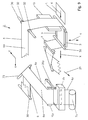
- Figs. 5 and 6 show examples of drawer cassettes 22 for vacuum loop storage 20, which are shown in Fig. 1.
- Fig. 5 shows a perspective Representation and Fig. 6 in plan a division with partitions and End walls of a slide-in cassette 22.
- a film web guide 2 with brake and Guide walls 10 and combined with vacuum loops 20 enables a particularly good film web guidance and conveying.
- removable Insertion cassettes 22 are inserted into the vacuum loop memories 20.
- adjustable partitions 23 are fixed so that the desired film webs are separated.
- the intermediate walls 23 are closed at the bottom by end walls 24, which separated, not aspirated Chambers 26 between and adjacent to the film webs 6.1, 6.2 in the film loop storage 20 are formed.
- end walls 24 which separated, not aspirated Chambers 26 between and adjacent to the film webs 6.1, 6.2 in the film loop storage 20 are formed.
- the inventive braking and guide walls 10 in flatbed embossing machines and the drawer cassettes 22 in the vacuum loop memories 20 allow much shorter set-up and changeover times, improved Film web guidance, higher embossing performances and an extended range of Embossing tasks. With ventilated deflection rods can be further improvements be achieved.
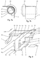
- FIGS. 7a, 7b show a deflecting element 27 for deflecting the film webs 6 in FIG Form of a standing ventilated deflection bar 30, which is an air cushion under the Sheets 6 generated so that they are deflected with minimal friction.
- a standing ventilated deflection bar 30 which is an air cushion under the Sheets 6 generated so that they are deflected with minimal friction.
- side guide elements 32 the film web on the air cushion can be very be exactly guided and stabilized. This results in comparison to previous ones Deflection elements 27, e.g. in the form of roller axes, minimal frictional forces and a better guidance of the film web.
- all deflecting elements can be designed as ventilated deflection rods become.
- the side guide members 32 may be e.g. as slip-on elements (clips) be made of Delrin and simply attached to the standing Umlenkstange 30 and also moved and adjusted.
- the vented deflection rods 30 can e.g. from a slightly positive pressure ventilated tube with a microporous Layer 31 exist which a finely distributed air cushion under the film web. 6 generated. This air cushion must be generated only in the deflection 34.
- the inventive film web guide with braking and guide walls 10 and with ventilated deflection rods or air cushion axes 30 also allows the Film web guide by means of ventilated 90 ° -Umlenkstangen 33 from the machine direction X in the transverse direction Y or vice versa from the transverse direction Y in the Redirecting the longitudinal direction X, as shown in Fig. 8 and 9 is shown.
- Slide benefits with Unwinding rollers in the longitudinal direction X and in the transverse direction Y are known and e.g. in EP 0 858 888.
- Fig. 8 shows an example with a film advantage 6y in the transverse direction Y with a Brake wall 10y in the transverse direction Y and with ventilated deflection rods 30 with Side guide elements 32 before and after the embossing 3. This is especially advantageous because the film web 6y after the embossing of the machine in the longitudinal direction X moving sheet 5 must be replaced transversely to and should not be moved.
- the unwinding roll 7 and the vacuum loop stores 20 form here a film preference in the longitudinal direction X.
- Fig. 9 shows film advantages in the transverse direction Y with unwinding rollers 7y and loop memories 20y in the transverse direction by means of a vented 90 ° -Umlenkstange 33.
- a splice device 35 which between the unwinding rollers 7 and the vacuum loop memory 10 is arranged (Fig. 1).
Landscapes
- Advancing Webs (AREA)
- Registering, Tensioning, Guiding Webs, And Rollers Therefor (AREA)
Applications Claiming Priority (2)
| Application Number | Priority Date | Filing Date | Title |
|---|---|---|---|
| CH7892004 | 2004-05-04 | ||
| CH7892004 | 2004-05-04 |
Publications (3)
| Publication Number | Publication Date |
|---|---|
| EP1593503A2 true EP1593503A2 (fr) | 2005-11-09 |
| EP1593503A3 EP1593503A3 (fr) | 2006-07-26 |
| EP1593503B1 EP1593503B1 (fr) | 2013-06-26 |
Family
ID=34942981
Family Applications (1)
| Application Number | Title | Priority Date | Filing Date |
|---|---|---|---|
| EP05405324.4A Expired - Lifetime EP1593503B1 (fr) | 2004-05-04 | 2005-04-29 | Dispostif de guidage du film d'une machine de dorure à plat |
Country Status (2)
| Country | Link |
|---|---|
| US (1) | US7424903B2 (fr) |
| EP (1) | EP1593503B1 (fr) |
Cited By (11)
| Publication number | Priority date | Publication date | Assignee | Title |
|---|---|---|---|---|
| DE102008011493A1 (de) * | 2008-02-20 | 2009-08-27 | Spm Steuer Gmbh & Co. Kg | Verfahren zur Entsorgung von verbrauchter Prägefolienbahn sowie Prägevorrichtung mit kontinuierlich arbeitender Entsorgungseinrichtung |
| EP2128060A2 (fr) | 2008-05-28 | 2009-12-02 | SPM Steuer GmbH & Co. KG | Machine d'estampage de feuilles |
| WO2009143644A1 (fr) * | 2008-05-27 | 2009-12-03 | Gietz Ag | Machine d'impression-gaufrage à plat pourvue d'un dispositif de guidage de feuilles continues |
| WO2012034649A1 (fr) * | 2010-09-16 | 2012-03-22 | Bobst Sa | Dispositif de guidage de bandes pour machine d'estampage |
| CN103097135A (zh) * | 2010-09-08 | 2013-05-08 | 鲍勃斯脱梅克斯股份有限公司 | 向传送烫印箔的系统导入烫印箔的方法及其实施装置 |
| WO2016086325A1 (fr) | 2014-12-04 | 2016-06-09 | Gietz Ag | Machine d'impression par gaufrage avec guidage de bande de film et de feuille |
| EP3173232A1 (fr) | 2015-11-30 | 2017-05-31 | KBA-NotaSys SA | Presse à estamper à chaud |
| WO2019200596A1 (fr) * | 2018-04-20 | 2019-10-24 | Bobst Mex Sa | Dispositif d'entraînement d'une feuille d'estampage, station et machine d'estampage, et procédé de commande de l'entraînement d'une feuille d'estampage |
| US10737485B2 (en) | 2015-11-05 | 2020-08-11 | Kba-Notasys Sa | Sheet-fed stamping press comprising a foil laminating unit |
| US11065865B2 (en) | 2015-11-05 | 2021-07-20 | Kba-Notasys Sa | Sheet-fed stamping press having a foil laminating unit |
| WO2023148250A1 (fr) | 2022-02-02 | 2023-08-10 | Gietz Ag | Machine d'impression par estampage à plat comprenant un dispositif de guidage et de transport de bande de film |
Families Citing this family (11)
| Publication number | Priority date | Publication date | Assignee | Title |
|---|---|---|---|---|
| FR2913914B1 (fr) * | 2007-03-21 | 2012-09-07 | Cer | Machine de marquage a ruban |
| CN102896890A (zh) * | 2011-07-27 | 2013-01-30 | 上海亚华印刷机械有限公司 | 一种具备铝箔储存装置的烫印机 |
| CN103171921B (zh) * | 2013-03-20 | 2015-06-24 | 天津长荣印刷设备股份有限公司 | 一种收放膜缓冲装置及其工作方法 |
| CH711441A1 (de) | 2015-08-21 | 2017-02-28 | Gietz Ag | Flachprägedruckmaschine. |
| DE102017118927A1 (de) * | 2017-07-03 | 2019-01-03 | Weber Maschinenbau Gmbh Breidenbach | Bereitstellen von bahnförmigem Zwischenblattmaterial an einem Schneidbereich |
| DE102017118934A1 (de) * | 2017-07-03 | 2019-01-03 | Weber Maschinenbau Gmbh Breidenbach | Bereitstellen von bahnförmigem Zwischenblattmaterial an einem Schneidbereich |
| EP3888467A1 (fr) * | 2017-07-03 | 2021-10-06 | Weber Maschinenbau GmbH Breidenbach | Production de matériau intermédiaire sous forme de feuille en bande sur une zone de coupe |
| DE102017118925A1 (de) * | 2017-07-03 | 2019-01-03 | Weber Maschinenbau Gmbh Breidenbach | Bereitstellen von bahnförmigem Zwischenblattmaterial an einem Schneidbereich |
| EP3424852B1 (fr) * | 2017-07-03 | 2021-04-21 | Weber Maschinenbau GmbH Breidenbach | Fourniture de matériau de feuille intermédiaire en forme de bande à une zone de coupe |
| DE102017118930A1 (de) * | 2017-07-03 | 2019-01-03 | Weber Maschinenbau Gmbh Breidenbach | Bereitstellen von bahnförmigem Zwischenblattmaterial an einem Schneidbereich |
| CN110228288B (zh) * | 2018-03-05 | 2022-09-16 | 博斯特(上海)有限公司 | 吹气装置单元以及烫金模切设备 |
Citations (2)
| Publication number | Priority date | Publication date | Assignee | Title |
|---|---|---|---|---|
| DE601816C (de) | 1932-07-27 | 1934-08-25 | Jagenberg Werke Ag | Verfahren zum Auf- und Umwickeln von Papier |
| US4350310A (en) | 1979-12-12 | 1982-09-21 | Froehling Peter | Apparatus for braking travelling strip material |
Family Cites Families (2)
| Publication number | Priority date | Publication date | Assignee | Title |
|---|---|---|---|---|
| DE9420707U1 (de) * | 1994-12-24 | 1995-02-16 | Steuer, Armin, 71111 Waldenbuch | Präge-Rotationsmaschine |
| EP0858888B2 (fr) * | 1997-02-13 | 2007-03-07 | Maschinenfabrik Gietz Ag | Presse d'estampage à plat |
-
2005
- 2005-04-29 EP EP05405324.4A patent/EP1593503B1/fr not_active Expired - Lifetime
- 2005-05-03 US US11/121,265 patent/US7424903B2/en active Active
Patent Citations (2)
| Publication number | Priority date | Publication date | Assignee | Title |
|---|---|---|---|---|
| DE601816C (de) | 1932-07-27 | 1934-08-25 | Jagenberg Werke Ag | Verfahren zum Auf- und Umwickeln von Papier |
| US4350310A (en) | 1979-12-12 | 1982-09-21 | Froehling Peter | Apparatus for braking travelling strip material |
Cited By (26)
| Publication number | Priority date | Publication date | Assignee | Title |
|---|---|---|---|---|
| DE102008011493A1 (de) * | 2008-02-20 | 2009-08-27 | Spm Steuer Gmbh & Co. Kg | Verfahren zur Entsorgung von verbrauchter Prägefolienbahn sowie Prägevorrichtung mit kontinuierlich arbeitender Entsorgungseinrichtung |
| WO2009143644A1 (fr) * | 2008-05-27 | 2009-12-03 | Gietz Ag | Machine d'impression-gaufrage à plat pourvue d'un dispositif de guidage de feuilles continues |
| CN101868414A (zh) * | 2008-05-27 | 2010-10-20 | 吉茨公司 | 包括箔条引导装置的平面烫印机 |
| CN101868414B (zh) * | 2008-05-27 | 2013-09-11 | 吉茨公司 | 包括箔条引导装置的平面烫印机 |
| EP2128060A2 (fr) | 2008-05-28 | 2009-12-02 | SPM Steuer GmbH & Co. KG | Machine d'estampage de feuilles |
| DE102008026983A1 (de) * | 2008-05-28 | 2009-12-03 | Spm Steuer Gmbh & Co. Kg | Folienprägemaschine |
| EP2128060A3 (fr) * | 2008-05-28 | 2010-11-10 | SPM Steuer GmbH & Co. KG | Machine d'estampage de feuilles |
| KR101459251B1 (ko) * | 2010-09-08 | 2014-11-07 | 봅스트 맥스 에스에이 | 스트립을 이동시키는 시스템 내에서 엠보싱될 스트립을 공급하는 방법 및 이러한 방법을 실행하는 장치 |
| CN103097135A (zh) * | 2010-09-08 | 2013-05-08 | 鲍勃斯脱梅克斯股份有限公司 | 向传送烫印箔的系统导入烫印箔的方法及其实施装置 |
| CN103097135B (zh) * | 2010-09-08 | 2016-01-20 | 鲍勃斯脱梅克斯股份有限公司 | 向传送烫印箔的系统导入烫印箔的方法及其实施装置 |
| WO2012034649A1 (fr) * | 2010-09-16 | 2012-03-22 | Bobst Sa | Dispositif de guidage de bandes pour machine d'estampage |
| JP2013544197A (ja) * | 2010-09-16 | 2013-12-12 | ボブスト メックス ソシエテ アノニム | 箔押機械のためのストリップを案内するための装置 |
| CN103097136B (zh) * | 2010-09-16 | 2015-04-08 | 鲍勃斯脱梅克斯股份有限公司 | 用于烫印机的箔材导向装置 |
| CN103097136A (zh) * | 2010-09-16 | 2013-05-08 | 鲍勃斯脱梅克斯股份有限公司 | 用于烫印机的箔材导向装置 |
| US8839719B2 (en) | 2010-09-16 | 2014-09-23 | Bobst Mex Sa | Foil guiding device for stamping machine |
| WO2016086325A1 (fr) | 2014-12-04 | 2016-06-09 | Gietz Ag | Machine d'impression par gaufrage avec guidage de bande de film et de feuille |
| US10737485B2 (en) | 2015-11-05 | 2020-08-11 | Kba-Notasys Sa | Sheet-fed stamping press comprising a foil laminating unit |
| US11065865B2 (en) | 2015-11-05 | 2021-07-20 | Kba-Notasys Sa | Sheet-fed stamping press having a foil laminating unit |
| WO2017093894A1 (fr) | 2015-11-30 | 2017-06-08 | Kba-Notasys Sa | Presse à marquer à chaud |
| EP3173232A1 (fr) | 2015-11-30 | 2017-05-31 | KBA-NotaSys SA | Presse à estamper à chaud |
| US11697277B2 (en) | 2015-11-30 | 2023-07-11 | Kba-Notsys Sa | Hot-stamping press |
| WO2019200596A1 (fr) * | 2018-04-20 | 2019-10-24 | Bobst Mex Sa | Dispositif d'entraînement d'une feuille d'estampage, station et machine d'estampage, et procédé de commande de l'entraînement d'une feuille d'estampage |
| CN111989220A (zh) * | 2018-04-20 | 2020-11-24 | 鲍勃斯脱梅克斯股份有限公司 | 压印箔的驱动装置,压印站和压印机及控制压印箔的驱动的方法 |
| US11325408B2 (en) | 2018-04-20 | 2022-05-10 | Bobst Mex Sa | Device for driving a stamping foil, stamping station and machine, and method for controlling the driving of a stamping foil |
| CN111989220B (zh) * | 2018-04-20 | 2022-07-29 | 鲍勃斯脱梅克斯股份有限公司 | 压印箔的驱动装置,压印站和压印机及控制压印箔的驱动的方法 |
| WO2023148250A1 (fr) | 2022-02-02 | 2023-08-10 | Gietz Ag | Machine d'impression par estampage à plat comprenant un dispositif de guidage et de transport de bande de film |
Also Published As
| Publication number | Publication date |
|---|---|
| EP1593503A3 (fr) | 2006-07-26 |
| US7424903B2 (en) | 2008-09-16 |
| US20050247406A1 (en) | 2005-11-10 |
| EP1593503B1 (fr) | 2013-06-26 |
Similar Documents
| Publication | Publication Date | Title |
|---|---|---|
| EP1593503B1 (fr) | Dispostif de guidage du film d'une machine de dorure à plat | |
| DE3784079T2 (de) | Vorrichtung zur trocknung einer bahn. | |
| DE2721881C2 (de) | Wickelmaschine für Papierbahnen | |
| DE69403267T2 (de) | Vorrichtung zum Ausbreiten eines rechteckigen Tuchs | |
| DE3737504C2 (fr) | ||
| EP1947223B1 (fr) | Dispositf pour le transport guidé d'un voile de fibres | |
| EP0995707B1 (fr) | Enrouleuse | |
| EP0968919B1 (fr) | Procédé et dispositif d'enveloppement d'objets quadrangulaires avec un matériau d'emballage sous forme de bande | |
| DE3336702C2 (de) | Vorrichtung zum Herstellen von endlosen, genadelten Papiermaschinenfilzen | |
| EP2285720A1 (fr) | Machine d'impression-gaufrage à plat pourvue d'un dispositif de guidage de feuilles continues | |
| DE2411238A1 (de) | Verfahren und vorrichtung zur fuehrung des anfanges einer materialbahn | |
| DE112009000701T5 (de) | Verfahren und Vorrichtung zum Übertragen einer Faserbahn von einem Stützgewebe zu einem anderen | |
| DE69813441T2 (de) | Einseitige Wellpappenmaschine | |
| EP2157216A1 (fr) | Dispositif destiné à la pose d'un voile | |
| EP3150753A1 (fr) | Dispositif de transport d'une bande de voile ou d'un non-tisse | |
| EP2465362A2 (fr) | Dispositif de traitement d'une bande de papier à utiliser pour la fabrication d'articles à fumer en forme de tiges | |
| EP2217759A1 (fr) | Procédé et dispositif pour transférer une bande de papier d'un tissu de soutien sur un autre | |
| EP0997415B1 (fr) | Enrouleuse | |
| EP2465363A2 (fr) | Dispositif d'enroulement de bobines de l'industrie de traitement du tabac | |
| EP0456604A1 (fr) | Formation, maintenance et mise sous tension d'une boucle de lien de cerclage | |
| DE69908647T2 (de) | Zuführvorrichtung für band aus weichem material an einer arbeitsstation | |
| DE2805076A1 (de) | Vorrichtung zum spleissen zweier streifen | |
| AT410950B (de) | Verfahren für einen papierbahntransfer und transfervorrichtung für eine papierbahn | |
| DE2724024A1 (de) | Drehbar gelagerter halter fuer eine abzuspulende vorratsrolle | |
| EP0984858B1 (fr) | Procede et dispositif pour la separation de couches de recouvrement |
Legal Events
| Date | Code | Title | Description |
|---|---|---|---|
| PUAI | Public reference made under article 153(3) epc to a published international application that has entered the european phase |
Free format text: ORIGINAL CODE: 0009012 |
|
| AK | Designated contracting states |
Kind code of ref document: A2 Designated state(s): AT BE BG CH CY CZ DE DK EE ES FI FR GB GR HU IE IS IT LI LT LU MC NL PL PT RO SE SI SK TR |
|
| AX | Request for extension of the european patent |
Extension state: AL BA HR LV MK YU |
|
| PUAL | Search report despatched |
Free format text: ORIGINAL CODE: 0009013 |
|
| AK | Designated contracting states |
Kind code of ref document: A3 Designated state(s): AT BE BG CH CY CZ DE DK EE ES FI FR GB GR HU IE IS IT LI LT LU MC NL PL PT RO SE SI SK TR |
|
| AX | Request for extension of the european patent |
Extension state: AL BA HR LV MK YU |
|
| 17P | Request for examination filed |
Effective date: 20070111 |
|
| AKX | Designation fees paid |
Designated state(s): AT BE BG CH CY CZ DE DK EE ES FI FR GB GR HU IE IS IT LI LT LU MC NL PL PT RO SE SI SK TR |
|
| 17Q | First examination report despatched |
Effective date: 20120323 |
|
| GRAP | Despatch of communication of intention to grant a patent |
Free format text: ORIGINAL CODE: EPIDOSNIGR1 |
|
| GRAS | Grant fee paid |
Free format text: ORIGINAL CODE: EPIDOSNIGR3 |
|
| GRAA | (expected) grant |
Free format text: ORIGINAL CODE: 0009210 |
|
| AK | Designated contracting states |
Kind code of ref document: B1 Designated state(s): AT BE BG CH CY CZ DE DK EE ES FI FR GB GR HU IE IS IT LI LT LU MC NL PL PT RO SE SI SK TR |
|
| REG | Reference to a national code |
Ref country code: GB Ref legal event code: FG4D Free format text: NOT ENGLISH |
|
| REG | Reference to a national code |
Ref country code: CH Ref legal event code: EP |
|
| REG | Reference to a national code |
Ref country code: AT Ref legal event code: REF Ref document number: 618516 Country of ref document: AT Kind code of ref document: T Effective date: 20130715 |
|
| REG | Reference to a national code |
Ref country code: IE Ref legal event code: FG4D Free format text: LANGUAGE OF EP DOCUMENT: GERMAN |
|
| REG | Reference to a national code |
Ref country code: DE Ref legal event code: R096 Ref document number: 502005013790 Country of ref document: DE Effective date: 20130822 |
|
| REG | Reference to a national code |
Ref country code: CH Ref legal event code: NV Representative=s name: FREI PATENTANWALTSBUERO AG, CH |
|
| PG25 | Lapsed in a contracting state [announced via postgrant information from national office to epo] |
Ref country code: GR Free format text: LAPSE BECAUSE OF FAILURE TO SUBMIT A TRANSLATION OF THE DESCRIPTION OR TO PAY THE FEE WITHIN THE PRESCRIBED TIME-LIMIT Effective date: 20130927 Ref country code: FI Free format text: LAPSE BECAUSE OF FAILURE TO SUBMIT A TRANSLATION OF THE DESCRIPTION OR TO PAY THE FEE WITHIN THE PRESCRIBED TIME-LIMIT Effective date: 20130626 Ref country code: LT Free format text: LAPSE BECAUSE OF FAILURE TO SUBMIT A TRANSLATION OF THE DESCRIPTION OR TO PAY THE FEE WITHIN THE PRESCRIBED TIME-LIMIT Effective date: 20130626 Ref country code: SI Free format text: LAPSE BECAUSE OF FAILURE TO SUBMIT A TRANSLATION OF THE DESCRIPTION OR TO PAY THE FEE WITHIN THE PRESCRIBED TIME-LIMIT Effective date: 20130626 Ref country code: SE Free format text: LAPSE BECAUSE OF FAILURE TO SUBMIT A TRANSLATION OF THE DESCRIPTION OR TO PAY THE FEE WITHIN THE PRESCRIBED TIME-LIMIT Effective date: 20130626 |
|
| REG | Reference to a national code |
Ref country code: LT Ref legal event code: MG4D |
|
| PG25 | Lapsed in a contracting state [announced via postgrant information from national office to epo] |
Ref country code: BG Free format text: LAPSE BECAUSE OF FAILURE TO SUBMIT A TRANSLATION OF THE DESCRIPTION OR TO PAY THE FEE WITHIN THE PRESCRIBED TIME-LIMIT Effective date: 20130926 |
|
| REG | Reference to a national code |
Ref country code: NL Ref legal event code: VDEP Effective date: 20130626 |
|
| PG25 | Lapsed in a contracting state [announced via postgrant information from national office to epo] |
Ref country code: IS Free format text: LAPSE BECAUSE OF FAILURE TO SUBMIT A TRANSLATION OF THE DESCRIPTION OR TO PAY THE FEE WITHIN THE PRESCRIBED TIME-LIMIT Effective date: 20131026 Ref country code: SK Free format text: LAPSE BECAUSE OF FAILURE TO SUBMIT A TRANSLATION OF THE DESCRIPTION OR TO PAY THE FEE WITHIN THE PRESCRIBED TIME-LIMIT Effective date: 20130626 Ref country code: CY Free format text: LAPSE BECAUSE OF FAILURE TO SUBMIT A TRANSLATION OF THE DESCRIPTION OR TO PAY THE FEE WITHIN THE PRESCRIBED TIME-LIMIT Effective date: 20130619 Ref country code: PT Free format text: LAPSE BECAUSE OF FAILURE TO SUBMIT A TRANSLATION OF THE DESCRIPTION OR TO PAY THE FEE WITHIN THE PRESCRIBED TIME-LIMIT Effective date: 20131028 Ref country code: EE Free format text: LAPSE BECAUSE OF FAILURE TO SUBMIT A TRANSLATION OF THE DESCRIPTION OR TO PAY THE FEE WITHIN THE PRESCRIBED TIME-LIMIT Effective date: 20130626 Ref country code: CZ Free format text: LAPSE BECAUSE OF FAILURE TO SUBMIT A TRANSLATION OF THE DESCRIPTION OR TO PAY THE FEE WITHIN THE PRESCRIBED TIME-LIMIT Effective date: 20130626 |
|
| PG25 | Lapsed in a contracting state [announced via postgrant information from national office to epo] |
Ref country code: NL Free format text: LAPSE BECAUSE OF FAILURE TO SUBMIT A TRANSLATION OF THE DESCRIPTION OR TO PAY THE FEE WITHIN THE PRESCRIBED TIME-LIMIT Effective date: 20130626 Ref country code: PL Free format text: LAPSE BECAUSE OF FAILURE TO SUBMIT A TRANSLATION OF THE DESCRIPTION OR TO PAY THE FEE WITHIN THE PRESCRIBED TIME-LIMIT Effective date: 20130626 Ref country code: RO Free format text: LAPSE BECAUSE OF FAILURE TO SUBMIT A TRANSLATION OF THE DESCRIPTION OR TO PAY THE FEE WITHIN THE PRESCRIBED TIME-LIMIT Effective date: 20130626 Ref country code: ES Free format text: LAPSE BECAUSE OF FAILURE TO SUBMIT A TRANSLATION OF THE DESCRIPTION OR TO PAY THE FEE WITHIN THE PRESCRIBED TIME-LIMIT Effective date: 20131007 |
|
| PG25 | Lapsed in a contracting state [announced via postgrant information from national office to epo] |
Ref country code: CY Free format text: LAPSE BECAUSE OF FAILURE TO SUBMIT A TRANSLATION OF THE DESCRIPTION OR TO PAY THE FEE WITHIN THE PRESCRIBED TIME-LIMIT Effective date: 20130626 |
|
| PG25 | Lapsed in a contracting state [announced via postgrant information from national office to epo] |
Ref country code: DK Free format text: LAPSE BECAUSE OF FAILURE TO SUBMIT A TRANSLATION OF THE DESCRIPTION OR TO PAY THE FEE WITHIN THE PRESCRIBED TIME-LIMIT Effective date: 20130626 |
|
| PLBE | No opposition filed within time limit |
Free format text: ORIGINAL CODE: 0009261 |
|
| STAA | Information on the status of an ep patent application or granted ep patent |
Free format text: STATUS: NO OPPOSITION FILED WITHIN TIME LIMIT |
|
| PG25 | Lapsed in a contracting state [announced via postgrant information from national office to epo] |
Ref country code: IT Free format text: LAPSE BECAUSE OF FAILURE TO SUBMIT A TRANSLATION OF THE DESCRIPTION OR TO PAY THE FEE WITHIN THE PRESCRIBED TIME-LIMIT Effective date: 20130626 |
|
| 26N | No opposition filed |
Effective date: 20140327 |
|
| REG | Reference to a national code |
Ref country code: DE Ref legal event code: R097 Ref document number: 502005013790 Country of ref document: DE Effective date: 20140327 |
|
| PG25 | Lapsed in a contracting state [announced via postgrant information from national office to epo] |
Ref country code: MC Free format text: LAPSE BECAUSE OF FAILURE TO SUBMIT A TRANSLATION OF THE DESCRIPTION OR TO PAY THE FEE WITHIN THE PRESCRIBED TIME-LIMIT Effective date: 20130626 Ref country code: LU Free format text: LAPSE BECAUSE OF FAILURE TO SUBMIT A TRANSLATION OF THE DESCRIPTION OR TO PAY THE FEE WITHIN THE PRESCRIBED TIME-LIMIT Effective date: 20140429 |
|
| REG | Reference to a national code |
Ref country code: IE Ref legal event code: MM4A |
|
| PG25 | Lapsed in a contracting state [announced via postgrant information from national office to epo] |
Ref country code: IE Free format text: LAPSE BECAUSE OF NON-PAYMENT OF DUE FEES Effective date: 20140429 |
|
| REG | Reference to a national code |
Ref country code: AT Ref legal event code: MM01 Ref document number: 618516 Country of ref document: AT Kind code of ref document: T Effective date: 20140429 |
|
| PG25 | Lapsed in a contracting state [announced via postgrant information from national office to epo] |
Ref country code: AT Free format text: LAPSE BECAUSE OF NON-PAYMENT OF DUE FEES Effective date: 20140429 |
|
| REG | Reference to a national code |
Ref country code: FR Ref legal event code: PLFP Year of fee payment: 12 |
|
| PG25 | Lapsed in a contracting state [announced via postgrant information from national office to epo] |
Ref country code: BE Free format text: LAPSE BECAUSE OF FAILURE TO SUBMIT A TRANSLATION OF THE DESCRIPTION OR TO PAY THE FEE WITHIN THE PRESCRIBED TIME-LIMIT Effective date: 20140430 Ref country code: HU Free format text: LAPSE BECAUSE OF FAILURE TO SUBMIT A TRANSLATION OF THE DESCRIPTION OR TO PAY THE FEE WITHIN THE PRESCRIBED TIME-LIMIT; INVALID AB INITIO Effective date: 20050429 Ref country code: TR Free format text: LAPSE BECAUSE OF FAILURE TO SUBMIT A TRANSLATION OF THE DESCRIPTION OR TO PAY THE FEE WITHIN THE PRESCRIBED TIME-LIMIT Effective date: 20130626 |
|
| REG | Reference to a national code |
Ref country code: FR Ref legal event code: PLFP Year of fee payment: 13 |
|
| REG | Reference to a national code |
Ref country code: FR Ref legal event code: PLFP Year of fee payment: 14 |
|
| REG | Reference to a national code |
Ref country code: CH Ref legal event code: PCAR Free format text: NEW ADDRESS: POSTFACH, 8032 ZUERICH (CH) |
|
| PGFP | Annual fee paid to national office [announced via postgrant information from national office to epo] |
Ref country code: GB Payment date: 20240418 Year of fee payment: 20 |
|
| PGFP | Annual fee paid to national office [announced via postgrant information from national office to epo] |
Ref country code: DE Payment date: 20240418 Year of fee payment: 20 |
|
| PGFP | Annual fee paid to national office [announced via postgrant information from national office to epo] |
Ref country code: CH Payment date: 20240501 Year of fee payment: 20 |
|
| PGFP | Annual fee paid to national office [announced via postgrant information from national office to epo] |
Ref country code: FR Payment date: 20240426 Year of fee payment: 20 |
|
| REG | Reference to a national code |
Ref country code: DE Ref legal event code: R071 Ref document number: 502005013790 Country of ref document: DE |
|
| REG | Reference to a national code |
Ref country code: CH Ref legal event code: PL |
|
| REG | Reference to a national code |
Ref country code: GB Ref legal event code: PE20 Expiry date: 20250428 |
|
| PG25 | Lapsed in a contracting state [announced via postgrant information from national office to epo] |
Ref country code: GB Free format text: LAPSE BECAUSE OF EXPIRATION OF PROTECTION Effective date: 20250428 |