EP1593507A1 - Kartusche zum Zuführen von Farbe in den Farbkasten einer Druckmaschine und Vorrichtung zum Füllen von der Kartusche - Google Patents
Kartusche zum Zuführen von Farbe in den Farbkasten einer Druckmaschine und Vorrichtung zum Füllen von der Kartusche Download PDFInfo
- Publication number
- EP1593507A1 EP1593507A1 EP05009195A EP05009195A EP1593507A1 EP 1593507 A1 EP1593507 A1 EP 1593507A1 EP 05009195 A EP05009195 A EP 05009195A EP 05009195 A EP05009195 A EP 05009195A EP 1593507 A1 EP1593507 A1 EP 1593507A1
- Authority
- EP
- European Patent Office
- Prior art keywords
- ink
- cartridge
- piston
- return valve
- chamber
- Prior art date
- Legal status (The legal status is an assumption and is not a legal conclusion. Google has not performed a legal analysis and makes no representation as to the accuracy of the status listed.)
- Granted
Links
- 239000011111 cardboard Substances 0.000 description 3
- 238000000034 method Methods 0.000 description 3
- 239000004033 plastic Substances 0.000 description 3
- 125000006850 spacer group Chemical group 0.000 description 3
- 230000007613 environmental effect Effects 0.000 description 2
- 238000012986 modification Methods 0.000 description 2
- 230000004048 modification Effects 0.000 description 2
- 239000000123 paper Substances 0.000 description 2
- 230000000630 rising effect Effects 0.000 description 2
- 230000015572 biosynthetic process Effects 0.000 description 1
- 238000003780 insertion Methods 0.000 description 1
- 230000037431 insertion Effects 0.000 description 1
- 238000004519 manufacturing process Methods 0.000 description 1
- 239000000463 material Substances 0.000 description 1
- 239000002184 metal Substances 0.000 description 1
- 238000003825 pressing Methods 0.000 description 1
- 230000000284 resting effect Effects 0.000 description 1
- 238000003860 storage Methods 0.000 description 1
- 238000012360 testing method Methods 0.000 description 1
- 239000005028 tinplate Substances 0.000 description 1
Images


Classifications
-
- B—PERFORMING OPERATIONS; TRANSPORTING
- B41—PRINTING; LINING MACHINES; TYPEWRITERS; STAMPS
- B41F—PRINTING MACHINES OR PRESSES
- B41F31/00—Inking arrangements or devices
- B41F31/02—Ducts, containers, supply or metering devices
-
- B—PERFORMING OPERATIONS; TRANSPORTING
- B41—PRINTING; LINING MACHINES; TYPEWRITERS; STAMPS
- B41F—PRINTING MACHINES OR PRESSES
- B41F31/00—Inking arrangements or devices
- B41F31/02—Ducts, containers, supply or metering devices
- B41F31/08—Ducts, containers, supply or metering devices with ink ejecting means, e.g. pumps, nozzles
Definitions
- the present invention relates to a cartridge for feeding ink to an ink duct of a printing machine and to a device for filling said cartridge.
- Printing machines are known to be used for printing typographical characters and/or designs on paper, cardboard, tinplate, plastic or other supports, to form newspapers, magazines, boxes, etc.
- Printing machines usually comprise an entry station from which the support (such as paper) is withdrawn and, in series with the entry station, a plurality of printing stations arranged in succession; in each printing station an ink of a predetermined colour is applied to the support (possibly superimposed on a previously applied colour), to form a representation of characters and/or designs in four-colour, in six-colour or as required by the particular production process.
- each printing station the particular ink is supplied by an ink duct which consists substantially of an inclined plate presenting two containing sides in contact with a roller; the ink passes from this roller to a plurality of other rollers of the same printing station, to be applied to the support in the correct manner and quantity.
- the ink which has left the ink duct (to be applied to the support) is periodically replenished, to enable the printing machine to operate correctly.
- the ink in the ink duct is replenished either manually by inserting the ink into the ink duct by means of a spatula, or automatically.
- the ink is fed automatically into the ink duct by pumps which dip into large drums, of a size which can reach 200 kilograms.
- the ink is replenished by ink cartridges which translate along the ink duct and release the ink only into those positions of the ink duct where this is absent or in too small a quantity; these positions are determined by a sensor.
- the cartridges are currently pre-packaged for once-only use; in practice, the printer purchases one or more cartridges to replace a cartridge in the machine when nearly empty.
- the replaced cartridges (which are removed from the machine) are then disposed of by the printer and/or by the cartridge supplier.
- the technical aim of the present invention is therefore to provide a cartridge for feeding ink to an ink duct of a printing machine and a device for filling said cartridge, by which the stated technical drawbacks of the known are eliminated.
- an object of the invention is to provide a cartridge presenting limited environmental impact as it limits the number of cartridges to be disposed of.
- a further object of the invention is to provide a cartridge and a filling device by which the cost of acquiring new cartridges and the cost of disposing of empty ink cartridges are limited.
- Said figures show a cartridge for feeding ink to an ink duct of a printing machine and a device for filling said cartridge.
- the cartridge is indicated overall by the reference numeral 1.
- the cartridge 1 comprises a cylindrical hollow casing of plastic, cardboard or metal for containing ink (indicated by the reference numeral 3 in the figures) and presenting a base 4 provided with an ink dispensing valve 4a which opens or closes depending on whether a pressure is or is not exerted on the ink contained in the cartridge; the dispensing valve 4a is advantageously closed by a cap which ensures that it remains closed during filling and storage.
- the cartridge 1 also presents a piston 5 slidable within the hollow casing 2 to cause the ink 3 to be dispensed by the dispensing valve 4a.
- the ink is contained in a chamber 6 defined between the hollow casing 2, the base 4 and the piston 5.
- the piston presents a non-return valve 7 (or check valve) which feeds ink into the chamber 6 of the hollow casing 2, to enable the cartridge 1 to be refilled.
- a non-return valve 7 or check valve
- the non-return valve 7 is positioned in a central position of a front wall 8 of the piston 5.
- the non-return valve 7 also suitably presents a portion 9 projecting from the front wall 8 of the piston 5.
- said projecting portion 9 enables the valve 7 to be opened when the cartridge 1 is associated with the device for its filling.
- the non-return valve 7 comprises a valve body 10 integral with the piston 5; the valve 7 also comprises, in correspondence with a portion of the piston 5 facing the interior of the hollow casing 2 (i.e. towards the chamber 6), a plurality of holes 11 for distributing the ink uniformly inside the chamber 6 of the hollow casing 2.
- the cartridge 1 presents four holes 11 disposed at 90 degrees apart (in the example, two aligned holes are visible, however other arrangements and other than four holes are possible, depending on the density of the ink being used.
- the piston 5 presents an annular edge 13 projecting beyond the projection portion 9 of the non-return valve 7, to define an open chamber 14 containing said projecting portion 9 of the valve 7.
- the piston 5 presents one or more first annular stiffening ribs 15 disposed on the front wall 8, and also presents a first scraper 16 to remove ink from the inner wall of the hollow casing 2 when the piston 5 penetrates into the hollow casing 2 during ink dispensing, and a second scraper 17 to remove ink from the inner wall of the hollow casing 2 when the piston 5 moves from the interior of the hollow casing 2 towards an aperture 18 thereof, during ink recharging.
- the cartridge 1 also presents second stiffening ribs 20 disposed on he periphery of the annular edge 13.
- the cartridge 1 can be used as a traditional cartridge, i.e. it can be mounted as a traditional cartridge on the ink duct and operate as a traditional cartridge by dispensing ink in correspondence with those portions of the ink duct where ink is lacking.
- the cartridge when the cartridge is empty, it does not have to be replaced by a new cartridge but instead can be recharged by filling the chamber 6 with ink using the filling device shown in Figures 3-6 and indicated overall therein by the reference numeral 30.
- the device 30 comprises a frame 31 presenting a housing 32 for the cartridge 1 to be filled and a filling head 33 supported by actuator means 34 for its movement (as indicated by the arrow F3); the head 33 is supported at that end of the frame 31 opposite that provided with the housing 32; as shown in Figure 3 the housing 32 is arranged to support the cartridge 1 with its open portion 18 facing the filling head 33 (i.e. upwards), so that the head can penetrate into the hollow casing 2 and move in correspondence with the piston 5, when the cartridge is empty, to recharge it.
- the filling head 33 is connected to an ink feed pump 35 ( Figure 6) for supplying the filling device 30 with ink under pressure (pressure of a few bars) to fill the cartridge chamber 6.
- the filling head 33 presents an opening element 37 to open the non-return valve 7 of the cartridge piston 5 so that when the filling head 33 is associated with the cartridge piston 5, ink can be delivered into the cartridge 1.
- the filling head 33 also presents a non-return valve 38 positioned in a region 39 of the filling head 33 which defines the hydraulic connection between the cartridge piston 5 and the filling ink.
- Said non-return valve 38 is positioned in a central position of a wall 40 of the filling head 31 which can be engaged with the piston 5 of the ink cartridge.
- a valving element 41 of the filling head 33 presents a projecting end (when the non-return valve 38 is closed) defining the opening element 37 for the non-return valve 7 of the cartridge piston 5.
- the filling head 33 comprises a part 44 supporting the non-return valve 38 and a cap 45 which together with the part 44 defines an inner chamber 46 of the filling head 33 into which a conduit 47 connected to the ink pump 35 and one or more through holes 48 connecting the non-return valve 38 to the internal chamber 46 of the filling head 33 open (in the present example the filling head 33 presents four through holes 48 disposed at 90 degrees apart; in Figure 4 two of these holes are visible).
- the cap 45 is connected to the end of a rod 50 of a double acting pneumatic piston forming the actuator 34.
- the device 30 presents a sensor 49 for measuring the extension of the rod 50 of the pneumatic cylinder 34; this enables the exact ink level in the cartridge to be determined and the recharge to be automatically interrupted when the desired quantity is reached or when the cartridge is full.
- this enables a cartridge to be completely filled with a determined type of ink or, in other cases, to be only partly filled with one type of ink if the printing to be done requires only a small quantity of this ink (for example of particular colour or characteristics).
- the dispensing valve 4a (shown in Figure 5) comprises a convex central part 50a comprising a series of radial holes 51 for exit of the ink from the cartridge, an outer ring 52 fixed to the central part 50a and a movable inner ring 53 of circumference close to that of the central part 50a, to close the aperture 51.
- the spring 54 maintains the inner ring 53 adhering to the central part 50a to close the radial holes 51 until a pressure is exerted on the ink in the cartridge to cause the inner ring 53 to advance axially and create an annular channel for ink exit.
- Figure 5 also shows a cap 55 for closing the dispensing valve 4a; this is removed when ink is to be dispensed.
- the actuator 34 then lowers the filling head 33 to insert it into the hollow casing 2 and bring it in correspondence with the piston 5 (which lies close to the base as the cartridge is empty, as shown in Figure 5).
- the opening element 37 of the non-return valve 38 presses against the projecting portion 9 of the valve 7 with a pressure such as to open both the non-return valve 7 and the non-return valve 38 while at the same time maintaining the already transferred ink compacted to prevent formation of air bubbles.
- the non-return valves 7 and 38 open to define an annular channel indicated by the reference numeral 56 in Figure 5; this annular channel 56 connects the chamber 46 of the filling head 33 to the chamber 6 of the cartridge 1.
- a cartridge of the invention can be refilled by a device of the invention even one hundred times, with substantial ecological and economic advantages.
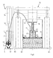
- the pump 35 comprises a double acting pneumatic cylinder 60 and presents one or, in other examples, two intake or delivery chambers 61 (one in the present example) which cooperate with an ink collection disc 63 to constantly feed the chamber 61, and with a pressing plate 64 which maintains the ink compacted by the action of one or two pneumatic cylinders 65 (two in the present example) which support the entire pump 35, making it translate relative to a base 66.
- the double acting pneumatic cylinder 60 is controlled by a system which alternately feeds compressed air into one and the other of its internal compartments, to provide continuous reciprocating movement.
- the chamber 61 performs both the intake function and the function of delivering ink to the device 30.
- the chamber 61 is cylindrical and presents an end part 68 of increased diameter, so that between the lower end of its wall and the collection disc 63 rigid with a rod 70 of the pneumatic cylinder 60, an annular channel is defined for entry of the ink into this chamber.
- the collection disc 63 adheres to the wall of the chamber 61 and compresses the ink present therein, to cause it to emerge through an upper aperture 71 to which the conduit 57 is connected, this latter being connected to the filling head 33 of the device 30; this conduit is preferably flexible.
- a first lower chamber (shaped as that previously described for the single chamber pump) performs the ink intake function, while a second upper chamber performs the delivery function.
- the intake chamber is connected to the delivery chamber via a non-return valve which enables the ink to pass from the intake chamber to the delivery chamber but not vice versa.
- the rod of the pneumatic cylinder (which passes through both the chambers, which are superposed) presents portions of different cross-section.
- the collection disc compresses the ink present in the intake chamber, making it flow through the non-return valve and into the delivery chamber, where it saturates its capacity.
- the central region of the delivery chamber firstly occupied by a portion of the pneumatic cylinder rod having a given cross-section, is occupied by a portion of the rod having a greater cross-section, such as to compress the ink present in the delivery chamber and cause it to emerge through a lateral aperture to which the flexible tube connecting to the device 30 is connected.
- a pneumatic-hydraulic pressure multiplier is formed in which the ratio of the double acting pneumatic cylinder cross-section to the cross-section of the hydraulic element formed by the intake and/or delivery chambers represents the pressure ratio RP; this means that by feeding the pneumatic cylinder with air at a pressure P1, the pump generates a pressure P2 corresponding to the product P1 x RP.
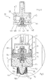
- the piston of the invention can have the non-return valve 7 opening in correspondence with a lateral wall thereof (as shown in Figure 7).
- the piston 5 presents a thick part 80 in the interior of which the non-return valve 7 is inserted along an axis 81 substantial perpendicular to the cartridge axis 82.
- the non-return valve 7 again presents the holes 11 disposed at 90 degrees apart to distribute the ink uniformly within the cartridge and also presents a further hole 83 which discharges the ink along the cartridge axis 82.
- the thick part 80 presents a seat 86 to receive a portion of a non-return valve 38 positioned at the end of the tube 57 from the pump 35.
- a spacer 87 provided with apertures 88 and 89 to allow ink passage is advantageously inserted into the cartridge 1.
- This embodiment of the device is particularly useful if large quantities of ink have to be fed without removing the cartridge 1 from the ink duct.
- the piston 5 with the non-return valve disposed along the axis 82 is removed from the previously described cartridge and the spacer is inserted; the cartridge is then closed by the piston 5 provided with the non-return valve disposed along the axis 81 perpendicular to the axis 82 and a hole 90 is made in correspondence with the seat 86.
- the actuator cylinder which during the operation of the previously described cartridge enables the ink to be discharged from the cartridge (not shown), is moved against the piston as indicated by the arrow F4, so that the piston remains locked (and at rest) between the said actuator cylinder and the spacer 87.
- the ink which arrives under pressure through the tube 57 passes through the valve 38 and the valve 7, enters the cartridge 1 through the holes 11, 83 and leaves the cartridge through the holes 51 to feed the ink duct with ink; during this process the piston 5 remains at rest.
- ink can be fed directly by the pump to the cartridge and from there to the ink duct.
Landscapes
- Inking, Control Or Cleaning Of Printing Machines (AREA)
- Ink Jet (AREA)
Applications Claiming Priority (2)
| Application Number | Priority Date | Filing Date | Title |
|---|---|---|---|
| ITMI20040883 | 2004-05-03 | ||
| IT000883A ITMI20040883A1 (it) | 2004-05-03 | 2004-05-03 | Cartuccia di alimentazione di inchiostro ad un calamaio di una macchina da stampa e dispositivo di riempimento di detta cartuccia |
Publications (2)
| Publication Number | Publication Date |
|---|---|
| EP1593507A1 true EP1593507A1 (de) | 2005-11-09 |
| EP1593507B1 EP1593507B1 (de) | 2009-12-23 |
Family
ID=34935804
Family Applications (1)
| Application Number | Title | Priority Date | Filing Date |
|---|---|---|---|
| EP05009195A Expired - Lifetime EP1593507B1 (de) | 2004-05-03 | 2005-04-27 | Kartusche zum Zuführen von Farbe in den Farbkasten einer Druckmaschine und Vorrichtung zum Füllen von der Kartusche |
Country Status (6)
| Country | Link |
|---|---|
| US (1) | US7614728B2 (de) |
| EP (1) | EP1593507B1 (de) |
| AT (1) | ATE452759T1 (de) |
| DE (1) | DE602005018412D1 (de) |
| ES (1) | ES2338569T3 (de) |
| IT (1) | ITMI20040883A1 (de) |
Cited By (1)
| Publication number | Priority date | Publication date | Assignee | Title |
|---|---|---|---|---|
| CN103802461A (zh) * | 2012-11-06 | 2014-05-21 | 海德堡印刷机械股份公司 | 用于可插入压出装置中的盒筒的前室 |
Families Citing this family (7)
| Publication number | Priority date | Publication date | Assignee | Title |
|---|---|---|---|---|
| KR20070078679A (ko) * | 2006-01-27 | 2007-08-01 | 삼성광주전자 주식회사 | 집진장치 |
| JP5747917B2 (ja) * | 2010-07-30 | 2015-07-15 | ブラザー工業株式会社 | 液体カートリッジ及び液体吐出装置 |
| US8430488B2 (en) * | 2010-12-27 | 2013-04-30 | Ciyuan Tan | Automatic vacuum ink container and its ink supply device and vacuum piston device |
| US8511805B2 (en) * | 2011-12-28 | 2013-08-20 | Hewlett-Packard Indigo B.V. | Extracting liquid from a cartridge |
| JP7673514B2 (ja) | 2021-06-18 | 2025-05-09 | ブラザー工業株式会社 | 液体供給装置及び液体供給システム |
| CN113664739B (zh) * | 2021-08-24 | 2022-11-18 | 浙江舒适体育用品有限公司 | 一种透出图案的砂纸及其制备装置和制备方法 |
| CN115257168B (zh) * | 2022-08-05 | 2023-12-12 | 温州铭大印业有限公司 | 一种用于纸箱生产的印刷装置及印刷方法 |
Citations (4)
| Publication number | Priority date | Publication date | Assignee | Title |
|---|---|---|---|---|
| EP0716923A1 (de) | 1994-12-16 | 1996-06-19 | BVS Beratung Verkauf Service Grafische Technik GmbH | Vorrichtung zur Versorgung eines Druckmaschinenfarbwerks mit Farbe |
| US5921181A (en) | 1996-08-14 | 1999-07-13 | Ritter; Ralf | Pneumatic cartridge expressing device |
| DE19953324A1 (de) | 1999-11-05 | 2001-05-23 | Technotrans Ag | Farbzufuhrsystem für Druckmaschinen |
| DE20317054U1 (de) | 2003-11-06 | 2004-02-19 | Lincoln Gmbh & Co. Kg | Farbzufuhradapter für Druckmaschinen |
Family Cites Families (7)
| Publication number | Priority date | Publication date | Assignee | Title |
|---|---|---|---|---|
| JPS5311886B1 (de) * | 1971-04-15 | 1978-04-25 | ||
| BE790094A (fr) | 1971-10-14 | 1973-02-01 | Colorflo Ltd | Perfectionnements aux appareils d'imprimerie |
| US5101219A (en) * | 1990-04-12 | 1992-03-31 | Gerber Garment Technology, Inc. | Long life pen and ink supply unit for x,y plotter and the like and related method of use |
| DE9406347U1 (de) * | 1994-04-15 | 1994-06-01 | Heidelberger Druckmaschinen Ag, 69115 Heidelberg | Vorrichtung zum Zuführen von Druckfarbe an Rotationsdruckmaschinen |
| GB2314592B (en) | 1996-06-27 | 2000-08-02 | Michael John Start | Dispensing system |
| JPH1120179A (ja) * | 1997-06-27 | 1999-01-26 | Tec Corp | インクジェットプリンタ |
| DE19757161A1 (de) * | 1997-12-20 | 1999-06-24 | Heidelberger Druckmasch Ag | Verfahren und Vorrichtung zum Zuführen von Druckfarbe im Farbwerk von Druckmaschinen |
-
2004
- 2004-05-03 IT IT000883A patent/ITMI20040883A1/it unknown
-
2005
- 2005-04-27 DE DE602005018412T patent/DE602005018412D1/de not_active Expired - Lifetime
- 2005-04-27 AT AT05009195T patent/ATE452759T1/de not_active IP Right Cessation
- 2005-04-27 EP EP05009195A patent/EP1593507B1/de not_active Expired - Lifetime
- 2005-04-27 ES ES05009195T patent/ES2338569T3/es not_active Expired - Lifetime
- 2005-05-03 US US11/119,753 patent/US7614728B2/en not_active Expired - Fee Related
Patent Citations (4)
| Publication number | Priority date | Publication date | Assignee | Title |
|---|---|---|---|---|
| EP0716923A1 (de) | 1994-12-16 | 1996-06-19 | BVS Beratung Verkauf Service Grafische Technik GmbH | Vorrichtung zur Versorgung eines Druckmaschinenfarbwerks mit Farbe |
| US5921181A (en) | 1996-08-14 | 1999-07-13 | Ritter; Ralf | Pneumatic cartridge expressing device |
| DE19953324A1 (de) | 1999-11-05 | 2001-05-23 | Technotrans Ag | Farbzufuhrsystem für Druckmaschinen |
| DE20317054U1 (de) | 2003-11-06 | 2004-02-19 | Lincoln Gmbh & Co. Kg | Farbzufuhradapter für Druckmaschinen |
Cited By (1)
| Publication number | Priority date | Publication date | Assignee | Title |
|---|---|---|---|---|
| CN103802461A (zh) * | 2012-11-06 | 2014-05-21 | 海德堡印刷机械股份公司 | 用于可插入压出装置中的盒筒的前室 |
Also Published As
| Publication number | Publication date |
|---|---|
| EP1593507B1 (de) | 2009-12-23 |
| US7614728B2 (en) | 2009-11-10 |
| US20050243150A1 (en) | 2005-11-03 |
| DE602005018412D1 (de) | 2010-02-04 |
| ATE452759T1 (de) | 2010-01-15 |
| ITMI20040883A1 (it) | 2004-08-03 |
| ES2338569T3 (es) | 2010-05-10 |
Similar Documents
| Publication | Publication Date | Title |
|---|---|---|
| US5479968A (en) | Ink filling apparatus and method for filling ink cartridges | |
| US7614728B2 (en) | Cartridge for feeding ink to an ink duct of a printing machine and device for filling said cartridge | |
| US7931461B2 (en) | Mould member for moulding three-dimensional products, system and methods of manufacturing a mould member | |
| CN101676111B (zh) | 液体供给装置、印刷装置及液体供给装置的控制方法 | |
| EP0857573A2 (de) | Verfahren zur Herstellung einer Tintenkassette zur Verwendung in einem Tintenstrahldrucker | |
| US20100200617A1 (en) | Cartridge piston with venting device | |
| US9360799B2 (en) | Toner filling apparatus | |
| DE19637879C2 (de) | Verfahren zum Nachfüllen eines Tintenvorrats für einen Tintenstrahldrucker, nachfüllbarer Tintenvorrat und Nachfüllvorrichtung | |
| JP5413229B2 (ja) | 液体噴射装置 | |
| CN100384701C (zh) | 用于分发单个药片的分发器 | |
| JP5227708B2 (ja) | 粉粒体の分配装置および分配方法 | |
| EP3439517B1 (de) | Brüheinheit, maschine und system zur herstellung eines getränks unter verwendung von vorverpackten kapseln | |
| US20230294906A1 (en) | Method For Emptying Viscous Material Out Of A Cartridge That Is Open At Both Ends | |
| KR100576192B1 (ko) | 스텐실 인쇄 잉크 용기, 스텐실 인쇄 잉크 카트리지, 잉크카트리지 제조 방법 및 잉크 용기용 내부 플러그 | |
| JP2014024347A (ja) | 液体噴射装置 | |
| US20020186286A1 (en) | Ink cartridge providing improved ink supply | |
| JP4947591B2 (ja) | トリガー式液体噴出器 | |
| US1947535A (en) | Dripless nozzle for filling machines | |
| US6502932B1 (en) | Print head device and ink jet printer including the print head device | |
| CN108215512A (zh) | 一种打印机墨盒的加墨方法 | |
| KR20220125487A (ko) | 잉크 카트리지용 잉크 공급장치 | |
| CN218171783U (zh) | 一种印刷机用供墨组件 | |
| RU2836772C1 (ru) | Способ перезаправки контейнера с дозирующим насосом, а также соответствующие картридж для перезаправки и аппарат | |
| CN106827820B (zh) | 打印机墨盒 | |
| KR200203789Y1 (ko) | 압축공기용 자동식 구리스기의 교체용 용기 |
Legal Events
| Date | Code | Title | Description |
|---|---|---|---|
| PUAI | Public reference made under article 153(3) epc to a published international application that has entered the european phase |
Free format text: ORIGINAL CODE: 0009012 |
|
| AK | Designated contracting states |
Kind code of ref document: A1 Designated state(s): AT BE BG CH CY CZ DE DK EE ES FI FR GB GR HU IE IS IT LI LT LU MC NL PL PT RO SE SI SK TR |
|
| AX | Request for extension of the european patent |
Extension state: AL BA HR LV MK YU |
|
| 17P | Request for examination filed |
Effective date: 20060118 |
|
| AKX | Designation fees paid |
Designated state(s): AT BE BG CH CY CZ DE DK EE ES FI FR GB GR HU IE IS IT LI LT LU MC NL PL PT RO SE SI SK TR |
|
| AXX | Extension fees paid |
Extension state: AL Payment date: 20060118 Extension state: BA Payment date: 20060118 Extension state: HR Payment date: 20060118 Extension state: MK Payment date: 20060118 Extension state: YU Payment date: 20060118 |
|
| 17Q | First examination report despatched |
Effective date: 20090409 |
|
| GRAP | Despatch of communication of intention to grant a patent |
Free format text: ORIGINAL CODE: EPIDOSNIGR1 |
|
| GRAS | Grant fee paid |
Free format text: ORIGINAL CODE: EPIDOSNIGR3 |
|
| GRAA | (expected) grant |
Free format text: ORIGINAL CODE: 0009210 |
|
| AK | Designated contracting states |
Kind code of ref document: B1 Designated state(s): AT BE BG CH CY CZ DE DK EE ES FI FR GB GR HU IE IS IT LI LT LU MC NL PL PT RO SE SI SK TR |
|
| AX | Request for extension of the european patent |
Extension state: AL BA HR MK YU |
|
| REG | Reference to a national code |
Ref country code: GB Ref legal event code: FG4D |
|
| REG | Reference to a national code |
Ref country code: CH Ref legal event code: EP |
|
| REG | Reference to a national code |
Ref country code: IE Ref legal event code: FG4D |
|
| REF | Corresponds to: |
Ref document number: 602005018412 Country of ref document: DE Date of ref document: 20100204 Kind code of ref document: P |
|
| REG | Reference to a national code |
Ref country code: NL Ref legal event code: VDEP Effective date: 20091223 |
|
| PG25 | Lapsed in a contracting state [announced via postgrant information from national office to epo] |
Ref country code: FI Free format text: LAPSE BECAUSE OF FAILURE TO SUBMIT A TRANSLATION OF THE DESCRIPTION OR TO PAY THE FEE WITHIN THE PRESCRIBED TIME-LIMIT Effective date: 20091223 Ref country code: SE Free format text: LAPSE BECAUSE OF FAILURE TO SUBMIT A TRANSLATION OF THE DESCRIPTION OR TO PAY THE FEE WITHIN THE PRESCRIBED TIME-LIMIT Effective date: 20091223 Ref country code: LT Free format text: LAPSE BECAUSE OF FAILURE TO SUBMIT A TRANSLATION OF THE DESCRIPTION OR TO PAY THE FEE WITHIN THE PRESCRIBED TIME-LIMIT Effective date: 20091223 |
|
| REG | Reference to a national code |
Ref country code: ES Ref legal event code: FG2A Ref document number: 2338569 Country of ref document: ES Kind code of ref document: T3 |
|
| LTIE | Lt: invalidation of european patent or patent extension |
Effective date: 20091223 |
|
| PG25 | Lapsed in a contracting state [announced via postgrant information from national office to epo] |
Ref country code: PL Free format text: LAPSE BECAUSE OF FAILURE TO SUBMIT A TRANSLATION OF THE DESCRIPTION OR TO PAY THE FEE WITHIN THE PRESCRIBED TIME-LIMIT Effective date: 20091223 Ref country code: SI Free format text: LAPSE BECAUSE OF FAILURE TO SUBMIT A TRANSLATION OF THE DESCRIPTION OR TO PAY THE FEE WITHIN THE PRESCRIBED TIME-LIMIT Effective date: 20091223 |
|
| PG25 | Lapsed in a contracting state [announced via postgrant information from national office to epo] |
Ref country code: AT Free format text: LAPSE BECAUSE OF FAILURE TO SUBMIT A TRANSLATION OF THE DESCRIPTION OR TO PAY THE FEE WITHIN THE PRESCRIBED TIME-LIMIT Effective date: 20091223 |
|
| PG25 | Lapsed in a contracting state [announced via postgrant information from national office to epo] |
Ref country code: NL Free format text: LAPSE BECAUSE OF FAILURE TO SUBMIT A TRANSLATION OF THE DESCRIPTION OR TO PAY THE FEE WITHIN THE PRESCRIBED TIME-LIMIT Effective date: 20091223 Ref country code: IS Free format text: LAPSE BECAUSE OF FAILURE TO SUBMIT A TRANSLATION OF THE DESCRIPTION OR TO PAY THE FEE WITHIN THE PRESCRIBED TIME-LIMIT Effective date: 20100423 Ref country code: BG Free format text: LAPSE BECAUSE OF FAILURE TO SUBMIT A TRANSLATION OF THE DESCRIPTION OR TO PAY THE FEE WITHIN THE PRESCRIBED TIME-LIMIT Effective date: 20100323 Ref country code: EE Free format text: LAPSE BECAUSE OF FAILURE TO SUBMIT A TRANSLATION OF THE DESCRIPTION OR TO PAY THE FEE WITHIN THE PRESCRIBED TIME-LIMIT Effective date: 20091223 Ref country code: RO Free format text: LAPSE BECAUSE OF FAILURE TO SUBMIT A TRANSLATION OF THE DESCRIPTION OR TO PAY THE FEE WITHIN THE PRESCRIBED TIME-LIMIT Effective date: 20091223 Ref country code: PT Free format text: LAPSE BECAUSE OF FAILURE TO SUBMIT A TRANSLATION OF THE DESCRIPTION OR TO PAY THE FEE WITHIN THE PRESCRIBED TIME-LIMIT Effective date: 20100423 |
|
| PG25 | Lapsed in a contracting state [announced via postgrant information from national office to epo] |
Ref country code: SK Free format text: LAPSE BECAUSE OF FAILURE TO SUBMIT A TRANSLATION OF THE DESCRIPTION OR TO PAY THE FEE WITHIN THE PRESCRIBED TIME-LIMIT Effective date: 20091223 Ref country code: CZ Free format text: LAPSE BECAUSE OF FAILURE TO SUBMIT A TRANSLATION OF THE DESCRIPTION OR TO PAY THE FEE WITHIN THE PRESCRIBED TIME-LIMIT Effective date: 20091223 Ref country code: BE Free format text: LAPSE BECAUSE OF FAILURE TO SUBMIT A TRANSLATION OF THE DESCRIPTION OR TO PAY THE FEE WITHIN THE PRESCRIBED TIME-LIMIT Effective date: 20091223 |
|
| PG25 | Lapsed in a contracting state [announced via postgrant information from national office to epo] |
Ref country code: CY Free format text: LAPSE BECAUSE OF FAILURE TO SUBMIT A TRANSLATION OF THE DESCRIPTION OR TO PAY THE FEE WITHIN THE PRESCRIBED TIME-LIMIT Effective date: 20091223 Ref country code: GR Free format text: LAPSE BECAUSE OF FAILURE TO SUBMIT A TRANSLATION OF THE DESCRIPTION OR TO PAY THE FEE WITHIN THE PRESCRIBED TIME-LIMIT Effective date: 20100324 |
|
| PLBE | No opposition filed within time limit |
Free format text: ORIGINAL CODE: 0009261 |
|
| STAA | Information on the status of an ep patent application or granted ep patent |
Free format text: STATUS: NO OPPOSITION FILED WITHIN TIME LIMIT |
|
| PG25 | Lapsed in a contracting state [announced via postgrant information from national office to epo] |
Ref country code: MC Free format text: LAPSE BECAUSE OF NON-PAYMENT OF DUE FEES Effective date: 20100430 |
|
| REG | Reference to a national code |
Ref country code: CH Ref legal event code: PL |
|
| 26N | No opposition filed |
Effective date: 20100924 |
|
| PG25 | Lapsed in a contracting state [announced via postgrant information from national office to epo] |
Ref country code: IE Free format text: LAPSE BECAUSE OF NON-PAYMENT OF DUE FEES Effective date: 20100427 Ref country code: DK Free format text: LAPSE BECAUSE OF FAILURE TO SUBMIT A TRANSLATION OF THE DESCRIPTION OR TO PAY THE FEE WITHIN THE PRESCRIBED TIME-LIMIT Effective date: 20091223 |
|
| PG25 | Lapsed in a contracting state [announced via postgrant information from national office to epo] |
Ref country code: CH Free format text: LAPSE BECAUSE OF NON-PAYMENT OF DUE FEES Effective date: 20100430 Ref country code: LI Free format text: LAPSE BECAUSE OF NON-PAYMENT OF DUE FEES Effective date: 20100430 |
|
| PG25 | Lapsed in a contracting state [announced via postgrant information from national office to epo] |
Ref country code: HU Free format text: LAPSE BECAUSE OF FAILURE TO SUBMIT A TRANSLATION OF THE DESCRIPTION OR TO PAY THE FEE WITHIN THE PRESCRIBED TIME-LIMIT Effective date: 20100624 Ref country code: LU Free format text: LAPSE BECAUSE OF NON-PAYMENT OF DUE FEES Effective date: 20100427 |
|
| PG25 | Lapsed in a contracting state [announced via postgrant information from national office to epo] |
Ref country code: TR Free format text: LAPSE BECAUSE OF FAILURE TO SUBMIT A TRANSLATION OF THE DESCRIPTION OR TO PAY THE FEE WITHIN THE PRESCRIBED TIME-LIMIT Effective date: 20091223 |
|
| REG | Reference to a national code |
Ref country code: FR Ref legal event code: PLFP Year of fee payment: 11 |
|
| PGFP | Annual fee paid to national office [announced via postgrant information from national office to epo] |
Ref country code: GB Payment date: 20150331 Year of fee payment: 11 |
|
| PGFP | Annual fee paid to national office [announced via postgrant information from national office to epo] |
Ref country code: ES Payment date: 20150427 Year of fee payment: 11 Ref country code: DE Payment date: 20150422 Year of fee payment: 11 |
|
| PGFP | Annual fee paid to national office [announced via postgrant information from national office to epo] |
Ref country code: FR Payment date: 20150417 Year of fee payment: 11 |
|
| PGFP | Annual fee paid to national office [announced via postgrant information from national office to epo] |
Ref country code: IT Payment date: 20160323 Year of fee payment: 12 |
|
| REG | Reference to a national code |
Ref country code: DE Ref legal event code: R119 Ref document number: 602005018412 Country of ref document: DE |
|
| GBPC | Gb: european patent ceased through non-payment of renewal fee |
Effective date: 20160427 |
|
| REG | Reference to a national code |
Ref country code: FR Ref legal event code: ST Effective date: 20161230 |
|
| PG25 | Lapsed in a contracting state [announced via postgrant information from national office to epo] |
Ref country code: GB Free format text: LAPSE BECAUSE OF NON-PAYMENT OF DUE FEES Effective date: 20160427 Ref country code: DE Free format text: LAPSE BECAUSE OF NON-PAYMENT OF DUE FEES Effective date: 20161101 Ref country code: FR Free format text: LAPSE BECAUSE OF NON-PAYMENT OF DUE FEES Effective date: 20160502 |
|
| PG25 | Lapsed in a contracting state [announced via postgrant information from national office to epo] |
Ref country code: IT Free format text: LAPSE BECAUSE OF NON-PAYMENT OF DUE FEES Effective date: 20170427 Ref country code: ES Free format text: LAPSE BECAUSE OF NON-PAYMENT OF DUE FEES Effective date: 20160428 |
|
| REG | Reference to a national code |
Ref country code: ES Ref legal event code: FD2A Effective date: 20181205 |