EP1593595A2 - Système électrothermique de protection contre le givre, pulsé et à consommation faible - Google Patents
Système électrothermique de protection contre le givre, pulsé et à consommation faible Download PDFInfo
- Publication number
- EP1593595A2 EP1593595A2 EP05009371A EP05009371A EP1593595A2 EP 1593595 A2 EP1593595 A2 EP 1593595A2 EP 05009371 A EP05009371 A EP 05009371A EP 05009371 A EP05009371 A EP 05009371A EP 1593595 A2 EP1593595 A2 EP 1593595A2
- Authority
- EP
- European Patent Office
- Prior art keywords
- metal foil
- heater
- parting strip
- airfoil
- ice
- Prior art date
- Legal status (The legal status is an assumption and is not a legal conclusion. Google has not performed a legal analysis and makes no representation as to the accuracy of the status listed.)
- Granted
Links
- 239000011888 foil Substances 0.000 claims abstract description 157
- 229910052751 metal Inorganic materials 0.000 claims abstract description 154
- 239000002184 metal Substances 0.000 claims abstract description 154
- PXHVJJICTQNCMI-UHFFFAOYSA-N Nickel Chemical compound [Ni] PXHVJJICTQNCMI-UHFFFAOYSA-N 0.000 claims abstract description 60
- RTAQQCXQSZGOHL-UHFFFAOYSA-N Titanium Chemical compound [Ti] RTAQQCXQSZGOHL-UHFFFAOYSA-N 0.000 claims abstract description 48
- 229910052759 nickel Inorganic materials 0.000 claims abstract description 30
- 230000015572 biosynthetic process Effects 0.000 claims abstract description 27
- 239000004020 conductor Substances 0.000 claims abstract description 24
- 239000000463 material Substances 0.000 claims abstract description 22
- RYGMFSIKBFXOCR-UHFFFAOYSA-N Copper Chemical compound [Cu] RYGMFSIKBFXOCR-UHFFFAOYSA-N 0.000 claims abstract description 13
- 229910052802 copper Inorganic materials 0.000 claims abstract description 12
- 239000010949 copper Substances 0.000 claims abstract description 12
- 238000004519 manufacturing process Methods 0.000 claims abstract description 3
- 238000010438 heat treatment Methods 0.000 claims description 80
- 238000004146 energy storage Methods 0.000 claims description 39
- 238000005755 formation reaction Methods 0.000 claims description 26
- 238000000034 method Methods 0.000 claims description 21
- 239000010936 titanium Substances 0.000 claims description 15
- 229910052719 titanium Inorganic materials 0.000 claims description 15
- 238000002955 isolation Methods 0.000 claims description 6
- 238000009413 insulation Methods 0.000 claims description 5
- 238000007747 plating Methods 0.000 claims description 5
- 239000000853 adhesive Substances 0.000 claims description 4
- 230000001070 adhesive effect Effects 0.000 claims description 4
- 230000004888 barrier function Effects 0.000 claims description 3
- 239000002131 composite material Substances 0.000 claims description 3
- 238000007599 discharging Methods 0.000 claims description 3
- 230000008878 coupling Effects 0.000 claims description 2
- 238000010168 coupling process Methods 0.000 claims description 2
- 238000005859 coupling reaction Methods 0.000 claims description 2
- 238000002844 melting Methods 0.000 claims description 2
- 230000008018 melting Effects 0.000 claims description 2
- 238000009877 rendering Methods 0.000 claims description 2
- 238000005476 soldering Methods 0.000 claims 2
- 238000007772 electroless plating Methods 0.000 claims 1
- 238000009713 electroplating Methods 0.000 claims 1
- 238000007493 shaping process Methods 0.000 claims 1
- 239000010410 layer Substances 0.000 description 34
- 238000010586 diagram Methods 0.000 description 6
- 238000013461 design Methods 0.000 description 5
- 238000000707 layer-by-layer assembly Methods 0.000 description 4
- 230000033001 locomotion Effects 0.000 description 4
- 239000000126 substance Substances 0.000 description 4
- 238000005299 abrasion Methods 0.000 description 3
- 230000000694 effects Effects 0.000 description 3
- 230000003628 erosive effect Effects 0.000 description 3
- 230000009467 reduction Effects 0.000 description 3
- 230000002829 reductive effect Effects 0.000 description 3
- 101100163833 Arabidopsis thaliana ARP6 gene Proteins 0.000 description 2
- WYTGDNHDOZPMIW-RCBQFDQVSA-N alstonine Natural products C1=CC2=C3C=CC=CC3=NC2=C2N1C[C@H]1[C@H](C)OC=C(C(=O)OC)[C@H]1C2 WYTGDNHDOZPMIW-RCBQFDQVSA-N 0.000 description 2
- 238000005868 electrolysis reaction Methods 0.000 description 2
- 239000007788 liquid Substances 0.000 description 2
- 229910044991 metal oxide Inorganic materials 0.000 description 2
- 150000004706 metal oxides Chemical class 0.000 description 2
- 230000008569 process Effects 0.000 description 2
- 239000004065 semiconductor Substances 0.000 description 2
- 239000004952 Polyamide Substances 0.000 description 1
- 239000012790 adhesive layer Substances 0.000 description 1
- 230000008901 benefit Effects 0.000 description 1
- 230000033228 biological regulation Effects 0.000 description 1
- 239000012141 concentrate Substances 0.000 description 1
- 238000007796 conventional method Methods 0.000 description 1
- 230000003247 decreasing effect Effects 0.000 description 1
- 230000001419 dependent effect Effects 0.000 description 1
- 230000003292 diminished effect Effects 0.000 description 1
- 238000009429 electrical wiring Methods 0.000 description 1
- 238000003487 electrochemical reaction Methods 0.000 description 1
- 230000007613 environmental effect Effects 0.000 description 1
- 239000011152 fibreglass Substances 0.000 description 1
- 230000005669 field effect Effects 0.000 description 1
- 239000007789 gas Substances 0.000 description 1
- 230000000670 limiting effect Effects 0.000 description 1
- 239000007769 metal material Substances 0.000 description 1
- 230000005012 migration Effects 0.000 description 1
- 238000013508 migration Methods 0.000 description 1
- 229920002647 polyamide Polymers 0.000 description 1
- 238000010248 power generation Methods 0.000 description 1
- 239000011241 protective layer Substances 0.000 description 1
- 238000000926 separation method Methods 0.000 description 1
- 238000012163 sequencing technique Methods 0.000 description 1
- 238000012360 testing method Methods 0.000 description 1
- 238000012546 transfer Methods 0.000 description 1
- XLYOFNOQVPJJNP-UHFFFAOYSA-N water Substances O XLYOFNOQVPJJNP-UHFFFAOYSA-N 0.000 description 1
- 238000009736 wetting Methods 0.000 description 1
Images


Classifications
-
- F—MECHANICAL ENGINEERING; LIGHTING; HEATING; WEAPONS; BLASTING
- F01—MACHINES OR ENGINES IN GENERAL; ENGINE PLANTS IN GENERAL; STEAM ENGINES
- F01D—NON-POSITIVE DISPLACEMENT MACHINES OR ENGINES, e.g. STEAM TURBINES
- F01D25/00—Component parts, details, or accessories, not provided for in, or of interest apart from, other groups
- F01D25/02—De-icing means for engines having icing phenomena
-
- B—PERFORMING OPERATIONS; TRANSPORTING
- B64—AIRCRAFT; AVIATION; COSMONAUTICS
- B64D—EQUIPMENT FOR FITTING IN OR TO AIRCRAFT; FLIGHT SUITS; PARACHUTES; ARRANGEMENT OR MOUNTING OF POWER PLANTS OR PROPULSION TRANSMISSIONS IN AIRCRAFT
- B64D15/00—De-icing or preventing icing on exterior surfaces of aircraft
- B64D15/12—De-icing or preventing icing on exterior surfaces of aircraft by electric heating
- B64D15/14—De-icing or preventing icing on exterior surfaces of aircraft by electric heating controlled cyclically along length of surface
-
- Y—GENERAL TAGGING OF NEW TECHNOLOGICAL DEVELOPMENTS; GENERAL TAGGING OF CROSS-SECTIONAL TECHNOLOGIES SPANNING OVER SEVERAL SECTIONS OF THE IPC; TECHNICAL SUBJECTS COVERED BY FORMER USPC CROSS-REFERENCE ART COLLECTIONS [XRACs] AND DIGESTS
- Y02—TECHNOLOGIES OR APPLICATIONS FOR MITIGATION OR ADAPTATION AGAINST CLIMATE CHANGE
- Y02T—CLIMATE CHANGE MITIGATION TECHNOLOGIES RELATED TO TRANSPORTATION
- Y02T50/00—Aeronautics or air transport
- Y02T50/60—Efficient propulsion technologies, e.g. for aircraft
Definitions
- the present invention is related to electro-thermal ice protection systems for aero structures, in general:
- a metal foil heater including an integral parting strip, configurable to cover at least a portion of a leading edge of an airfoil; and a controller for controlling heating energy to the metal foil of the heater in accordance with a pulse duty-cycle and for controlling heating energy to the parting strip to maintain an air-stagnation zone of the leading edge virtually free of ice formation.
- Electro-thermal de-icing or anti-icing products for leading edge ice protection of aero surfaces generally utilize heating elements or electrodes disposed at a leading edge surface of the aero structure in the form of a serpentine or interdigitated finger area grid to deliver heating power to ice which may be formed thereon.
- One such proposed electro-thermal ice protection product operates in an electro-chemical mode in which energy is delivered through capacitive coupling to the accreted ice by high frequency (HF) audio electro-chemical heating. Through an electrolysis reaction, gases are generated at the ice-surface interface which tend to affect the ice adhesive bond and separate the ice from the surface.
- HF high frequency
- the electro-chemical heating method fails to perform at low temperatures, like below -20° C, for example, because the ice which is a protonic semiconductor is not conductive enough at these temperatures to allow significant power to be imparted at voltage levels that are consistent with safe aero design practice as dictated by the U.S. FAA regulations and FAA advisory circular bulletins such as AC 25.981, for example.
- conductive heater electrodes have been proposed to be disposed on, but insulated from, the aero surfaces to be protected from ice in parallel finger patterns which ran the length of the heater.
- each finger had a width dimension of 0.020 inches or 20 mils with a separation distance from adjacent fingers of 20 mils, and a thickness dimension of 0.004 inches or 4 mils.
- this bare metal surface heater arrangement was found not to be structurally sound when tested under airfoil flight conditions, especially under rain erosion and particulate abrasion conditions. Any layer of material disposed over the heater grid for protection against rain erosion and particulate abrasion conditions will cause heat losses which will impose additional heating power requirements for ice protection.
- power supply systems on-board the aero structure can not afford to provide such ice protection power without affecting the power requirements to other systems.
- Petrenko recognized that there is a liquid like layer (LLL) at the ice interface between the ice layer and aero structure which is a major factor in the ice adhesion strength. Petrenko realized that the LLL functions as a wetting surface which substantially increases the effective contact area between surfaces.
- the Petrenko system comprises a first electrode connected to the aero surface, preferably in the form of a grid, an electrically insulating layer disposed over the first electrode, and a second electrode formed over the first electrode in a similar grid as the first electrode. In operation, when ice is detected on the surface, a DC voltage is applied across the first and second electrode grids of sufficient magnitude to decrease the ice adhesion strength of the LLL and facilitate ice removal by the wind slipstream across the aero surface.
- Petrenko system proposes a similar grid of electrodes either in a serpentine or interdigitated design which couple energy into the ice layer accreted on an aero structure to loosen the bond between the ice and aero surface, it will suffer similar structural and power requirement drawbacks in an aero structure flight environment as described for the AC electro-chemical heating system above.
- the present invention overcomes the aforementioned drawbacks of the present electro-thermal ice protection systems and offers an electro-thermal ice protection system rugged enough to withstand exposure to an aero structure operational environment, and capable of shedding ice from an aero surface at safe voltages and substantially reduced power levels, and before the ice accretes to a dangerous thickness level.
- an electro-thermal ice protection system for an airfoil comprises: a metal foil heater including an integral parting strip, the metal foil heater configurable to cover at least a portion of a leading edge of the airfoil with the integral parting strip disposed along an air-stagnation zone of the leading edge; and a controller coupled electrically to the metal foil heater for controlling electrical energy from a power source to the metal foil of the heater in accordance with a pulse duty-cycle and for controlling power to the parting strip of the heater to maintain the air-stagnation zone virtually free of ice formation.
- a method of making a metal foil heater for use in ice protection of an airfoil comprises the steps of: preparing a sheet of Titanium foil in a rectangular shape having a length substantially greater than a width thereof for covering at least a portion of a leading edge of the airfoil; applying a layer of Nickel material over an area along each width edge of the Titanium foil; applying a layer of Copper material over the Nickel layer along each width edge of the Titanium foil; and attaching conductor wires to the Copper layers at each width edge.
- an ice protection system for an airfoil comprises: at least one metal foil heater covering at least a portion of a leading edge of the airfoil, the at least one metal foil heater coupled at a region through a conductor to a conductive structure of the airfoil for distributing electrical energy of a lightning strike from the region through the conductor to the conductive structure; and a converter powered by a power source for supplying electrical heating energy to the at least one metal foil heater over source and return lines which are electrically isolated from the power source, the converter for preventing the electrical heating energy from being conducted through the conductive structure of the airfoil.
- an electro-thermal ice protection system for an airfoil comprises: a plurality of metal foil heaters, each heater of the plurality for covering a segment of a leading edge of the airfoil; and a controller coupled electrically to the plurality of metal foil heaters for multiplexing electrical energy from a power source among the plurality of heaters in accordance with a pulse duty-cycle.
- an electro-thermal ice protection system for an airfoil comprises: a metal foil heater including a plurality of integral parting strip segments, the metal foil heater configurable to cover at least a portion of a leading edge of the airfoil with each integral parting strip segment of the plurality disposed along a corresponding segment of an air-stagnation zone of the leading edge; and a controller coupled electrically to the metal foil heater for controlling electrical energy from a power source to the metal foil of the heater and for controlling power to the plurality of parting strip segments of the heater to maintain at least a segment of the air-stagnation zone virtually free of ice formation.
- an electro-thermal ice protection apparatus for an airfoil comprises: a metal foil heater configurable to cover at least a portion of a leading edge of the airfoil, a metal foil surface of the heater including a parting strip area disposed along an air stagnation zone of the leading edge, and top and bottom shed areas on either side thereof; and a parting strip comprising a multiplicity of differently shaped island areas disposed on the metal foil surface within the parting strip area, each island area being separated from the other island areas by the metal foil surface.
- an electro-thermal ice protection system for an airfoil comprises: a metal foil heater configurable to cover at least a portion of a leading edge of the airfoil, a metal foil surface of the heater including a parting strip area disposed along an air stagnation zone of the leading edge, and top and bottom shed areas on either side thereof a parting strip comprising a multiplicity of differently shaped island areas disposed on the metal foil surface within the parting strip area, each island area being separated from the other island areas by the metal foil surface; first and second conductors connected to the top shed area of the metal foil; third and fourth conductors connected to the bottom shed area of the metal foil; and a controller for controlling heating energy from a power source to the metal foil heater through the first, second, third and fourth conductors.
- a method of protecting an airfoil against undesired ice formation comprises the steps of: configuring a metal foil heater to cover at least a portion of a leading edge of the airfoil; defining a parting strip area on a metal foil surface of the heater along an air stagnation zone of the leading edge; defining top and bottom shed areas on the metal foil surface on either side of the parting strip area; disposing a multiplicity of differently shaped island areas on the metal foil surface within the parting strip area, and separating each island area from the other island areas by the metal foil surface; and controlling heating energy through the parting strip area, the top shed area and the bottom shed area of the metal foil heater in a controlled sequence at different energy levels.
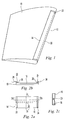
- Figure 1 is an isometric illustration of an airfoil section of an aero structure suitable for embodying one aspect of the present invention.
- Figures 2A, 2B and 2C are plan, side and profile views of an exemplary metal foil heater suitable for use in the embodiment of Figure 1.
- Figure 3 is a cross-sectional view of the metal foil heater disposed over a leading edge of the airfoil in accordance with one embodiment of the present invention.
- Figure 4 is a cross-sectional view of the metal foil heater disposed over a leading edge of the airfoil in accordance with another embodiment of the present invention.
- Figure 5 is a block diagram schematic of an exemplary controller for the metal foil heater suitable for embodying another aspect of the present invention.
- Figure 6 is an illustration of an alternate embodiment of the present invention including a plurality of heating elements disposed along the span of the leading edge of the airfoil.
- Figure 7 is a sketch of exemplary control circuitry suitable for use in controlling the heating of the plurality of heating elements disposed on the airfoil as depicted in Figure 6.
- Figure 8 is a sketch of an alternate embodiment of control circuitry suitable for use in controlling the heating of the plurality of heating elements disposed on the airfoil as depicted in Figure 6.
- Figure 9 is a sketch of another alternate embodiment of control circuitry suitable for use in controlling the heating of the plurality of heating elements utilizing a corresponding plurality of energy storage units.
- Figure 10 is an embodiment of another aspect of the present invention utilizing a plurality of narrow parting strips integral to the metal foil heater for maintaining the air-stagnation zone of the airfoil virtually free of ice.
- Figure 11 is a block diagram schematic of an exemplary controller suitable for use in the embodiment of Figure 10.
- Figure 12 is an embodiment of yet another aspect of the present invention utilizing an integral parting strip comprising a multiplicity of island areas in a parting strip area of a metal foil heater.
- Figure 13 is a block diagram schematic of an exemplary controller suitable for use in the embodiment of Figure 12.
- Figure 1 is an isometric illustration of an airfoil section 10 of an aero structure suitable for embodying one aspect of the present invention.
- a metal foil heater 14 wrapped around a leading edge 12 of the airfoil 10 in a C-shaped configuration is a metal foil heater 14.
- the metal material of foil heater 14 should be durable under and resistant to flight conditions of the airfoil 10, such as raindrop erosion and particulate abrasion, for example.
- the foil heater 14 comprises a rectangular sheet of Titanium having a thickness of approximately 0.004 inches or 4 mils with dimensions of approximately 66 inches in length and approximately 11 to 13 inches in width, for example.
- Titanium foil heater 14 suitable for embodying the principles of the present invention is shown in plan, side and profile views in Figures 2A, 2B and 2C, respectively.
- a Titanium metal sheet or layer 16 is disposed over an insulating layer 18 which may have a thickness of approximately 0.0005 to 0.050 inches, for example.
- the Titanium foil sheet 16 is attached to the insulating layer 18 using aircraft-approved adhesives.
- the side of the Titanium layer 16 in juxtaposition with the insulating layer 18 may be chemically treated to improve surface adhesion therebetween.
- the insulating layer 18, which may be comprised ofKapton, Fiberglass, a polyamide material or the like, for example, provides both electrical and thermal isolation between the Titanium foil 16 and the airfoil 10.
- a parting strip 20 which maybe approximately 0.625 inches wide and 0.020 inches thick, for example, may be embedded within the insulation layer 20 down the length of the foil heater at approximately the center thereof.
- the parting strip 20 may be of the same material as the foil sheet 16 and electrically insulated therefrom.
- Copper bus bars 22 and 24 are disposed on the foil sheet 16 respectively across the widthwise edges thereof. Since Copper may not be conveniently soldered or brazed directly to the Titanium sheet, the Titanium foil 16 will need treatment in the edge areas where the bus bars 22 and 24 are to be attached.
- layers of Nickel 26 are plated to the Titanium foil 16 at the widthwise edge areas to a thickness of approximately 0.001 to 0.003 inches, for example. Then, the Titanium foil 16 is heat treated preferably at temperatures close to the melting point of the Nickel material for approximately one to four hours to form a better bond of Nickel to Titanium.
- a layer of Nickel may be electro less plated to the Titanium sheet 16 along the widthwise edge areas followed by a final or top layer of Nickel electro plated to the electro less plated Nickel layer to improve the adhesion of the nickel to the Titanium.
- the Copper bus bars 22 and 24 are soldered to the Nickel layers 26 at the widthwise edges of the Titanium foil 16,
- Conductor wires 28 and 30 are soldered to the bus bars 22 and 24, respectively, to conduct electrical energy from an electrical source to heat the Titanium foil 16 as will become more evident from the following description.
- the parting strip 20 also comprises Titanium in the present embodiment, electrical wiring connections may be made at the ends thereof in the same or similar manner as that just described for the metal foil 16, for example.
- FIG. 3 A cross-sectional depiction of the airfoil 10 and foil heater 14 is shown in Figure 3 to better illustrate the configuration of the present embodiment.
- the width of the foil heater 14 is wrapped chord wise around the leading edge of the airfoil 10 in a C-shaped configuration along at least a portion of the span wise length thereof
- the leading edge facing surface of the insulating layer is attached to the leading edge surface of the airfoil 10 by the use of aero approved adhesives, for example.
- the Titanium foil sheet 16, parting strip 20 and/or insulating layer 18 maybe disposed into the composite forming mould and cured into the aero structure leading edge, for example.
- the foil heater 14 is positioned chord wise so that the parting strip 20 is approximately at the air-stagnation line which runs span-wise along the leading edge of the airfoil 10.
- the parting strip heater 20 is operative to keep a span-wise area or zone 44 along the air-stagnation line substantially free and clear of ice during flight so that ice will accrete only in the aft shed zones typically located on the top 40 and bottom 42 of the air-stagnation zone 44.
- the parting strip heater 20 is operative to render the accreted ice on the leading edge of the airfoil 10 in a clam shell formation in order to be vulnerable to aero wind drag forces 46 as will become better understood from the following description.
- the parting strip heater 20 may be affixed to the outer surface of the metal foil 16 span wise along the air-stagnation zone 44 of the leading edge.
- the parting strip 20 is insulated both electrically and thermally from the metal foil 16 and will perform the same function as described in connection with the embodiment of Figure 3, except with less heating power since it does not have to heat ice through the insulating layer 18 and metal foil 16 which will absorb heat energy and thus, lower efficiency.
- the externally mounted parting strip heater 20 of this alternate embodiment is more vulnerable to the effects of the environmental conditions of flight.
- the heating surface of heater 14 is bare metal Titanium foil 16 with no outer protective layer.
- ice will form directly on the bare metal surface of the Titanium foil 16 and be heated directly from the metal surface.
- the outer surface of the Titanium foil may be polished to improve upon the heat transfer to the ice formation. Even if the Titanium foil endured damage, like in the form of a tear or a hole, for example, it could remain effective in ice protection. It has been found through wind tunnel testing, that a tear or hole in the Titanium foil just creates a cold spot and that heat energy will be conducted around the hole or tear. While ice formation at the damaged area of the foil surface may take upon a different shape than the rest of the foil, it will nonetheless be shed with the other ice formations.
- the present invention provides a method and system for shedding ice from the airfoil surface of the aero structure utilizing the metal foil heater 14 at lower power than conventional proposed electro-thermal ice protection systems.
- the present embodiment utilizes the parting strip 20 of the heater 14 to maintain a parting strip zone 44 substantially free and clear of ice which renders ice formation only in upper and lower airfoil regions 40 and 42, respectively, i.e. in a clam shell formation along the leading edge of the airfoil 10.
- the parting strip 20 is energized independently of the metal foil 16.
- the parting strip 20 may consume with continuous application of electrical energy at least fifty percent of the total electrical energy budget of the aero power source afforded for ice protection. Applicants have found that by pulsing the parting strip with electrical energy over short interpulse periods, virtually the same effect could be achieved, but with substantially reduced power.
- the ice forms in a clam shell configuration directly on the metal foil 16 at the upper and lower zones 40 and 42, respectively.
- This clam shell ice formation must also be shed to protect the aero structure. Applicants realized that if the ice bond at the interface between the ice layers at zones 40 and 42 and the surface of the metal foil 16 could be weaken, the wind shear forces 46 could then peel off the clam shell ice formations in the aft shed zones 40 and 42 in sheets or chunks from the metal foil 16.
- the ice protection system of the present invention may merely apply just enough electrical energy to weaken the interfacial ice bond and let the wind shear forces 46 complete the ice removal process.
- average electrical heating power may be effectively reduced by pulsing the electrical energy to the metal foil 16 instead of continuous application. That is, high watt density may be applied to the foil heating element 16 with relatively short, high power pulses without a severe demand on the aero power source.
- the short duration, high power pulses may be provided by an energy storage device (ESD), which serves to buffer the electrical impact to the aircraft or vehicle on which the ice protection system is installed.
- ESD energy storage device
- the high power pulse may be sourced by an additional power generation device which serves to separate the ice protection power system from other aircraft or vehicle power systems.
- Reduction in heating power is not the only benefit of pulsing the power to the heater 14.
- Continuous application of power to the bare metal foil 16 will maintain a warm surface on which ice may not form, but rather be swept across in a melted form to a colder region on the airfoil in back of the heater 14 where the ice may refreeze.
- ice may build up to form a ridge along the span of the outer edge of heater 14 which could have an undesirable affect on airfoil flight dynamics.
- pulse application of heating power the ice formation is only heated during the pulse period and only with sufficient power to weaken the interfacial ice bond. Ice formation is then removed by the wind shear forces.
- the surface of the metal foil 16 remains at a temperature to permit ice to reform. Under, these conditions, runback and refreezing of ice can not appreciably take place.
- Petrenko in the co-pending U.S. Patent Application No. 10/364,438 referenced above, recommends that the power pulse to a heater be made as short as possible by raising the amount of energy in the pulse. Petrenko teaches that the pulse width is proportional to the inverse square of the watt density W. Thus, by increasing W, the pulse width may be decreased proportionally by the factor 1/W 2 . While creating a narrower heating pulse may tend to decrease the power requirements to weaken the interfacial ice bond, it does not take into account the amount of time needed for the wind shear forces to peel away the ice formation.
- the pulse should contain enough heating energy to weaken the interfacial ice bond and be maintained just long enough for the wind shear forces to peel or shed the ice from the heating surface.
- the interpulse period should be made just long enough to allow ice to reform on the metal foil surface to a thickness that may be peeled off by the shear forces of the wind stream.
- a properly selected heating duty cycle for the metal foil heating element 16 will provide for the shedding of ice from the airfoil in sheets not large enough to be a hazard to the flight of the aero structure. It is further understood that the heating duty cycle may be changed according to those parameters which tend to affect ice removal, like air temperature, air speed of the aero structure, and liquid water content of the ice formations, for example.
- FIG. 5 is a block diagram schematic of a controller 50 for the airfoil heater 14 suitable for embodying another aspect of the present invention.
- a charge control unit 54 of the controller 50 may be powered through power lines 56 from the aero structure's power bus 52 which may be at a voltage of 28 VDC, for example.
- the charge control unit 54 may include a voltage multiplier circuit to increase the aircraft power source's voltage level if deemed desirable for improved operation.
- the controller 50 further includes a parting strip (P.S.) energy storage device (ESD) 58 and a shed ESD 60.
- P.S. parting strip
- ESD energy storage device
- each of the ESDs 58 and 60 include a bank of ultracapacitors (not shown) for the storage of electrical energy at the voltage level supplied by the charge control unit 54.
- the P.S. ESD 58 is coupled to the parting strip 20 through a switching element 62 which may be an electronic switch comprised of one or more power metal oxide semiconductor field effect transistors (MOSFETs), for example.
- the shed ESD 60 is coupled to the metal airfoil heating element 16 through another switching element 64 which may also comprise one or more power MOSFETs, for example.
- the switch 64 may be coupled between the shed ESD 60 and the heating element 16 of the right wing (RW) airfoil.
- another switching element 66 couples the shed ESD 60 to the heating element 16 of the left wing (LW) airfoil.
- a switch cycle control unit 68 is included in controller 50 to control the switching operation of switches 62, 64 and 66 as will become more evident from the following description. Switching parameters of the cycle control unit 68 may be adjusted through a control panel 70 utilizing signal lines 72. Still further, the controller 50 may include a diagnostics and redundancy unit 74 which may be also coupled to and operative in conjunction with the control panel 70 via signal lines 76.
- the controller 50 is operative to control the duty cycle power pulse application of electrical energy to the metal foil heating elements 16 (RW) and 16 (LW) and the parting strip 20 of the heaters.
- each wing airfoil Titanium metal foil heater may be approximately 66 inches in length, 11 to 13 inches in width and 0.004 inches thick with a resistance on the order of 20 milliohms
- each parting strip 20 may be approximately 66 inches in length, 0.625 inches in width and 0.020 inches thick with a resistance of 0.20 to 0.060 milliohms.
- the charge control unit 54 controls charging the shed ESD 60 from the power source 52 with 10 amps at a nominal voltage of 56 VDC, for example.
- ESD 60 may include a separate storage unit for each wing heater.
- Unit 54 may monitor the status of the ESDs in unit 60 over signal lines 78.
- the cycle control 68 controls the duty cycle of the switches 64 and 66 which may be closed for a pulse width of approximately one second every three minutes, for example. Upon closure, the switches 64 and 66 discharge the electrical energy stored in their respective storage unit into the respective wing airfoil heater.
- the charge control unit 54 controls charging the P.S. ESD 58 from the power source 52 with ten amps at a voltage of 56 VDC, for example.
- ESD 58 may include a separate storage unit for the parting strip 20 of each wing heater.
- Unit 54 may monitor the status of the ESDs in unit 58 over signal lines 78.
- the cycle control unit 68 controls the duty cycle of switch 62 which may be closed for a pulse width of approximately 100 to 400 milliseconds every second, for example, depending on icing conditions which may be sensed by the controller. Upon closure, the switch 62 discharges the electrical energy stored in the storage unit 58 into the parting strips 20 of the wing airfoil heaters.
- one metal foil heating unit 14 is not long enough to cover the leading edge span of the airfoil wing 10, then more than one metal foil heating elements 14 may be disposed along the span of the leading edge 12 length wise adjacent to each other.
- An illustration of an alternate embodiment including two heating elements 14a and 14b is shown in Figure 6.
- Exemplary circuitry for controlling the heating the multiple heating elements 14a and 14b of a wing airfoil is shown in the sketch of Figure 7. Note that in this embodiment, the inner bus bars of the elements 14a and 14b are connected together to form a circuit node A and a circuit node C, the outer bus bar of heater element 14a forms a circuit node B, and the outer bus bar of heater element 14b forms a circuit node D.
- heating energy is drawn over a power bus from the aircraft source 100 at approximately 28 VDC.
- the power bus comprises a supply line 102 and a return line 104.
- a supply line 102 In series with the supply line 102 may be a breaker 106 and coupled across the power bus is a high power metal oxide varister (MOV) 108 for lightning strike protection.
- MOV metal oxide varister
- the aero power supply and return lines 102 and 104 may be coupled to an input 112 of a DC-DC converter 110 which is operative to convert the voltage of the aero power source to a higher voltage.
- the converter 110 raises the voltage level to 36 VDC, for example, across an output 114 thereof
- the output 114 includes a supply line 116 and a return line 118.
- an energy storage unit 120 comprising a plurality of series connected ultracapacitors which may total approximately 100-300 Farads, for example.
- the supply side 116 of the energy source 120 is commonly coupled to the poles of two single-pole-single throw switches 122 and 124 which may be comprised of one or more power MOSFETs, for example.
- the throw sides of switches 122 and 124 are coupled to nodes A and B, respectively.
- a third single-pole-single-throw switch 126 which may be also comprised of a configuration of power switching devices, such as MOSFETs, relays, or other solid-state devices, for example, is coupled between node C and return line 118. And, node D is coupled to return line 118.
- the circuitry may include a time sequence controller 130 powered by the supply 116 and return 118 lines for controlling the sequential operation of the switches 122, 124 and 126 to multiplex power pulses into the metal foil heaters 14a and 14b.
- switches 122, 124 and 126 maybe controlled open for an interpulse period of approximately one to ten minutes (depending on the capacity of the ESD) to allow the energy storage unit 120 to be fully charged from converter 110, then switch 122 may be closed for approximately one to three seconds to discharge the energy stored in the storage unit 120 through the metal foil element of heater 14b between nodes A and D at a current of approximately 1200 amps, for example.
- the discharge loop is closed from node D over return line 118.
- switches 122, 124 and 126 are controlled open for another interpulse period during which storage unit 120 is recharged from the converter 110. Then, switches 124 and 126 are closed simultaneously for approximately one to three seconds to discharge the energy stored in the storage unit 120 through the metal foil element of heater 14a between nodes B and C at a current of approximately 1200 amps, for example. The discharge loop is closed from node C over return line 118. This time sequence may be repeated periodically.
- FIG. 8 An alternate embodiment of the multiple heater control circuitry is illustrated in the exemplary circuit schematic of Figure 8.
- the two heater sections 14a and 14b are shown disposed at the leading edge of the airfoil 10.
- the heater sections 14a and 14b are connected together at their inner bus bars to form node A, the outer bus bar of section 14a forms node B and the outer bus bar of section 14b forms node D as described in connection with the embodiment of Figure 7.
- Node A is connected to a pole of a single-pole-double-throw switch 132 which may be comprised of a configuration of power MOSFETs, for example.
- One throw of switch 132 is connected to the supply line 116 from the storage unit 120 and the other throw is connected to the return line 118.
- Node D is also connected to the return line 118.
- a single-pole-single-throw switch 134 which may be also comprised of a configuration of power MOSFETs, for example, has its pole connected to node B and its throw position to the supply line 116.
- the time sequence controller 130 may also control the operation of switches 132 and 134 for multiplexing power pulses to the heater sections 14a and 14b.
- switches 132 and 134 may be controlled open for an interpulse period of approximately one to ten minutes to allow the energy storage unit 120 to be fully charged from converter 110, then switch 132 may be switched to the supply line 116 for approximately one to three seconds to discharge the energy stored in the storage unit 120 through the metal foil element of heater 14b between nodes A and D at a current of approximately 1200 amps, for example. The discharge loop is closed from node D over return line 118. Thereafter, switches 132 and 134 are controlled open for another interpulse period during which storage unit 120 is recharged from the converter 110.
- switch 132 is switched to the return line 118 and switch 134 is switched to the supply line 116 simultaneously for approximately one to three seconds to discharge the energy stored in the storage unit 120 through the metal foil element of heater 14a between nodes B and A at a current of approximately 1200 amps, for example.
- the discharge loop is closed from node A over return line 118. This time sequence may be repeated periodically.
- the controller box and ESD may be disposed on the aircraft or vehicle at a location permitted for safe design practices.
- the location on the aircraft or vehicle should be chosen to minimize power loss due to I 2 R heating of the wires that deliver the power to the metal foil sheets that cover the leading edges.
- the input stage 112 may be coupled to the output stage 114 through an isolation barrier, like a transformer, with an isolation voltage of approximately 1500 volts, for example.
- the source voltage from the input stage 112 may be chopped at a frequency of 50-500 kHz at the primary of a step-up transformer and coupled electromagnetically through the transformer to the secondary at a higher voltage level.
- circuitry on the secondary side of the transformer as described in connection with the embodiments of Figures 7 and 8 will be isolated from the circuitry on the primary side thereof
- connecting node D of the heater section 14b which is at or near the tip of the airfoil 10 to airframe ground will not permit the heater section current to pass through the airframe, but rather be returned to the isolated stage of the converter 110 over the return wiring 118.
- Any lightning voltage which may be coupled across the isolation barrier of converter 110 will be diminished by the MOV 108 to protect the power source 100 and avionics supplied therefrom.
- the parting strip which may be buried in the insulating layers of the heating sections 14a and 14b may be powered separately from the isolated stage of converter 110 because it requires a large amount of energy to maintain the parting strip zone along the leading edge of the entire wing span virtually free and clear of ice. Since the parting strip is buried in the insulating layer of the heater section, it is protected from any lightning strikes of the metal foil heater. The lightning strike may cause a hole to be bumed in the metal foil of the heater but will not penetrate through the insulating layer to the parting strip. So, it is considered relatively safe to power the parting strip in this embodiment directly from the power source 100, for example, without converter isolation.
- the isolated output stage may be configured to accommodate a pulsing of the parting strip through a separate energy storage unit and switching arrangement as described herein above.
- a wing airfoil heater into multiple heater sections or segments 1 through N, for example, and distributing the N segments along the leading edge of the airfoil as described herein above.
- the energy storage unit for each segment may be made substantially smaller than for an entire wing span heater and the power pulses may be sequentially applied to each heater segment.
- Exemplary control circuitry for controlling the multiple heater segments is shown in the circuit schematic of Figure 9. Referring to Figure 9, the supply line 116 from the output 114 of the converter 110 is coupled to a throw position of a multiplicity of single-pole-double-throw switches SW1, SW2,... , SWn.
- each switch SW1, SW2,..., SWn is coupled to the metal foil element of heater segments SEG. 1, SEG. 2, ..., SEG.N, respectively.
- the pole of each switch SW1, SW2,..., SWn is connected respectively to a relatively small energy storage unit.
- the respective energy storage units C1, C2,... , Cn of the present embodiment each comprise one or more ultracapacitors, for example.
- the switches may be time sequenced by a controller unit 150.
- switch SW1 maybe switched by controller 150 to connect supply line 116 to the storage unit Cl for charging Cl during an interpulse period.
- the other switches SW2,..., SWn remain in an open or unconnected state.
- switch SW1 is switched to discharge Cl into the heater segment SEG. 1 for a predetermined pulse width and then, returned to an open state.
- switch SW2 may be switched by controller 150 to connect supply line 116 to the storage unit C2 for charging C2 during an interpulse period.
- the other switches SWI,..., SWn remain in an open or unconnected state.
- switch SW2 is switched to discharge C2 into the heater segment SEG. 2 for a predetermined pulse width and then, returned to an open state.
- a plurality of narrow parting strips 20a, 20b, and 20c may be embedded in the insulating layer 18 adjacent to one another chord wise along the parting strip zone as shown in the cross-sectional illustration of Figure 10.
- Each narrow parting strip 20a, 20b, and 20c consumes less heating power than wider parting strip 20 of the embodiments described herein above.
- the plurality of narrow parting strips may be pulsed with power sequentially using the control circuitry similar to that shown in Figure 9 and in much the same manner as described therefor.
- each parting strip segment 20a, 20b, 20c will maintain its respective zone Za, Zb, Zc virtually free and clear of ice with substantially less average power.
- the angle of attack (AOA) of an airfoil changes as the aircraft climbs and descends which causes the stagnation line of the airfoil to migrate around the chord wise dimension of the airfoil.
- AOA angle of attack
- wide parting strips are currently contemplated for use to cover the migration zone of the stagnation line of the airfoil as the AOA migrates. This method consumes more heating power for the wide parting strip than would be needed to maintain ice removal just along the migrating stagnation line.
- FIG. 11 A block diagram of an exemplary control unit for controlling the selective energization of the appropriate narrow parting strip is shown in Figure 11.
- an existing aircraft mounted AOA sensor 160 may be used to track the current zone of the stagnation line along the chord of the leading edge 12 (see Figure 10).
- Tracking information in the form of an analog voltage or current may be supplied over lines 162 to a selection controller 164 which comprises a single-pole-multi-throw selection switch 166 having one throw position connected to the supply line 116 and other throw positions coupled respectively to the parting strip segments 20a, 20b, 20c, for example.
- the pole of switch 166 is connected to a common energy storage unit 168 which is coupled to the return line 118.
- the controller 164 determines the zone of the current stagnation line from the AOA information provided over lines 162, it controls switch 166 to charge the storage unit 168 for an interpusle period and then, controls switch 162 to discharge the storage unit to the parting strip 20a, 20b or 20c corresponding to the current stagnation line zone Za, Zb or Zc (see Figure 10). In this manner, power pulses are selectively pulsed with a duty cycle only to the parting strip of the current stagnation line zone at any given time. Since only one narrower parting strip of the plurality is energized, less average power is used for heating. The controller 164 may view the other parting strip zones as shed zones instead of parting strip zones and control them accordingly.
- the parting strip 20 as described in connection with the embodiments herein above may be altered in shape to further reduce the amount of heating energy needed to keep the parting strip zone virtually free from ice.
- the parting strip 20 is replaced with a multiplicity of very small heating elements spatially scattered over the entire air-stagnation zone area of the metal foil heater.
- An exemplary embodiment of this aspect of the present invention is shown in the illustration of Figure 12. Referring to Figure 12, a metal foil heater 170 is disposed over the airfoil 10 covering the leading edge 12 and extending over top and bottom aft ice shedding zones 172 and 174, respectively.
- the parting strip area of the metal foil heater which is delineated by the dashed lines 176 on the top and 178 on the bottom, is intended to cover the air-stagnation zone of the airfoil 10.
- This parting strip of area 176, 178 includes a multiplicity of small areas or islands of different shapes, like those shown by outlines 180, 182, 184, and 186, for example. These different shaped islands have areas generally sized from 0.25 to 1.5 square inches, for example, and may be formed on the surface of the metal foil 14 by Nickel plating to a predetermined thickness.
- the surface areas of the metal foil in between the parting strip islands in the zone 176, 178 are not plated.
- conductive bus bars 188 and 189 are disposed respectively along the edges of the metal foil surface of the top aft shedding area 172 and conductor wires A and B are respectively connected thereto.
- conductive bus bars 190 and 191 are disposed respectively along the edges of the metal foil surface of the bottom aft shedding area 174 and conductor wires C and D are respectively connected thereto.
- Titanium is used as the metal foil
- layers of Nickel and Copper form the bus bars as described herein above.
- extra Nickel plating may be applied under the area of the bus bars where the conductor wires are soldered. Note that there are no bus bars disposed on the metal foil surface within the parting strip area 176, 178.
- the conductor wires A, B, C, and D provide source and/or return paths for heating energy to the metal foil heater 170 as will become more evident from the following description.
- ice is permitted to form on the small parting strip islands, but not in those areas on the metal foil surface 192 in between the islands which are not plated. Ice forms on these islands, (but on the front side of the leading edge) because the Nickel plating renders the Titanium metal lower in electrical resistance, so the Nickel plated island areas are cooler than the surrounding Titanium metal surfaces 192 between them, which is referred to as the "sea of heat".
- the island areas are designed in odd physical shapes, like those shown at 180, 182, 184 and 186, for example, to be aerodynamically asymmetrical so that drag forces from an aero slipstream may create a torque against each island and cause a twisting force and motion to occur against each island.
- Pulsed heating energy may be applied via bus bars 188, 189, 190 and 191 in a controlled manner to the sea of heat area 192 to ensure that virtually no ice can form there.
- sufficient power is pulsed to the sea of heat 192 to prevent icing altogether (i.e. anti-icing).
- extra heating energy may be applied at a less frequent duty cycle to completely shed ice formed on the plated island surfaces. Accordingly, this parting strip embodiment will maintain the respective parting strip zone 176, 178 virtually free and clear of ice with substantially less average power and without the use of AOA information.
- FIG 13 A block diagram schematic of an exemplary embodiment of control circuitry suitable for use in controlling the foregoing described sea of heat/island parting strip design is shown in Figure 13.
- the pole contacts P of a plurality of switches SWA, SWB, SWC and SWD are connected to the conductor wires A, B, C and D, respectively.
- Switch contacts 1 of the switches SWA, SWB, SWC and SWD are commonly connected to a pole contact of another switch SWE.
- Switch contacts 2 of the switches SWA, SWB, SWC and SWD are commonly coupled to a common or ground potential of the system.
- a switch duty cycle controller 200 is coupled to the switches SWA, SWB, SWC, SWD and SWE and is operative to control the sequencing thereof in accordance with a predetermined sequence pattern as will become more evident from the following description.
- Switch contacts 1 and 2 of switch SWE are connected to the outputs of energy storage devices ESD1 and ESD2, respectively.
- ESDI and ESD2 are charged to different voltage potentials under control of a charge control circuit 202 which receives electrical energy from a power source over bus 204. In the present embodiment, the ESD2 may be charged to a higher voltage potential than ESD1.
- the switch control circuit 200 commences a control sequence by controlling switches SWC and SWD to position 2, thereby grounding the bus bars 190 and 191 of the metal foil heater 170. Then, controller 200 may control SWE to position I and pulse switches SWA and SWB to position 1 for a duration sufficient to discharge the charge on ESD I (heating energy) through the sea of heat area 192 of metal foil 170 via bus bars 188 and 189. Note that the conductors C and D via bus bars 190 and 192 form return paths for the metal foil heating energy through switches SWC and SWD to a ground or common potential of the power source.
- the heating energy of the discharged pulse should be sufficient to keep the sea of heat 192 virtually free of ice, but permit ice to form on the island surface areas, and on the surfaces of the top and bottom aft shedding areas 172 and 174 of the metal foil heater 170. Note that keeping the sea of heat 192 free of ice will cause ice to form around the leading edge 12 in a clam shell formation much the same as shown and described in connection with Figures 3 and 4 herein above.
- controller 200 controls switches SWA and SWC to position 2, thereby grounding the bus bars 188 and 190.
- the controller 200 may next pulse switch SWB to position 1 to discharge the ESD 1 into the top clam shell area 172 to permit ice to be shed therefrom.
- the controller 200 may next pulse switch SWD to position 1 to discharge the ESDI into the bottom clam shell area 174 to permit ice to be shed therefrom.
- Return paths for the heating energy of areas 172 and 174 are formed respectively through conductors A (bus bar 188) and C (bus bar 190) which are connected to ground potential via the switches SWA and SWC.
- controller 200 may control switches SWC and SWD to position 2, thereby grounding bus bars 190 and 191.
- Switch SWE may be controlled to position 2 to connect the ESD2 at a higher voltage potential to position 1 of the switches SWA-SWD.
- controller 200 may pulse switches SWA and SWB to position 1 for a duration sufficient to discharge the charge on ESD2 through the sea of heat area 192 of metal foil 170 via bus bars 188 and 189.
- the heating energy of the discharged pulse from ESD2 includes more energy than the heating energy discharged from ESDI.
- the heating energy discharged into the sea of heat 192 from ESD2 should be sufficient to not only keep the sea of heat 192 virtually free of ice, but also permit ice to be shed from the island surface areas as well. Thereafter, controller 200 may return to the beginning of the control sequence and repeat the foregoing described steps.
- the last step in the sequence in which the controller discharges additional heating energy into the parting strip area 176, 178 utilizing ESD2 resulting in effective shedding of ice from an entire area that is near the stagnation line may be performed less frequently than the former steps.
- voltages or energy levels to which ESD 1 and ESD2 are charged will depend on such parameters as the size of the airfoil, the thickness of the Titanium metal foil, and the thickness of the Nickel plating of the parting strip islands. In general, these parameters may be chosen in connection with working power source voltages that may range from 12V to 110V, AC or DC, for example.
- ESDs are used in the present embodiment for producing the different heating energy levels
- one ESD may be used with taps for discharging energy at different levels therefrom.
- heating energy may be pulsed directly from auxiliary power sources without the aid of any energy storage devices.
- conductors A and B may be grounded and conductors C and D pulsed to keep the parting strip area free of ice
- conductors B and D may be grounded and conductors A and C pulsed to shed ice from the top and bottom clam shell areas.
Landscapes
- Engineering & Computer Science (AREA)
- Aviation & Aerospace Engineering (AREA)
- Mechanical Engineering (AREA)
- General Engineering & Computer Science (AREA)
- Turbine Rotor Nozzle Sealing (AREA)
- Control Of Resistance Heating (AREA)
Applications Claiming Priority (2)
| Application Number | Priority Date | Filing Date | Title |
|---|---|---|---|
| US840736 | 1992-02-21 | ||
| US10/840,736 US7246773B2 (en) | 2004-05-06 | 2004-05-06 | Low power, pulsed, electro-thermal ice protection system |
Publications (3)
| Publication Number | Publication Date |
|---|---|
| EP1593595A2 true EP1593595A2 (fr) | 2005-11-09 |
| EP1593595A3 EP1593595A3 (fr) | 2008-08-20 |
| EP1593595B1 EP1593595B1 (fr) | 2011-09-28 |
Family
ID=34935911
Family Applications (1)
| Application Number | Title | Priority Date | Filing Date |
|---|---|---|---|
| EP05009371A Ceased EP1593595B1 (fr) | 2004-05-06 | 2005-04-28 | Système électrothermique de protection contre le givre, pulsé et à consommation faible |
Country Status (2)
| Country | Link |
|---|---|
| US (1) | US7246773B2 (fr) |
| EP (1) | EP1593595B1 (fr) |
Cited By (13)
| Publication number | Priority date | Publication date | Assignee | Title |
|---|---|---|---|---|
| EP1918093A1 (fr) | 2006-11-01 | 2008-05-07 | United Technologies Corporation | Traitement de surface pour fine feuille en titane |
| EP1921271A2 (fr) | 2006-11-01 | 2008-05-14 | United Technologies Corporation | Dispositif de chauffage électrothermique en titane pour un composant de turbine à gaz, ainsi que composant de turbine à gaz et méthode de manufacture associée |
| EP1939988A2 (fr) | 2006-12-28 | 2008-07-02 | United Technologies Corporation | Connexion électrique pour chauffage à métal de titane dans des applications de turbine à jet |
| EP1820943A3 (fr) * | 2006-02-16 | 2010-09-01 | United Technologies Corporation | Ensemble chauffant pour le dégivrage et/ou l'antigivrage d'un composant |
| WO2011008333A1 (fr) * | 2009-06-30 | 2011-01-20 | General Electric Company | Aube de guidage chauffée |
| WO2011019422A3 (fr) * | 2009-06-30 | 2011-08-04 | General Electric Company | Procédé de fonctionnement d'un ensemble aube de guidage chauffé |
| EP2650220A3 (fr) * | 2012-04-11 | 2013-10-30 | Goodrich Corporation | Zones de dégivrage avec bords à ombre accrue |
| US9267715B2 (en) | 2012-02-03 | 2016-02-23 | Airbus Operations Gmbh | Icing protection system for an aircraft and method for operating an icing protection system |
| DE112009000980B4 (de) * | 2008-04-30 | 2016-03-24 | General Electric Company | Reduktion der Eisablösung an Vorderkantenstrukturen |
| CN107985607A (zh) * | 2017-11-02 | 2018-05-04 | 成都飞机工业(集团)有限责任公司 | 一种无人机结冰防护装置 |
| BE1024761B1 (fr) * | 2016-11-30 | 2018-06-28 | Safran Aero Boosters Sa | Aube degivrante de compresseur de turbomachine axiale |
| WO2018189341A1 (fr) * | 2017-04-13 | 2018-10-18 | Gkn Aerospace Services Limited | Appareil de chauffage électrothermique |
| EP3599348A1 (fr) * | 2018-07-26 | 2020-01-29 | United Technologies Corporation | Systèmes antigivre pour surfaces portantes de moteur |
Families Citing this family (53)
| Publication number | Priority date | Publication date | Assignee | Title |
|---|---|---|---|---|
| US8550402B2 (en) * | 2005-04-06 | 2013-10-08 | Sikorsky Aircraft Corporation | Dual-channel deicing system for a rotary wing aircraft |
| US7513458B2 (en) | 2005-04-22 | 2009-04-07 | Rohr, Inc. | Aircraft engine nacelle inlet having electrical ice protection system |
| US8366047B2 (en) * | 2005-05-31 | 2013-02-05 | United Technologies Corporation | Electrothermal inlet ice protection system |
| EP2004488B1 (fr) * | 2006-03-17 | 2012-04-25 | Ultra Electronics Limited | Système de protection anti-glace |
| DE102007029842B4 (de) * | 2006-06-28 | 2019-05-29 | Goodrich Corp. | Flugzeug-Eisschutzverfahren |
| US7922120B2 (en) * | 2006-11-15 | 2011-04-12 | Honeywell International Inc. | Wing ice protection heater element network |
| US8049147B2 (en) | 2008-03-28 | 2011-11-01 | United Technologies Corporation | Engine inlet ice protection system with power control by zone |
| US8006934B2 (en) * | 2008-03-31 | 2011-08-30 | United Technologies Corporation | Heating architecture for a composite fairing |
| US20090260341A1 (en) * | 2008-04-16 | 2009-10-22 | United Technologies Corporation | Distributed zoning for engine inlet ice protection |
| FR2930234B1 (fr) * | 2008-04-21 | 2010-07-30 | Aircelle Sa | Systeme de degivrage et/ou d'antigivrage pour bord d'attaque de voilure d'aeronef. |
| US20100123044A1 (en) * | 2008-11-17 | 2010-05-20 | Botura Galdemir C | Aircraft Ice Protection System |
| FR2954200B1 (fr) * | 2009-12-23 | 2012-03-02 | Snecma | Procede de realisation d'un renfort metallique d'aube de turbomachine |
| US20110233340A1 (en) * | 2010-03-29 | 2011-09-29 | Christy Daniel P | Aircraft ice protection system |
| EP3575218B1 (fr) * | 2010-12-31 | 2021-08-11 | Battelle Memorial Institute | Antenne avec couche de nanotube de carbone |
| CA2778024C (fr) * | 2011-05-23 | 2015-08-11 | Ice Corporation | Systeme antigivrage electrothermique de voilure |
| US9203243B2 (en) | 2011-11-08 | 2015-12-01 | Ultra Electronics Ice, Inc. | Serial load leveling system and method |
| US9227732B2 (en) | 2011-05-23 | 2016-01-05 | Ultra Electronics Ice, Inc. | Electro-thermal ice protection system and method with serial load leveling |
| US8968437B2 (en) * | 2012-05-02 | 2015-03-03 | Michael J Kline | Jet engine with deflector |
| WO2014081355A1 (fr) | 2012-11-20 | 2014-05-30 | Saab Ab | Bande de protection contre l'érosion pour bord d'attaque d'article à profil aérodynamique |
| US9253823B2 (en) * | 2013-02-10 | 2016-02-02 | The Boeing Company | Metal matrix composite used as a heating element |
| US9512580B2 (en) | 2013-03-13 | 2016-12-06 | Elwha Llc | Systems and methods for deicing |
| WO2015006421A1 (fr) | 2013-07-09 | 2015-01-15 | United Technologies Corporation | Article polymère sous encapsulation métallique |
| CA2917916A1 (fr) | 2013-07-09 | 2015-02-05 | United Technologies Corporation | Coiffe polymere plaquee |
| EP3019723A4 (fr) | 2013-07-09 | 2017-05-10 | United Technologies Corporation | Compresseur polymère plaqué |
| US11268526B2 (en) | 2013-07-09 | 2022-03-08 | Raytheon Technologies Corporation | Plated polymer fan |
| EP3068994B1 (fr) | 2013-11-15 | 2019-08-07 | United Technologies Corporation | Élément à capteur intégré |
| US9870863B2 (en) | 2014-03-28 | 2018-01-16 | Goodrich Corporation | Peak temperature attenuation film |
| WO2016036576A1 (fr) | 2014-09-05 | 2016-03-10 | Sikorsky Aircraft Corporation | Isolation de nappe chauffante de pale |
| DE102015114163B4 (de) | 2015-08-26 | 2024-10-17 | Deutsches Zentrum für Luft- und Raumfahrt e.V. | Verfahren zur Herstellung eines Strömungskörpers |
| US10464680B2 (en) | 2016-08-30 | 2019-11-05 | The Boeing Company | Electrically conductive materials for heating and deicing airfoils |
| US20190264616A1 (en) * | 2018-02-28 | 2019-08-29 | United Technologies Corporation | Dirt collector for gas turbine engine |
| US11873098B2 (en) | 2018-10-22 | 2024-01-16 | Goodrich Corporation | Heater design for carbon allotrope ice protection systems |
| CA3054177A1 (fr) * | 2018-10-22 | 2020-04-22 | Goodrich Corporation | Conception d`un chauffage pour les systemes de protection contre la glace utilisant l`allotrope de carbone |
| US11548648B2 (en) * | 2020-01-14 | 2023-01-10 | Goodrich Corporation | Robust power transmission |
| EP3998212A1 (fr) | 2021-02-19 | 2022-05-18 | Lilium eAircraft GmbH | Aéronef doté d'un système antigivre et procédé de dégivrage d'un aéronef avec un système antigivre |
| US11999493B2 (en) * | 2021-03-31 | 2024-06-04 | Goodrich Corporation | Method and system for ice shed |
| US11655768B2 (en) | 2021-07-26 | 2023-05-23 | General Electric Company | High fan up speed engine |
| US11767790B2 (en) | 2021-08-23 | 2023-09-26 | General Electric Company | Object direction mechanism for turbofan engine |
| US11739689B2 (en) | 2021-08-23 | 2023-08-29 | General Electric Company | Ice reduction mechanism for turbofan engine |
| US11480063B1 (en) | 2021-09-27 | 2022-10-25 | General Electric Company | Gas turbine engine with inlet pre-swirl features |
| US11777334B2 (en) * | 2021-11-11 | 2023-10-03 | Beta Air, Llc | System for charging multiple power sources and monitoring diode currents for faults |
| US11926425B2 (en) | 2021-11-30 | 2024-03-12 | Goodrich Corporation | Adjustable ice protection system parting strip |
| US11788465B2 (en) | 2022-01-19 | 2023-10-17 | General Electric Company | Bleed flow assembly for a gas turbine engine |
| US12116929B2 (en) | 2022-01-19 | 2024-10-15 | General Electric Company | Bleed flow assembly for a gas turbine engine |
| US20230265862A1 (en) | 2022-02-21 | 2023-08-24 | General Electric Company | Turbofan engine having angled inlet pre-swirl vanes |
| US11808281B2 (en) | 2022-03-04 | 2023-11-07 | General Electric Company | Gas turbine engine with variable pitch inlet pre-swirl features |
| US11725526B1 (en) | 2022-03-08 | 2023-08-15 | General Electric Company | Turbofan engine having nacelle with non-annular inlet |
| FR3134078A1 (fr) * | 2022-03-31 | 2023-10-06 | Safran Electrical & Power | Unité intégrée de transfert de puissance tournant d’une chaîne électrique de dégivrage des pales d’hélice et du cône avant d’une turbomachine |
| CN115656478B (zh) * | 2022-11-14 | 2023-03-10 | 中国科学院、水利部成都山地灾害与环境研究所 | 一种模拟冰颗粒循环剪切的防渗剪切试验装置及使用方法 |
| US12385430B2 (en) | 2023-11-30 | 2025-08-12 | General Electric Company | Gas turbine engine with forward swept outlet guide vanes |
| US12209557B1 (en) | 2023-11-30 | 2025-01-28 | General Electric Company | Gas turbine engine with forward swept outlet guide vanes |
| US12228037B1 (en) | 2023-12-04 | 2025-02-18 | General Electric Company | Guide vane assembly with fixed and variable pitch inlet guide vanes |
| US12313021B1 (en) | 2024-03-14 | 2025-05-27 | General Electric Company | Outer nacelle with inlet guide vanes and acoustic treatment |
Citations (1)
| Publication number | Priority date | Publication date | Assignee | Title |
|---|---|---|---|---|
| US6027075A (en) | 1997-06-16 | 2000-02-22 | Trustees Of Dartmouth College | Systems and methods for modifying ice adhesion strength |
Family Cites Families (30)
| Publication number | Priority date | Publication date | Assignee | Title |
|---|---|---|---|---|
| GB666609A (en) * | 1949-06-21 | 1952-02-13 | Napier & Son Ltd | Improvements in or relating to the electric heating of surfaces |
| US2992317A (en) * | 1957-10-14 | 1961-07-11 | Goodrich Co B F | Electrically heated ice-removal apparatus |
| DE1273337B (de) * | 1966-05-04 | 1968-07-18 | Hamburger Flugzeugbau G M B H | Enteisungsanlage fuer Flugzeuge |
| US3420746A (en) * | 1966-09-09 | 1969-01-07 | Us Navy | Extraction-crystallization apparatus |
| GB1386792A (en) * | 1971-04-08 | 1975-03-12 | Rotax Ltd | Electrical heating apparatus for reducing or preventing the formation of ice on aircraft parts |
| US3885758A (en) * | 1971-11-23 | 1975-05-27 | Jr Thomas L Croswell | Airplane wing camber control |
| US4021008A (en) * | 1974-05-22 | 1977-05-03 | Fritz Eichenauer | Device for preventing ice formation on parts of aircraft |
| DE2443224C3 (de) * | 1974-09-10 | 1979-02-22 | Licentia Patent-Verwaltungs-Gmbh, 6000 Frankfurt | Verfahren zum Enteisen von Triebwerks-, Flügel- und Leitwerksystemen an Flugkörpern |
| AT383931B (de) * | 1982-11-11 | 1987-09-10 | Hans Oppitz | Flaechenheizelement, insbesondere fuer verbaende oder heizdecken |
| US4826108A (en) * | 1987-07-16 | 1989-05-02 | The B. F. Goodrich Company | De-icer |
| US4875644A (en) * | 1988-10-14 | 1989-10-24 | The B. F. Goodrich Company | Electro-repulsive separation system for deicing |
| US5098037A (en) * | 1989-11-06 | 1992-03-24 | The B. F. Goodrich Company | Structural airfoil having integral expulsive system |
| EP0459216A3 (en) * | 1990-06-01 | 1993-03-17 | The Bfgoodrich Company | Electrical heater de-icer |
| US5248116A (en) * | 1992-02-07 | 1993-09-28 | The B. F. Goodrich Company | Airfoil with integral de-icer using overlapped tubes |
| US5361183A (en) * | 1993-06-30 | 1994-11-01 | Alliedsignal Inc. | Ground fault protection for electrothermal de-icing applications |
| US5427332A (en) * | 1993-11-10 | 1995-06-27 | The B. F. Goodrich Company | Modular ice protection assembly |
| US5657951A (en) * | 1995-06-23 | 1997-08-19 | The B.F. Goodrich Company | Electrothermal de-icing system |
| US5657952A (en) * | 1995-07-31 | 1997-08-19 | Dynamic Controls Hs, Inc. | Electro-expulsive de-icing apparatus and method of use |
| FR2756254B1 (fr) * | 1996-11-27 | 1999-01-29 | Eurocopter France | Dispositif de chauffage d'un profil aerodynamique |
| FR2756253B1 (fr) * | 1996-11-27 | 1999-01-29 | Eurocopter France | Elements resistifs pour le chauffage d'un profil aerodynamique, et dispositif de chauffage d'un profil aerodynamique incorporant de tels elements |
| CA2227526A1 (fr) * | 1997-01-21 | 1998-07-21 | Michael J. Giamati | Systeme de degivrage hybride avec commande sequentielle d'element |
| US6237874B1 (en) * | 1997-09-22 | 2001-05-29 | Northcoast Technologies | Zoned aircraft de-icing system and method |
| US6279856B1 (en) * | 1997-09-22 | 2001-08-28 | Northcoast Technologies | Aircraft de-icing system |
| WO2003062056A1 (fr) | 1999-10-25 | 2003-07-31 | Trustees Of Dartmouth College | Modification, suppression de glace et prevention contre celle-ci |
| US6576115B2 (en) * | 1998-06-15 | 2003-06-10 | The Trustees Of Dartmouth College | Reduction of ice adhesion to land surfaces by electrolysis |
| DE69935346T2 (de) * | 1998-10-27 | 2007-11-15 | Trustees Of Dartmouth College | Systeme und verfahren zum verändern der klebkraft von eis |
| CN1143791C (zh) | 1998-12-01 | 2004-03-31 | 达特茅斯学院理事会 | 除去表面上的冰的方法和系统 |
| CN1181706C (zh) * | 1999-03-01 | 2004-12-22 | 达特茅斯学院理事会 | 表面除冰的方法与系统 |
| US6639381B2 (en) * | 2001-10-26 | 2003-10-28 | Medtronic Physio-Control Corp. | Defibrillator with replaceable and rechargeable power packs |
| AU2003213017A1 (en) | 2002-02-11 | 2003-09-04 | The Trustees Of Dartmouth College | Systems and methods for modifying an ice-to-object interface |
-
2004
- 2004-05-06 US US10/840,736 patent/US7246773B2/en not_active Expired - Lifetime
-
2005
- 2005-04-28 EP EP05009371A patent/EP1593595B1/fr not_active Ceased
Patent Citations (1)
| Publication number | Priority date | Publication date | Assignee | Title |
|---|---|---|---|---|
| US6027075A (en) | 1997-06-16 | 2000-02-22 | Trustees Of Dartmouth College | Systems and methods for modifying ice adhesion strength |
Cited By (22)
| Publication number | Priority date | Publication date | Assignee | Title |
|---|---|---|---|---|
| EP1820943A3 (fr) * | 2006-02-16 | 2010-09-01 | United Technologies Corporation | Ensemble chauffant pour le dégivrage et/ou l'antigivrage d'un composant |
| EP1921271A3 (fr) * | 2006-11-01 | 2010-05-19 | United Technologies Corporation | Dispositif de chauffage électrothermique en titane pour un composant de turbine à gaz, ainsi que composant de turbine à gaz et méthode de manufacture associée |
| EP1921271A2 (fr) | 2006-11-01 | 2008-05-14 | United Technologies Corporation | Dispositif de chauffage électrothermique en titane pour un composant de turbine à gaz, ainsi que composant de turbine à gaz et méthode de manufacture associée |
| US9133714B2 (en) | 2006-11-01 | 2015-09-15 | United Technologies Corporation | Titanium foil as a structural heater element |
| EP1918093A1 (fr) | 2006-11-01 | 2008-05-07 | United Technologies Corporation | Traitement de surface pour fine feuille en titane |
| JP2008169836A (ja) * | 2006-12-28 | 2008-07-24 | United Technol Corp <Utc> | 航空宇宙用部品の表面実装型ヒータの電気的接続部およびジェットタービン用の表面実装型ヒータのヒータ接続部 |
| EP1939988A3 (fr) * | 2006-12-28 | 2010-03-03 | United Technologies Corporation | Connexion électrique pour chauffage à métal de titane dans des applications de turbine à jet |
| US7968829B2 (en) | 2006-12-28 | 2011-06-28 | United Technologies Corporation | Electrical connection for titanium metal heater in jet turbine applications |
| EP1939988A2 (fr) | 2006-12-28 | 2008-07-02 | United Technologies Corporation | Connexion électrique pour chauffage à métal de titane dans des applications de turbine à jet |
| DE112009000980B4 (de) * | 2008-04-30 | 2016-03-24 | General Electric Company | Reduktion der Eisablösung an Vorderkantenstrukturen |
| WO2011008333A1 (fr) * | 2009-06-30 | 2011-01-20 | General Electric Company | Aube de guidage chauffée |
| WO2011019422A3 (fr) * | 2009-06-30 | 2011-08-04 | General Electric Company | Procédé de fonctionnement d'un ensemble aube de guidage chauffé |
| US9267715B2 (en) | 2012-02-03 | 2016-02-23 | Airbus Operations Gmbh | Icing protection system for an aircraft and method for operating an icing protection system |
| EP2650220A3 (fr) * | 2012-04-11 | 2013-10-30 | Goodrich Corporation | Zones de dégivrage avec bords à ombre accrue |
| US9849991B2 (en) | 2012-04-11 | 2017-12-26 | Goodrich Corporation | Deicer zones with shedding-enhanced borders |
| BE1024761B1 (fr) * | 2016-11-30 | 2018-06-28 | Safran Aero Boosters Sa | Aube degivrante de compresseur de turbomachine axiale |
| WO2018189341A1 (fr) * | 2017-04-13 | 2018-10-18 | Gkn Aerospace Services Limited | Appareil de chauffage électrothermique |
| US12351320B2 (en) | 2017-04-13 | 2025-07-08 | Gkn Aerospace Services Limited | Electrothermal heater |
| CN107985607A (zh) * | 2017-11-02 | 2018-05-04 | 成都飞机工业(集团)有限责任公司 | 一种无人机结冰防护装置 |
| EP3599348A1 (fr) * | 2018-07-26 | 2020-01-29 | United Technologies Corporation | Systèmes antigivre pour surfaces portantes de moteur |
| US10815885B2 (en) | 2018-07-26 | 2020-10-27 | Raytheon Technologies Corporation | Anti-ice systems for engine airfoils |
| EP4008883A1 (fr) * | 2018-07-26 | 2022-06-08 | Raytheon Technologies Corporation | Systèmes antigivre pour surfaces portantes de moteur |
Also Published As
| Publication number | Publication date |
|---|---|
| US20070075188A1 (en) | 2007-04-05 |
| US7246773B2 (en) | 2007-07-24 |
| EP1593595A3 (fr) | 2008-08-20 |
| EP1593595B1 (fr) | 2011-09-28 |
Similar Documents
| Publication | Publication Date | Title |
|---|---|---|
| EP1593595B1 (fr) | Système électrothermique de protection contre le givre, pulsé et à consommation faible | |
| US6102333A (en) | Electro-magnetic expulsion de-icing system | |
| US2762897A (en) | De-icing means for aircraft and the like | |
| US4690353A (en) | Electro-expulsive separation system | |
| EP0363923B1 (fr) | Système d'expulsion à contrecourant d'action rapide | |
| US5475204A (en) | Electrical heater de-icer | |
| EP1198386B1 (fr) | Systeme auxiliaire de degivrage/anti-givre pour aeronefs | |
| CN112055684B (zh) | 除冰系统 | |
| US5947418A (en) | Device for heating an aerofoil | |
| GB2251417A (en) | Electromagnetic repulsion system for deicing aircraft surfaces | |
| US4982121A (en) | Expulsive separation apparatus | |
| EP1846293A1 (fr) | Protection de surfaces aérodynamiques contre la glace | |
| US5904322A (en) | Hybrid deicer | |
| US2590944A (en) | Electrical heating apparatus | |
| WO2023144563A1 (fr) | Systèmes et procédés de dégivrage et antigivrage piézoélectriques | |
| CN116280213A (zh) | 一种机翼热力耦合除冰装置和方法 | |
| EP0872417A1 (fr) | Dégivreur hybride | |
| CN116095933B (zh) | 一种基于介质内气隙等离子体加热的表面放电防除冰方法与装置 | |
| CN118877210A (zh) | 一种用于后掠翼防除冰的等离子体装置及方法 | |
| WO2005083862A1 (fr) | Degivreur electrothermique par impulsions pour cables d'alimentation | |
| KR101838596B1 (ko) | 압전소자를 이용한 제빙 장치 | |
| JP2004017878A (ja) | 航空機固定翼用電熱式防除氷装置 | |
| CA1270881A (fr) | Systeme separateur par electro-expulsion | |
| CN119218426A (zh) | 用于飞行器的空气动力学壁的除冰方法 | |
| CN114071853A (zh) | 机翼等离子体防失速/防除冰双模态切换系统及工作方法 |
Legal Events
| Date | Code | Title | Description |
|---|---|---|---|
| PUAI | Public reference made under article 153(3) epc to a published international application that has entered the european phase |
Free format text: ORIGINAL CODE: 0009012 |
|
| AK | Designated contracting states |
Kind code of ref document: A2 Designated state(s): AT BE BG CH CY CZ DE DK EE ES FI FR GB GR HU IE IS IT LI LT LU MC NL PL PT RO SE SI SK TR |
|
| AX | Request for extension of the european patent |
Extension state: AL BA HR LV MK YU |
|
| PUAL | Search report despatched |
Free format text: ORIGINAL CODE: 0009013 |
|
| AK | Designated contracting states |
Kind code of ref document: A3 Designated state(s): AT BE BG CH CY CZ DE DK EE ES FI FR GB GR HU IE IS IT LI LT LU MC NL PL PT RO SE SI SK TR |
|
| AX | Request for extension of the european patent |
Extension state: AL BA HR LV MK YU |
|
| 17P | Request for examination filed |
Effective date: 20090202 |
|
| AKX | Designation fees paid |
Designated state(s): DE FR GB |
|
| 17Q | First examination report despatched |
Effective date: 20100112 |
|
| GRAP | Despatch of communication of intention to grant a patent |
Free format text: ORIGINAL CODE: EPIDOSNIGR1 |
|
| GRAS | Grant fee paid |
Free format text: ORIGINAL CODE: EPIDOSNIGR3 |
|
| GRAA | (expected) grant |
Free format text: ORIGINAL CODE: 0009210 |
|
| AK | Designated contracting states |
Kind code of ref document: B1 Designated state(s): DE FR GB |
|
| REG | Reference to a national code |
Ref country code: GB Ref legal event code: FG4D |
|
| REG | Reference to a national code |
Ref country code: DE Ref legal event code: R096 Ref document number: 602005030190 Country of ref document: DE Effective date: 20111201 |
|
| PLBE | No opposition filed within time limit |
Free format text: ORIGINAL CODE: 0009261 |
|
| STAA | Information on the status of an ep patent application or granted ep patent |
Free format text: STATUS: NO OPPOSITION FILED WITHIN TIME LIMIT |
|
| 26N | No opposition filed |
Effective date: 20120629 |
|
| REG | Reference to a national code |
Ref country code: DE Ref legal event code: R097 Ref document number: 602005030190 Country of ref document: DE Effective date: 20120629 |
|
| REG | Reference to a national code |
Ref country code: FR Ref legal event code: PLFP Year of fee payment: 12 |
|
| REG | Reference to a national code |
Ref country code: FR Ref legal event code: PLFP Year of fee payment: 13 |
|
| REG | Reference to a national code |
Ref country code: FR Ref legal event code: PLFP Year of fee payment: 14 |
|
| PGFP | Annual fee paid to national office [announced via postgrant information from national office to epo] |
Ref country code: GB Payment date: 20200323 Year of fee payment: 16 |
|
| PGFP | Annual fee paid to national office [announced via postgrant information from national office to epo] |
Ref country code: FR Payment date: 20200319 Year of fee payment: 16 |
|
| PGFP | Annual fee paid to national office [announced via postgrant information from national office to epo] |
Ref country code: DE Payment date: 20200319 Year of fee payment: 16 |
|
| REG | Reference to a national code |
Ref country code: DE Ref legal event code: R119 Ref document number: 602005030190 Country of ref document: DE |
|
| GBPC | Gb: european patent ceased through non-payment of renewal fee |
Effective date: 20210428 |
|
| PG25 | Lapsed in a contracting state [announced via postgrant information from national office to epo] |
Ref country code: DE Free format text: LAPSE BECAUSE OF NON-PAYMENT OF DUE FEES Effective date: 20211103 Ref country code: FR Free format text: LAPSE BECAUSE OF NON-PAYMENT OF DUE FEES Effective date: 20210430 Ref country code: GB Free format text: LAPSE BECAUSE OF NON-PAYMENT OF DUE FEES Effective date: 20210428 |