EP1593633A1 - Dispositif pour empiler des articles imprimés - Google Patents
Dispositif pour empiler des articles imprimés Download PDFInfo
- Publication number
- EP1593633A1 EP1593633A1 EP04405283A EP04405283A EP1593633A1 EP 1593633 A1 EP1593633 A1 EP 1593633A1 EP 04405283 A EP04405283 A EP 04405283A EP 04405283 A EP04405283 A EP 04405283A EP 1593633 A1 EP1593633 A1 EP 1593633A1
- Authority
- EP
- European Patent Office
- Prior art keywords
- lift
- driver
- stack
- turntable
- ejection
- Prior art date
- Legal status (The legal status is an assumption and is not a legal conclusion. Google has not performed a legal analysis and makes no representation as to the accuracy of the status listed.)
- Granted
Links
- 238000000034 method Methods 0.000 description 3
- 230000001419 dependent effect Effects 0.000 description 2
- 230000001133 acceleration Effects 0.000 description 1
- 230000001360 synchronised effect Effects 0.000 description 1
Images



Classifications
-
- B—PERFORMING OPERATIONS; TRANSPORTING
- B65—CONVEYING; PACKING; STORING; HANDLING THIN OR FILAMENTARY MATERIAL
- B65H—HANDLING THIN OR FILAMENTARY MATERIAL, e.g. SHEETS, WEBS, CABLES
- B65H31/00—Pile receivers
- B65H31/30—Arrangements for removing completed piles
- B65H31/3009—Arrangements for removing completed piles by dropping, e.g. removing the pile support from under the pile
- B65H31/3018—Arrangements for removing completed piles by dropping, e.g. removing the pile support from under the pile from opposite part-support elements, e.g. operated simultaneously
-
- B—PERFORMING OPERATIONS; TRANSPORTING
- B65—CONVEYING; PACKING; STORING; HANDLING THIN OR FILAMENTARY MATERIAL
- B65H—HANDLING THIN OR FILAMENTARY MATERIAL, e.g. SHEETS, WEBS, CABLES
- B65H31/00—Pile receivers
- B65H31/02—Pile receivers with stationary end support against which pile accumulates
-
- B—PERFORMING OPERATIONS; TRANSPORTING
- B65—CONVEYING; PACKING; STORING; HANDLING THIN OR FILAMENTARY MATERIAL
- B65H—HANDLING THIN OR FILAMENTARY MATERIAL, e.g. SHEETS, WEBS, CABLES
- B65H31/00—Pile receivers
- B65H31/30—Arrangements for removing completed piles
- B65H31/3081—Arrangements for removing completed piles by acting on edge of the pile for moving it along a surface, e.g. by pushing
-
- B—PERFORMING OPERATIONS; TRANSPORTING
- B65—CONVEYING; PACKING; STORING; HANDLING THIN OR FILAMENTARY MATERIAL
- B65H—HANDLING THIN OR FILAMENTARY MATERIAL, e.g. SHEETS, WEBS, CABLES
- B65H2301/00—Handling processes for sheets or webs
- B65H2301/40—Type of handling process
- B65H2301/42—Piling, depiling, handling piles
- B65H2301/421—Forming a pile
- B65H2301/4211—Forming a pile of articles alternatively overturned, or swivelled from a certain angle
-
- B—PERFORMING OPERATIONS; TRANSPORTING
- B65—CONVEYING; PACKING; STORING; HANDLING THIN OR FILAMENTARY MATERIAL
- B65H—HANDLING THIN OR FILAMENTARY MATERIAL, e.g. SHEETS, WEBS, CABLES
- B65H2301/00—Handling processes for sheets or webs
- B65H2301/40—Type of handling process
- B65H2301/42—Piling, depiling, handling piles
- B65H2301/421—Forming a pile
- B65H2301/4212—Forming a pile of articles substantially horizontal
-
- B—PERFORMING OPERATIONS; TRANSPORTING
- B65—CONVEYING; PACKING; STORING; HANDLING THIN OR FILAMENTARY MATERIAL
- B65H—HANDLING THIN OR FILAMENTARY MATERIAL, e.g. SHEETS, WEBS, CABLES
- B65H2301/00—Handling processes for sheets or webs
- B65H2301/40—Type of handling process
- B65H2301/42—Piling, depiling, handling piles
- B65H2301/421—Forming a pile
- B65H2301/4213—Forming a pile of a limited number of articles, e.g. buffering, forming bundles
-
- B—PERFORMING OPERATIONS; TRANSPORTING
- B65—CONVEYING; PACKING; STORING; HANDLING THIN OR FILAMENTARY MATERIAL
- B65H—HANDLING THIN OR FILAMENTARY MATERIAL, e.g. SHEETS, WEBS, CABLES
- B65H2301/00—Handling processes for sheets or webs
- B65H2301/40—Type of handling process
- B65H2301/42—Piling, depiling, handling piles
- B65H2301/422—Handling piles, sets or stacks of articles
- B65H2301/4223—Pressing piles
Definitions
- the invention relates to a device for forming stacks of printed products, with a table on which the Stacks each formed and with a lift, with the Print products are liftable.
- Stacks are made from printed products, such as from magazines, brochures, brochures, printed sheets and the same.
- the feeding of the printed products to the device takes place, for example, in the scale flow with a suitable Transport device.
- a suitable Transport device it is also conceivable one single feeder.
- the removal of the formed stack done with a suitable funding.
- a device of the type mentioned is known in the art For example, from EP 1 167 261 A has become known.
- the the device supplied printed products are on a Packetisch dropped.
- This package table is vertically movable. In the middle of the package table is a lift with a floor press plate arranged.
- This floor press plate can be a formed stack for pressing and picking up a falling Able to be raised.
- a disadvantage of this device that the bottom press plate even with small format changes the printed products must be replaced. It is because of that required, several such ground pressure plates in a given Grid to keep available. Next persists This device the difficulty that the folds of Printed products not sufficiently pressed during pressing become.
- EP 0 829 441 A discloses a device for ejecting stacked sheets.
- the invention is based on the object, a device to create the type mentioned, which are the disadvantages mentioned avoids.
- the task is in a generic device thereby solved that the lift is made in two parts.
- These Two-part training allows the use of two Lift plates with which the folds of the printed products better be pressed off, what for the further processing of the pressed Stack is of significant advantage. Instead of a Centric bottom plate thus two lift parts are used, who collectively lift the printed products up the stack. The Lifting can for pressing but also to pick up a new Able to be used.
- the inventive device has the other essential Advantage that the center of the turntable for a Outlet groove can be kept free.
- This ejection groove can be arranged between the two parts of the lift. Thereby is an ejection from below possible, which is essential shorter cycle time allows.
- the lift has two lift parts, each with its own lift plate having.
- the distance between the lift plate and the format edge can thus always be kept constant.
- the lift plates Therefore, they only have to be used for larger format changes be replaced.
- the lift is integrated in a turntable compartment.
- the table has a horizontally extending ejection groove.
- this is an ejection from below possible, which allows significantly shorter cycle times.
- the Ejecting takes place according to a development of the invention a driver, in the ejection groove vertically and horizontally is movable.
- the driver is after a further education of the invention rod-shaped. This makes possible a particularly flexible adaptability to the stack and in particular to the stack height.
- a layer L is understood to mean a group of printed products, the same aligned. Such Layer L is shown in FIG. The location L will be here Printed products 33 of a scale flow 30 formed in Direction of the arrow 31 is promoted. The transport takes place in a conventional manner with a not shown here Transport device.
- a stack S usually consists of several layers L, which usually rotated 180 ° to each other are. Stack S are made of layers L, the 180 ° are twisted to each other, so is the so-called cross-laying spoken.
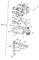
- the device shown in Figure 1 has a turntable compartment 2 with four compartment doors 7, which used to eject a formed Stack S about a vertical axis, for example pneumatically are pivotable.
- pneumatic lines 15 and in each case a pivot drive 44 is provided.
- the turntable compartment 2 is mounted on a turntable 9, the angle feet 23 or other suitable fasteners a rotary ring 11 is attached.
- This rotary ring 11 is with a motor 12 which rotates via a toothed belt wheel 14 and a toothed belt 13 is connected to the rotary ring 11.
- the Receiving a driver 18 of an ejection device 17th serves.
- a flexible conduit 16 is provided for the pneumatic lines 15 to the turntable 9 is a flexible conduit 16 is provided. Of course can through this duct 16 and other lines be passed.
- a lift 3 is integrated.
- This lift 3 has two layer lift parts 3a and 3b, which are arranged with respect to the ejection groove 10 substantially mirror-symmetrically.
- the lift parts 3a and 3b are made substantially of equal parts and operate substantially synchronously with each other.
- the lift parts 3a and 3b each have a lift plate 8, which are shown in Figure 1 with dashed lines. In the arrangement shown, these lift plates 8 are applied to the turntable 9.
- the lift plates 8 are each mounted on a lift guide 6 and vertically movable on this.
- the lift plates 8 are preferably moved vertically along the lift guide 6 by means of pneumatic cylinders 45, both lift plates 8 being independent of each other. Preferably, both lift plates 8 are moved synchronously with each other.
- the lift plates 8 can be raised in the position shown in Fig. 1 position and moved back to the original position.
- the lift plates 8 can be raised at most to the position of the press flaps 4, or the stroke is deliberately reduced to a predetermined level for the purpose of picking up falling layers.
- servomotors could be used to generate the drive.
- the two lift plates 8 are arranged at a distance from each other, so that there is a passage between them and the aforementioned ejection groove 10 is arranged freely between these layer plates 8.
- the two lift parts 3a and 3b each have a press flap 4, which each with a pneumatic cylinder 5 horizontally are movable.
- the press flaps 4 each shown in a retracted position. In this Layers L can be inserted into the turntable compartment 2 freely from above become. In another advanced position they protrude Press flaps 4 at least partially in the turntable compartment 2 inside.
- These movements are preferably carried out with the mentioned Pneumatic cylinders 5, but here is another Drive, for example with a servomotor conceivable.
- For Format settings of the turntable compartment 2 in the direction of Outlet groove motors 28 are provided, which are not closer Gear referred to the drive movement by means of waves 29, which are formed as a spindle, on the compartment flaps 7 transmitted.
- the loading of the turntable compartment 2 with layers L is carried out according to FIG. 3 with the aid of a layer compartment 32 and forks 34 of Figure 3 is located in the ply 32 a position L.
- Die Fork 34 is closed here and keeps the position L in the shown Position.
- the fork 34 can be opened so that the layer L falls from above into the turntable compartment 2.
- aforementioned ejection device 17th To eject a complete stack S from the turntable compartment 2 is the aforementioned ejection device 17th intended.
- This has according to Figure 2 on a carrier 19, attached to the underside of the turntable 9 at this is and runs parallel to the ejection groove 10.
- the carrier 19 On the bottom the carrier 19 are guide rods 24 or the like Guiding means provided on which a carriage 25 is mounted is horizontal in the directions of the double arrow 26 is movable.
- a pneumatic cylinder 21st or another suitable drive means for example a servomotor attached.
- this pneumatic cylinder 21 is the driver 18, which is rod-shaped, vertical method.
- For horizontal movement of the carriage 25th is another drive 20, for example a servomotor, intended.
- the horizontal movement can also be pneumatic respectively.
- connection of the pneumatic cylinder 21 to the not shown here pneumatic line is a suitable Connection means 22 at the lower end of the pneumatic cylinder 21st arranged.
- the driver 18 can thus simultaneously in the Directions of the double arrow 26 moves horizontally and simultaneously be moved vertically.
- a control for controlling the drives is of course a control, not shown here intended.
- FIG. 4a shows an initial state in which the Turntable compartment 2 is still empty.
- the fork 34 of the sheet tray 32 is closed.
- Newly supplied printed products 33 are in the Layer hold 32 and finally form a layer L.
- the two press flaps 4 are in the retracted Position so that the turntable compartment 2 is open at the top.
- the both lift plates 8 are in a raised position.
- the printed products 33 of the layer L each have one Fold F up. These folds F are all on top of each other and thus on the same side of the sheet tray 32nd
- FIG. 4b shows a completely formed layer L which is in the Layer pocket 32 was formed.
- the lift plates 8 are now moved down, the Position L led to the flaps 7 of the turntable compartment 2 and is aligned. Simultaneously with the closing of the fork 34, the press flaps 4 are in the position shown in Figure 4d hazards. In this position, the press flaps 4 protrude at least partially in the turntable compartment 2 inside.
- the Position L is now raised in the direction of arrows 37 and on pressed the retracted press flaps 4.
- the two Lift plates 8 are synchronized by appropriate Actuation of the two lift parts 3a and 3b raised.
- the Folds F are here in Figure 4d in the left lift plate. 8 fully supported and thus these folds F completely and be pressed effectively.
- the lift plate 8 extends thus also in the area of the folds F.
- the layer L is pressed, then the compressed layer L ' moved down according to Figure 4e. At the same time the Pressing flaps 4 moves in the retracted position. The Fork 34 remains closed, so at the same time in the ply 32, another layer L can be formed. The location L 'is rotated by turning the table 9 by 180 °. Is in the ply 32 formed a new layer L, the above-mentioned Process repeated. When pressing this, however, already two crosswise laid layers L pressed. The process can be repeated several times, so finally a Stack S is present, consisting of several crosswise deposited L locations exists. The lifting of the lift plates 8 for pressing is adjusted according to the height of the formed stack S.
- FIGs 5a and 5b show schematically the ejection of a formed stack S.
- This stack S can as mentioned consist of several layers L deposited crosswise.
- the driver 18 When making of the stack S is the driver 18 completely below the table 9, as in Figure 5b with dashed Lines is indicated.
- the driver After completion of the last rotation of the table 9 by 180 °, before ejecting the stack S, the driver is 18 format dependent immediately left of stack formed S raised in the direction 39. The lifting height may depend on the height of the stack S.
- the driver 18 is in the direction 38 moves.
- the raised driver 18 is here on Stack S and pushes this according to Fig. 5a from the left to right.
- FIG. 5b shows a ejected stack S ', which in the direction of arrow 43 too a means of transport, not shown here is moved.
Landscapes
- Engineering & Computer Science (AREA)
- Mechanical Engineering (AREA)
- Pile Receivers (AREA)
Priority Applications (5)
| Application Number | Priority Date | Filing Date | Title |
|---|---|---|---|
| EP04405283A EP1593633B1 (fr) | 2004-05-05 | 2004-05-05 | Dispositif pour empiler des articles imprimés |
| DK04405283T DK1593633T3 (da) | 2004-05-05 | 2004-05-05 | Indretning til dannelse af stabler af trykte produkter |
| DE502004008262T DE502004008262D1 (de) | 2004-05-05 | 2004-05-05 | Vorrichtung zum Bilden von Stapeln aus Druckprodukten |
| US11/121,126 US7654789B2 (en) | 2004-05-05 | 2005-05-04 | Apparatus for forming stacks with print products with ejection groove and lifting plates |
| JP2005135398A JP4948782B2 (ja) | 2004-05-05 | 2005-05-06 | 印刷物の積重ね体を形成するための装置 |
Applications Claiming Priority (1)
| Application Number | Priority Date | Filing Date | Title |
|---|---|---|---|
| EP04405283A EP1593633B1 (fr) | 2004-05-05 | 2004-05-05 | Dispositif pour empiler des articles imprimés |
Publications (2)
| Publication Number | Publication Date |
|---|---|
| EP1593633A1 true EP1593633A1 (fr) | 2005-11-09 |
| EP1593633B1 EP1593633B1 (fr) | 2008-10-15 |
Family
ID=34932093
Family Applications (1)
| Application Number | Title | Priority Date | Filing Date |
|---|---|---|---|
| EP04405283A Expired - Lifetime EP1593633B1 (fr) | 2004-05-05 | 2004-05-05 | Dispositif pour empiler des articles imprimés |
Country Status (5)
| Country | Link |
|---|---|
| US (1) | US7654789B2 (fr) |
| EP (1) | EP1593633B1 (fr) |
| JP (1) | JP4948782B2 (fr) |
| DE (1) | DE502004008262D1 (fr) |
| DK (1) | DK1593633T3 (fr) |
Cited By (2)
| Publication number | Priority date | Publication date | Assignee | Title |
|---|---|---|---|---|
| EP2368826A1 (fr) | 2010-03-25 | 2011-09-28 | Müller Martini Holding AG | Procédé et dispositif destinés à former des paquets dans un dispositif de formation de paquets |
| EP2457858A1 (fr) | 2010-11-30 | 2012-05-30 | Müller Martini Holding AG | Dispositif et méthode pour la formation de paquets de produits imprimés |
Families Citing this family (4)
| Publication number | Priority date | Publication date | Assignee | Title |
|---|---|---|---|---|
| EP2133301B1 (fr) * | 2008-05-23 | 2011-06-29 | Ferag AG | Table élévatrice rotative |
| EP2192067B1 (fr) * | 2008-11-28 | 2013-09-18 | Müller Martini Holding AG | Dispositif d'empilement pour produits d'impression |
| US10076815B2 (en) | 2015-04-07 | 2018-09-18 | Canon Kabushiki Kaisha | Parts supply apparatus, parts supply method and robot system |
| KR102841955B1 (ko) * | 2023-10-20 | 2025-08-04 | 팩컴코리아(주) | 책자 형태의 인쇄 제품을 일정량씩 적재 후 방향 전환 시키는 정렬장치 |
Citations (5)
| Publication number | Priority date | Publication date | Assignee | Title |
|---|---|---|---|---|
| US3643816A (en) * | 1970-05-25 | 1972-02-22 | Weber & Co Inc H G | Stacker for bags and the like |
| EP0153983A1 (fr) * | 1984-01-20 | 1985-09-11 | Rima Enterprises, Inc. | Dispositif pour empiler des signatures |
| EP0180113A1 (fr) * | 1984-11-02 | 1986-05-07 | Werner H. K. Peters Maschinenfabrik GmbH | Appareil d'empilage de formats |
| DE3808621A1 (de) * | 1988-03-15 | 1989-09-28 | Siemens Ag | Stapelfach fuer blattfoermige aufzeichnungstraeger in einer druckeinrichtung |
| EP1167261A1 (fr) * | 2000-06-30 | 2002-01-02 | Segbert GmbH & Co. Kommanditgesellschaft | Dispositif pour former et aligner des paquets de produits d'imprimerie mobiles empilés |
Family Cites Families (19)
| Publication number | Priority date | Publication date | Assignee | Title |
|---|---|---|---|---|
| US3362707A (en) * | 1964-11-27 | 1968-01-09 | Ahlstroem Oy | Auxiliary stack holder |
| US3381829A (en) * | 1966-03-22 | 1968-05-07 | Towlsaver Inc | Sheet stacking machine |
| JPS5427018Y2 (fr) * | 1975-10-16 | 1979-09-04 | ||
| US4030621A (en) * | 1976-01-08 | 1977-06-21 | R. R. Donnelley & Sons Company | Compensating stacker for magazines |
| US4354787A (en) * | 1980-09-02 | 1982-10-19 | Photomatrix Corp. | Microfiche collating stacker |
| GB8408163D0 (en) * | 1984-03-29 | 1984-05-10 | Cadbury Typhoo Ltd | Production of tea bags &c |
| EP0309745B2 (fr) * | 1987-10-02 | 1995-06-28 | Ferag AG | Dispositif pour empiler des articles imprimés arrivant de façon continue en formation imbriquée |
| DE3742787A1 (de) * | 1987-12-17 | 1989-06-29 | Sesto Palamides | Verfahren und vorrichtung zum verpacken von druckerzeugnissen |
| US5092236A (en) * | 1990-06-06 | 1992-03-03 | Quipp Systems, Inc. | Method and apparatus for stacking, aligning and compressing signatures |
| WO1993001060A1 (fr) * | 1991-07-04 | 1993-01-21 | Gunze Limited | Systeme assurant la disposition de feuilles de papier imprimees |
| JP2628954B2 (ja) * | 1991-12-26 | 1997-07-09 | 忠男 宇野 | シート束集積装置 |
| DE4328604C2 (de) * | 1993-08-25 | 1995-12-07 | Gaemmerler Hagen | Drehbare Stapelkammer in einem Kreuzleger für Druckprodukte |
| DE4408780A1 (de) * | 1994-03-15 | 1995-09-21 | Gunter Gaemmerler | Verfahren zum Stapeln von Flächengebilden |
| DE4427703A1 (de) * | 1994-08-04 | 1996-02-15 | Hagen Gaemmerler | Vorrichtung zum Entnehmen eines Stapels von flächenähnlichen Produkten aus einer Sammelstelle |
| JPH08306765A (ja) * | 1995-04-28 | 1996-11-22 | Advantest Corp | ハンドラ装置用トレイ装着台 |
| DE19615009B4 (de) * | 1996-04-16 | 2005-09-29 | Smb Schwede Maschinenbau Gmbh | Kreuzleger mit Umreifungsvorrichtung |
| DE59707093D1 (de) | 1996-09-11 | 2002-05-29 | Grapha Holding Ag | Vorrichtung zum Ausstossen gestapelter Druckbogen |
| US6149149A (en) * | 1997-08-04 | 2000-11-21 | Gammerler Ag | Cross stacker |
| US6120239A (en) * | 1997-08-29 | 2000-09-19 | Roskam; Mervin W. | Compensating stacking machine and method of using same |
-
2004
- 2004-05-05 EP EP04405283A patent/EP1593633B1/fr not_active Expired - Lifetime
- 2004-05-05 DE DE502004008262T patent/DE502004008262D1/de not_active Expired - Lifetime
- 2004-05-05 DK DK04405283T patent/DK1593633T3/da active
-
2005
- 2005-05-04 US US11/121,126 patent/US7654789B2/en not_active Expired - Lifetime
- 2005-05-06 JP JP2005135398A patent/JP4948782B2/ja not_active Expired - Fee Related
Patent Citations (5)
| Publication number | Priority date | Publication date | Assignee | Title |
|---|---|---|---|---|
| US3643816A (en) * | 1970-05-25 | 1972-02-22 | Weber & Co Inc H G | Stacker for bags and the like |
| EP0153983A1 (fr) * | 1984-01-20 | 1985-09-11 | Rima Enterprises, Inc. | Dispositif pour empiler des signatures |
| EP0180113A1 (fr) * | 1984-11-02 | 1986-05-07 | Werner H. K. Peters Maschinenfabrik GmbH | Appareil d'empilage de formats |
| DE3808621A1 (de) * | 1988-03-15 | 1989-09-28 | Siemens Ag | Stapelfach fuer blattfoermige aufzeichnungstraeger in einer druckeinrichtung |
| EP1167261A1 (fr) * | 2000-06-30 | 2002-01-02 | Segbert GmbH & Co. Kommanditgesellschaft | Dispositif pour former et aligner des paquets de produits d'imprimerie mobiles empilés |
Cited By (3)
| Publication number | Priority date | Publication date | Assignee | Title |
|---|---|---|---|---|
| EP2368826A1 (fr) | 2010-03-25 | 2011-09-28 | Müller Martini Holding AG | Procédé et dispositif destinés à former des paquets dans un dispositif de formation de paquets |
| US8794134B2 (en) | 2010-03-25 | 2014-08-05 | Mueller Martini Holding Ag | Method and apparatus for forming bundles in a bundle former |
| EP2457858A1 (fr) | 2010-11-30 | 2012-05-30 | Müller Martini Holding AG | Dispositif et méthode pour la formation de paquets de produits imprimés |
Also Published As
| Publication number | Publication date |
|---|---|
| JP2005320169A (ja) | 2005-11-17 |
| US7654789B2 (en) | 2010-02-02 |
| DE502004008262D1 (de) | 2008-11-27 |
| JP4948782B2 (ja) | 2012-06-06 |
| EP1593633B1 (fr) | 2008-10-15 |
| DK1593633T3 (da) | 2009-02-02 |
| US20050281655A1 (en) | 2005-12-22 |
Similar Documents
| Publication | Publication Date | Title |
|---|---|---|
| DE102020111022A1 (de) | Handhabungsvorrichtung für Produktstapel | |
| EP1477445A1 (fr) | Dispositif pour charger des brochures sur une machine a trois couteaux | |
| DE102011013983A1 (de) | Ein Stapler, ein Stapelsystem oder eine Stapelbaugruppe und ein Verfahren zum Stapeln | |
| EP2457858A1 (fr) | Dispositif et méthode pour la formation de paquets de produits imprimés | |
| EP2147881A2 (fr) | Dispositif pour déposer des produits plats | |
| EP0981480B1 (fr) | Procede et dispositif destines en particulier a l'emballage d'objets plats | |
| DE3423948C2 (fr) | ||
| EP0059746B1 (fr) | Dispositif pour l'empilage de produits plans imbriques | |
| EP0309745B1 (fr) | Dispositif pour empiler des articles imprimés arrivant de façon continue en formation imbriquée | |
| EP1593633B1 (fr) | Dispositif pour empiler des articles imprimés | |
| EP0591099B1 (fr) | Procédé et dispositif pour fabriquer des piles de produits en papier liées | |
| CH679924A5 (fr) | ||
| EP1439143A1 (fr) | Méthode et dispositif pour former des piles de produits d'imprimerie, comprenant une feuille additionnelle | |
| DE102019128026A1 (de) | Zentriereinrichtung, Verfahren zum Anpassen einer Zentriereinrichtung sowie Stapel- und/oder Palettiervorrichtung | |
| DE3141075C2 (de) | Zuführeinrichtung für Blechstreifenstapel zur Zufuhr zu einem Stanzautomaten | |
| DE3439908A1 (de) | Maschinen zum auffalten von kartons aus ebenen zuschnitten | |
| EP2062838B1 (fr) | Méthode et dispositif destinés au retrait de feuilles intermédiaires entre produits palettisés | |
| DE102015113650A1 (de) | Vorrichtung zum Aufstecken von Ventilsäcken und Verfahren zum Betreiben | |
| DE2756473A1 (de) | Vorrichtung zum einfuellen von papierstapeln in schachteln | |
| EP3765370B1 (fr) | Dispositif de déplacement d'un moyen de rembourrage dans un récipient de transport et procédé de fonctionnement d'un tel dispositif | |
| EP0810174B1 (fr) | Dispositif pour l'empilage vertical de produits imprimés | |
| EP3694798A1 (fr) | Margeur destiné à une machine permettant le traitement d'un matériau sous forme de feuilles tel que du papier, du carton-pâte ou des films | |
| DE19841907C1 (de) | Verfahren und Vorrichtung zum Etikettieren von Blumentöpfen | |
| DE2111562C3 (de) | Vorrichtung zum Auslegen von geschnittenen und gefalzten Druckerzeugnissen | |
| DE4210749C2 (de) | Vorrichtung zum Einbringen von Beutelpackungen in einen Sammelbehälter |
Legal Events
| Date | Code | Title | Description |
|---|---|---|---|
| PUAI | Public reference made under article 153(3) epc to a published international application that has entered the european phase |
Free format text: ORIGINAL CODE: 0009012 |
|
| AK | Designated contracting states |
Kind code of ref document: A1 Designated state(s): AT BE BG CH CY CZ DE DK EE ES FI FR GB GR HU IE IT LI LU MC NL PL PT RO SE SI SK TR |
|
| AX | Request for extension of the european patent |
Extension state: AL HR LT LV MK |
|
| 17P | Request for examination filed |
Effective date: 20060317 |
|
| AKX | Designation fees paid |
Designated state(s): CH DE DK FR GB IT LI |
|
| 17Q | First examination report despatched |
Effective date: 20061019 |
|
| GRAP | Despatch of communication of intention to grant a patent |
Free format text: ORIGINAL CODE: EPIDOSNIGR1 |
|
| GRAS | Grant fee paid |
Free format text: ORIGINAL CODE: EPIDOSNIGR3 |
|
| GRAA | (expected) grant |
Free format text: ORIGINAL CODE: 0009210 |
|
| AK | Designated contracting states |
Kind code of ref document: B1 Designated state(s): CH DE DK FR GB IT LI |
|
| REG | Reference to a national code |
Ref country code: CH Ref legal event code: EP Ref country code: GB Ref legal event code: FG4D Free format text: NOT ENGLISH |
|
| REF | Corresponds to: |
Ref document number: 502004008262 Country of ref document: DE Date of ref document: 20081127 Kind code of ref document: P |
|
| REG | Reference to a national code |
Ref country code: DK Ref legal event code: T3 |
|
| PLBE | No opposition filed within time limit |
Free format text: ORIGINAL CODE: 0009261 |
|
| STAA | Information on the status of an ep patent application or granted ep patent |
Free format text: STATUS: NO OPPOSITION FILED WITHIN TIME LIMIT |
|
| 26N | No opposition filed |
Effective date: 20090716 |
|
| REG | Reference to a national code |
Ref country code: FR Ref legal event code: PLFP Year of fee payment: 13 |
|
| REG | Reference to a national code |
Ref country code: FR Ref legal event code: PLFP Year of fee payment: 14 |
|
| PGFP | Annual fee paid to national office [announced via postgrant information from national office to epo] |
Ref country code: DK Payment date: 20170525 Year of fee payment: 14 Ref country code: GB Payment date: 20170525 Year of fee payment: 14 Ref country code: FR Payment date: 20170525 Year of fee payment: 14 |
|
| REG | Reference to a national code |
Ref country code: DK Ref legal event code: EBP Effective date: 20180531 |
|
| GBPC | Gb: european patent ceased through non-payment of renewal fee |
Effective date: 20180505 |
|
| PG25 | Lapsed in a contracting state [announced via postgrant information from national office to epo] |
Ref country code: GB Free format text: LAPSE BECAUSE OF NON-PAYMENT OF DUE FEES Effective date: 20180505 Ref country code: FR Free format text: LAPSE BECAUSE OF NON-PAYMENT OF DUE FEES Effective date: 20180531 |
|
| PG25 | Lapsed in a contracting state [announced via postgrant information from national office to epo] |
Ref country code: DK Free format text: LAPSE BECAUSE OF NON-PAYMENT OF DUE FEES Effective date: 20180531 |
|
| PGFP | Annual fee paid to national office [announced via postgrant information from national office to epo] |
Ref country code: CH Payment date: 20190823 Year of fee payment: 16 |
|
| PG25 | Lapsed in a contracting state [announced via postgrant information from national office to epo] |
Ref country code: LI Free format text: LAPSE BECAUSE OF NON-PAYMENT OF DUE FEES Effective date: 20200531 Ref country code: CH Free format text: LAPSE BECAUSE OF NON-PAYMENT OF DUE FEES Effective date: 20200531 |
|
| PGFP | Annual fee paid to national office [announced via postgrant information from national office to epo] |
Ref country code: IT Payment date: 20220531 Year of fee payment: 19 |
|
| PGFP | Annual fee paid to national office [announced via postgrant information from national office to epo] |
Ref country code: DE Payment date: 20230525 Year of fee payment: 20 |
|
| PG25 | Lapsed in a contracting state [announced via postgrant information from national office to epo] |
Ref country code: IT Free format text: LAPSE BECAUSE OF NON-PAYMENT OF DUE FEES Effective date: 20230505 |
|
| REG | Reference to a national code |
Ref country code: DE Ref legal event code: R071 Ref document number: 502004008262 Country of ref document: DE |