EP1593781A2 - Dispositif pour la fixation détachable à une structure de support. - Google Patents
Dispositif pour la fixation détachable à une structure de support. Download PDFInfo
- Publication number
- EP1593781A2 EP1593781A2 EP05103659A EP05103659A EP1593781A2 EP 1593781 A2 EP1593781 A2 EP 1593781A2 EP 05103659 A EP05103659 A EP 05103659A EP 05103659 A EP05103659 A EP 05103659A EP 1593781 A2 EP1593781 A2 EP 1593781A2
- Authority
- EP
- European Patent Office
- Prior art keywords
- component
- support structure
- mast
- frame
- cam mechanism
- Prior art date
- Legal status (The legal status is an assumption and is not a legal conclusion. Google has not performed a legal analysis and makes no representation as to the accuracy of the status listed.)
- Granted
Links
Images




Classifications
-
- E—FIXED CONSTRUCTIONS
- E02—HYDRAULIC ENGINEERING; FOUNDATIONS; SOIL SHIFTING
- E02F—DREDGING; SOIL-SHIFTING
- E02F3/00—Dredgers; Soil-shifting machines
- E02F3/04—Dredgers; Soil-shifting machines mechanically-driven
- E02F3/627—Devices to connect beams or arms to tractors or similar self-propelled machines, e.g. drives therefor
-
- E—FIXED CONSTRUCTIONS
- E02—HYDRAULIC ENGINEERING; FOUNDATIONS; SOIL SHIFTING
- E02F—DREDGING; SOIL-SHIFTING
- E02F3/00—Dredgers; Soil-shifting machines
- E02F3/04—Dredgers; Soil-shifting machines mechanically-driven
- E02F3/627—Devices to connect beams or arms to tractors or similar self-propelled machines, e.g. drives therefor
- E02F3/6273—Devices to connect beams or arms to tractors or similar self-propelled machines, e.g. drives therefor using legs to support the beams or arms on the ground during the connecting process
Definitions
- the invention relates to a device for releasably attaching to a support structure, in particular a charger device.
- the object underlying the invention is seen therein to provide a charger device which is simpler and faster on a tractor or can be dismantled. Furthermore, the invention has the object, a Charger device to provide, which has fewer components and easier to operate from the driver's seat.
- a charger device and a mechanism for mounting and dismounting the loading device to a tractor proposed.
- the driver needs his driver's seat not leave to build or dismantle the charger device, with the exception of connecting or disconnecting hydraulic Cables for the supply of hydraulic cylinders.
- Maintenance and other measures affecting the charger device or affecting the tug, can be done more easily be without any additional time to attach or disconnect the Loading device must be applied.
- the charger device essentially allows one automatic attachment or dismantling of the tractor, it points opposite earlier devices a small number of components. With the present invention is a driver in the Location, the attachment and removal of the charger device from the tractor easier and with less effort to control.
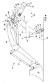
- FIG. 1 shows a side view of a charger device 20 shown with a support structure, such as a frame 22nd an agricultural tractor (not shown), connected is.
- a support structure such as a frame 22nd an agricultural tractor (not shown)
- the charger device 20 a first, second and third component, which functionally interconnected and as mast 24, rocker 26 and strut 28 are formed.
- the frame 22 and the charger device 20 has an attachment assembly 30.
- a hydraulic cylinder 32 as in FIGS. 1 to 4 shown, has various hydraulic connections (not shown) and is at a first end 34 with the Swingarm 26 connected. At a second end 36 is the Cylinder 32 with both the rocker 26 and with a Tool, such as a blade 38, connected such that the Driver of the tractor a desired movement can perform. This can also be a different tool than the Blade 38 in conjunction with the described Charger device 20 are operated.
- the charger device 20 is with the frame 22 at respective front and rear Frame areas 40, 42 connected. Since the charger device 20 and the frame portions 40, 42 to which it is connected, arranged symmetrically to a longitudinal axis "X" of the tractor are, only the left side of the front and rear Frame portions 40, 42 of the frame 22 described in more detail.
- FIG. 1 shows how the charger device 20 in FIG operated in a first mode, in which this completely with connected to the frame 22 of the tractor.
- the mast 24 of the charger device 20 has an upper and a lower end region 44, 46. At its bottom End portion 46, the mast 24 is a substantially open trained Ausschalung on, so that a receiving area 48 formed with the rear frame portion 42 of Frame 22 can be brought into connection (see Figures 1 to 4).
- the rear frame portion 42 the frame 22 is partially formed in the form of a tube 50.
- the tube 50 has a Mounting plate 54 for attachment to the body of the tractor on.
- the tube 50 alternately rising and falling areas 58, 60.
- the tube 50 furthermore, a cylinder bolt 62 attached thereto.
- the strut 28 is pivotally connected to the mast 24 at a point "d" mounted and extends laterally from it.
- the strut 28 comprises a ground engaging part, which may be referred to, for example, as foot-like part 66 is formed.
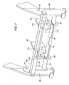
- the foot-like part 66 comprises at least one upper and lower connecting element 68, 70, which are arranged spaced from each other and to Connection to the front frame portion 40 of the frame 22nd serve, as shown in Figures 1 to 4 and 7.
- the lower connecting element 70 has a round and upper connecting element 68 has a rectangular cross-section.
- the lower Connecting element 70 is formed as part of a bracket 78.
- the bracket 78 is pivotally attached to the foot-like portion 66 at one Point "g" mounted, allowing a movement relative to the front Frame part 40 of the frame 22 during attachment and removal of the Charger device 20 is enabled.
- bottom link 70 with a pair of laterally opposite and upwardly directed tabs 80 connected.
- the strut 28th a useful clamping force on the front frame area 40 of the frame 22.
- the Car drivers generally be sure that the Charger device 20 even under the heaviest working conditions not released from the tractor.
- a is Cam mechanism 82 pivots about this point with the strut 28 connected.
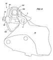
- the cam mechanism 82 includes a body 84 with an actuating element, which exemplifies a handle 86, for rotating the body 84 relative to the point "h” in FIG Forward or backward direction, is formed as is shown in detail in Figures 5 and 6.
- the body 84 further includes a housing 88 as in FIG. 5 shown, which has an extendable part, for example a bolt 90, receives.
- the bolt 90 is relative to the Housing 88 adjustable positionable to make contact with an arcuate contact surface 92 on the mast 24 produce or to avoid.
- the cam mechanism 82 is in communication with a Arret réellesarm 94 shown, both of the driver's seat can be reached from the tractor.
- the locking arm 94 is formed for example in the form of a leaf spring.
- the Arret réellesarm 94 is fixed with strut 28 is pinned at points "i" and at one point "j" adjustable in the body 84 of the cam mechanism 82nd fitted, wherein the fitting takes place by means of a nose 96, which extends from a side surface 98 of the body 84.
- the cam mechanism 82 is in Connection with a spring 100.
- the spring 100 is in one Interior 102 of the (cam) body 84 housed and with the Strut 28 connected at a point "k" to hold one Positioning relative to the point "h” in reverse or Forward direction support.
- the bolt 90 is in one to the contact surface 92 abutting position, when the handle 86 to is twisted behind the point "h".
- a position is characteristic of a first mode in which the Charger device 20 completely with the frame 22 of the Tug is engaged, where, as already mentioned, the Mast 24 in the rear frame portion 42 of the frame 22nd fitted and the foot-like portion 66 of the strut 28 in the front frame portion 40 of the frame 22 is clamped.
- the driver can determine the position of the driver Adjust the head of the bolt 90 so that it is in the Essentially with the contact surface 92 of the mast 24 in engagement occurs.
- the possibility of the length of the bolt 90 in the housing 88th to be able to adjust, allows the driver, the Adjusting the position of the mast 24 relative to the strut 28.
- a Such possibility is in the cases of advantage in which Cause wear and tear, be it between the foot-like part 66 and the front frame part 40 of the frame 22 or the rear frame part 42 of the frame 22 and the Receiving area 48 or in the leadership of the bolt 90 on the Bearing surface 92, that is the holder of the charger device on the frame 22 can solve.
- FIG. 1 it can be seen that the first mode is present when (A) the bolt 90 substantially with the contact surface 92 of the Mastes 24 is in contact and (b) the receiving area 48 of the Mast 24 completely on the rear frame portion 42 of Frame 22 rests. It is intended that the driver the locking arm 94 in the position shown in Figure 1 brings about the position of the body 84 of the cam mechanism 82nd and thus the bolt 90 to hold.
- FIGS. 2 to 4 show a second mode which relates to the removal of the charger device 20 from the tractor.
- a first Step for disassembling the charger device 20 of the locking arm 94 is solved by this at its handle 104 (see FIG 5) pulled outward from its fitting with the nose 96 becomes.
- the handle 86 can be completely in Forward direction relative to the point "h" to be moved.
- These Forward movement of the handle 86 rotates the body 84 of the Cam mechanism 82 such that the bolt 90 from his Contact position with the contact surface 92 of the mast 24 brought becomes.
- a End portion 106 of the body 84 of the cam mechanism 82 in a Stop position with the contact surface 92 of the mast 24th brought.
- Step reaches when the driver the lifting cylinder 64th fully extended.
- the foot-like part 66 is in an im Substantially vertical position relative to the frame 22 and to Soil surface brought.
- the receiving area 48 of the dissolves Mast 24 from the rear frame portion 42 of the frame 22 as it is shown in more detail in FIG.
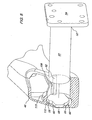
- Receiving portion 48 of the mast 24 has a first and a second groove 108, 110.
- the first groove 108 extends from the point “1" to to the point “m” and has a surface with which the attached cylinder pin 62 comes into contact when the mast 24 mounted on the rear frame portion 42 of the frame 22 is. Such a contact is particularly in Figure 10 in Point "1" shown.
- Fig. 11 shows a position between the points "l" and "m”, such a position occurring when the charger device 20 is dismantled from the frame 22. It will clear that the patch cylinder pin 62 is not on a End point of the groove 108 is present. As a result, the Mast 24 relative to the rear frame part 42 of the frame 22nd move.
- the second groove 110 provides clearance for the rising Area 58, so that it is movable when the Charger device 20 to / from the rear frame portion 42 of Frame 22 is grown / dismantled. Furthermore, it is for One skilled in the art will recognize that a contact between the first groove 108 and the attached cylinder pin 62 serves, essentially over-turning of the mast 24 away from the rear frame portion 42 of the frame 22 to avoid. In addition, such overwinding is also characterized avoided, as shown in Figure 10 that the rising area 58 against an inner segment 113 of the Recording area 48 strikes.
Landscapes
- Engineering & Computer Science (AREA)
- Mechanical Engineering (AREA)
- Mining & Mineral Resources (AREA)
- Civil Engineering (AREA)
- General Engineering & Computer Science (AREA)
- Structural Engineering (AREA)
- Agricultural Machines (AREA)
- Fittings On The Vehicle Exterior For Carrying Loads, And Devices For Holding Or Mounting Articles (AREA)
Applications Claiming Priority (2)
| Application Number | Priority Date | Filing Date | Title |
|---|---|---|---|
| US10/840,982 US7281890B2 (en) | 2004-05-07 | 2004-05-07 | Arrangement for the attachment or detachment of an assembly to a base structure |
| US840982 | 2004-05-07 |
Publications (3)
| Publication Number | Publication Date |
|---|---|
| EP1593781A2 true EP1593781A2 (fr) | 2005-11-09 |
| EP1593781A3 EP1593781A3 (fr) | 2006-12-06 |
| EP1593781B1 EP1593781B1 (fr) | 2010-04-07 |
Family
ID=34939650
Family Applications (1)
| Application Number | Title | Priority Date | Filing Date |
|---|---|---|---|
| EP05103659A Expired - Lifetime EP1593781B1 (fr) | 2004-05-07 | 2005-05-03 | Combinaison d'un dispositif chargeur et d'une structure de support. |
Country Status (3)
| Country | Link |
|---|---|
| US (1) | US7281890B2 (fr) |
| EP (1) | EP1593781B1 (fr) |
| DE (1) | DE502005009342D1 (fr) |
Cited By (1)
| Publication number | Priority date | Publication date | Assignee | Title |
|---|---|---|---|---|
| EP2829662A1 (fr) | 2013-07-25 | 2015-01-28 | Deere & Company | Système de chargeur frontal |
Families Citing this family (14)
| Publication number | Priority date | Publication date | Assignee | Title |
|---|---|---|---|---|
| US7578648B2 (en) * | 2007-09-28 | 2009-08-25 | Deere & Company | Front latch system for a front end loader |
| USD595746S1 (en) * | 2008-09-19 | 2009-07-07 | Yanmar Co., Ltd. | Front loader |
| USD610172S1 (en) | 2009-06-22 | 2010-02-16 | Yanmar Co., Ltd. | Front loader |
| US8287226B1 (en) | 2009-09-10 | 2012-10-16 | Westendorf Manufacturing Co., Inc. | Front end loader attachment and locking mechanism |
| USD672372S1 (en) | 2011-01-10 | 2012-12-11 | Alo Aktiebolag | Front loader for a tractor |
| USD656523S1 (en) * | 2011-07-07 | 2012-03-27 | Alo Aktiebolag | Front loader assembly |
| USD739446S1 (en) | 2011-07-08 | 2015-09-22 | Alo Aktiebolag | Front loader for a tractor |
| USD768731S1 (en) * | 2014-04-16 | 2016-10-11 | Deere & Company | Frontloader |
| USD769335S1 (en) * | 2014-04-16 | 2016-10-18 | Deere & Company | Frontloader |
| CA160237S (en) * | 2014-06-23 | 2016-01-27 | Deere & Co | Frontloader |
| USD766343S1 (en) * | 2015-05-20 | 2016-09-13 | Deere & Company | Front end final loader |
| USD807407S1 (en) * | 2016-10-28 | 2018-01-09 | Kubota Corporation | Bucket work machine for a loader |
| US10753063B2 (en) | 2017-12-27 | 2020-08-25 | Kubota Corporation | Front loader |
| US10036138B1 (en) | 2017-12-27 | 2018-07-31 | Kubota Corporation | Front loader and working machine with left and right wires |
Citations (1)
| Publication number | Priority date | Publication date | Assignee | Title |
|---|---|---|---|---|
| US5895199A (en) | 1997-08-11 | 1999-04-20 | New Holland North America, Inc. | Apparatus for coupling a front end loader to a tractor |
Family Cites Families (7)
| Publication number | Priority date | Publication date | Assignee | Title |
|---|---|---|---|---|
| DE3521240A1 (de) | 1985-06-13 | 1986-12-18 | Xaver Fendt & Co, 8952 Marktoberdorf | Befestigung eines frontladers an einem ladefahrzeug |
| JPH04110406A (ja) | 1990-08-31 | 1992-04-10 | Nkk Corp | 鉄鉱石の溶融還元設備における予備還元炉 |
| JP2526814Y2 (ja) * | 1991-03-13 | 1997-02-26 | 株式会社クボタ | 作業装置の取付構造 |
| JPH059951A (ja) | 1991-07-01 | 1993-01-19 | Kubota Corp | 車両の作業機装着装置 |
| US5387076A (en) * | 1993-08-23 | 1995-02-07 | Deere & Company | Structure for attaching a loader to a tractor |
| US5388950A (en) * | 1993-08-23 | 1995-02-14 | Deere & Company | Bumper quick-attach for tractor front-end loaders |
| JP2750264B2 (ja) | 1993-08-27 | 1998-05-13 | 株式会社クボタ | 作業機の装着装置 |
-
2004
- 2004-05-07 US US10/840,982 patent/US7281890B2/en not_active Expired - Lifetime
-
2005
- 2005-05-03 EP EP05103659A patent/EP1593781B1/fr not_active Expired - Lifetime
- 2005-05-03 DE DE502005009342T patent/DE502005009342D1/de not_active Expired - Lifetime
Patent Citations (1)
| Publication number | Priority date | Publication date | Assignee | Title |
|---|---|---|---|---|
| US5895199A (en) | 1997-08-11 | 1999-04-20 | New Holland North America, Inc. | Apparatus for coupling a front end loader to a tractor |
Cited By (3)
| Publication number | Priority date | Publication date | Assignee | Title |
|---|---|---|---|---|
| EP2829662A1 (fr) | 2013-07-25 | 2015-01-28 | Deere & Company | Système de chargeur frontal |
| DE102013214559A1 (de) | 2013-07-25 | 2015-01-29 | Deere & Company | Frontladeranordnung |
| US9234327B2 (en) | 2013-07-25 | 2016-01-12 | Deere & Company | Front loader arrangement with hook-shaped locking bar |
Also Published As
| Publication number | Publication date |
|---|---|
| US20050281659A1 (en) | 2005-12-22 |
| US7281890B2 (en) | 2007-10-16 |
| EP1593781A3 (fr) | 2006-12-06 |
| DE502005009342D1 (de) | 2010-05-20 |
| EP1593781B1 (fr) | 2010-04-07 |
Similar Documents
| Publication | Publication Date | Title |
|---|---|---|
| DE2715375C3 (de) | Stellvorrichtung für ein landwirtschaftlich nutzbares Arbeitsgerät | |
| EP2408971B1 (fr) | Dispositif de brosses de balayage interchangeable et balayeuse comportant un tel dispositif de brosses de balayage | |
| EP1593781B1 (fr) | Combinaison d'un dispositif chargeur et d'une structure de support. | |
| DE1247725B (de) | Schnellkupplung | |
| DE2948899A1 (de) | Fahrzeug mit geraete-schnellkuppler | |
| DE3022833C2 (de) | Vorrichtung zum Entwurzeln von Baumstümpfen | |
| EP1163830A1 (fr) | Appareil agricole tracté | |
| EP2829662B1 (fr) | Système de chargeur frontal | |
| EP0978592B1 (fr) | Chargeur et véhicule comprenant un chargeur | |
| DE1222726B (de) | Kupplungsvorrichtung zwischen einem Schlepper und einem an diesen anzubauenden Arbeitsgeraet | |
| DE4419051A1 (de) | Arbeitsgerät-Kuppelvorrichtung | |
| DE102008004998B4 (de) | Höhenverstellbarer Fahrzeugsitz mit einer Memory-Funktion und Verfahren zur Verstellung eines Fahrzeugsitzes | |
| DE2613718C2 (de) | An einem Schlepper anbringbare Dreipunkt-Anbauvorrichtung | |
| DE19820377C1 (de) | Arbeitsfahrzeug mit kippbarer Fahrerplattform und Kippvorrichtung | |
| EP1830006B1 (fr) | Machine de travaux de construction et procédé pour la preparation du transport de cette machine | |
| DE1218199B (de) | Hubvorrichtung fuer am Heck eines Schleppers anzubauende landwirtschaftliche Bodenbearbeitungsgeraete | |
| DE1249707B (de) | Zughakenkupplung fur Schlepper | |
| DE102005019764B4 (de) | Längsverstellbarer Kraftfahrzeugsitz | |
| DE10330382B4 (de) | Heuwerbungsmaschine | |
| DE884707C (de) | Scheibenschwenkpflug | |
| AT275942B (de) | Schnellkuppelvorrichtung zum Anbau von landwirtschaftlichen Geräten an das Dreipunktgestänge von Schleppern | |
| DE69901285T2 (de) | Geräteanschlussmechanismus und -verfahren | |
| EP0679769B1 (fr) | Dispositif pour la commande d'un élément mobile | |
| DE2308218C3 (de) | Vorrichtung zum Kuppeln eines Fahrzeuges, insbesondere eines bau- oder landwirtschaftlichen Schleoppers mit einem Gerät, Anhänger od.dgl. und/oder Anhängern miteinander | |
| DE953477C (de) | Hebevorrichtung, insbesondere fuer das Schneidwerk von Maehmaschinen |
Legal Events
| Date | Code | Title | Description |
|---|---|---|---|
| PUAI | Public reference made under article 153(3) epc to a published international application that has entered the european phase |
Free format text: ORIGINAL CODE: 0009012 |
|
| AK | Designated contracting states |
Kind code of ref document: A2 Designated state(s): AT BE BG CH CY CZ DE DK EE ES FI FR GB GR HU IE IS IT LI LT LU MC NL PL PT RO SE SI SK TR |
|
| AX | Request for extension of the european patent |
Extension state: AL BA HR LV MK YU |
|
| PUAL | Search report despatched |
Free format text: ORIGINAL CODE: 0009013 |
|
| AK | Designated contracting states |
Kind code of ref document: A3 Designated state(s): AT BE BG CH CY CZ DE DK EE ES FI FR GB GR HU IE IS IT LI LT LU MC NL PL PT RO SE SI SK TR |
|
| AX | Request for extension of the european patent |
Extension state: AL BA HR LV MK YU |
|
| 17P | Request for examination filed |
Effective date: 20070606 |
|
| AKX | Designation fees paid |
Designated state(s): DE FR GB SE |
|
| 17Q | First examination report despatched |
Effective date: 20071123 |
|
| RTI1 | Title (correction) |
Free format text: COMBINATION OF A LOADER DEVICE AND A CARRIER STRUCTURE. |
|
| GRAP | Despatch of communication of intention to grant a patent |
Free format text: ORIGINAL CODE: EPIDOSNIGR1 |
|
| GRAS | Grant fee paid |
Free format text: ORIGINAL CODE: EPIDOSNIGR3 |
|
| GRAA | (expected) grant |
Free format text: ORIGINAL CODE: 0009210 |
|
| AK | Designated contracting states |
Kind code of ref document: B1 Designated state(s): DE FR GB SE |
|
| REG | Reference to a national code |
Ref country code: GB Ref legal event code: FG4D Free format text: NOT ENGLISH |
|
| REF | Corresponds to: |
Ref document number: 502005009342 Country of ref document: DE Date of ref document: 20100520 Kind code of ref document: P |
|
| PG25 | Lapsed in a contracting state [announced via postgrant information from national office to epo] |
Ref country code: SE Free format text: LAPSE BECAUSE OF FAILURE TO SUBMIT A TRANSLATION OF THE DESCRIPTION OR TO PAY THE FEE WITHIN THE PRESCRIBED TIME-LIMIT Effective date: 20100407 |
|
| PLBE | No opposition filed within time limit |
Free format text: ORIGINAL CODE: 0009261 |
|
| STAA | Information on the status of an ep patent application or granted ep patent |
Free format text: STATUS: NO OPPOSITION FILED WITHIN TIME LIMIT |
|
| REG | Reference to a national code |
Ref country code: FR Ref legal event code: ST Effective date: 20110131 |
|
| 26N | No opposition filed |
Effective date: 20110110 |
|
| PG25 | Lapsed in a contracting state [announced via postgrant information from national office to epo] |
Ref country code: FR Free format text: LAPSE BECAUSE OF NON-PAYMENT OF DUE FEES Effective date: 20100607 |
|
| PGFP | Annual fee paid to national office [announced via postgrant information from national office to epo] |
Ref country code: DE Payment date: 20170321 Year of fee payment: 13 |
|
| REG | Reference to a national code |
Ref country code: DE Ref legal event code: R119 Ref document number: 502005009342 Country of ref document: DE |
|
| PG25 | Lapsed in a contracting state [announced via postgrant information from national office to epo] |
Ref country code: DE Free format text: LAPSE BECAUSE OF NON-PAYMENT OF DUE FEES Effective date: 20181201 |
|
| PGFP | Annual fee paid to national office [announced via postgrant information from national office to epo] |
Ref country code: GB Payment date: 20210527 Year of fee payment: 17 |
|
| GBPC | Gb: european patent ceased through non-payment of renewal fee |
Effective date: 20220503 |
|
| PG25 | Lapsed in a contracting state [announced via postgrant information from national office to epo] |
Ref country code: GB Free format text: LAPSE BECAUSE OF NON-PAYMENT OF DUE FEES Effective date: 20220503 |