EP1593809A1 - Verriegelungsvorrichtung für eine rolladenlamelle und rolladenlamelle mit einer solchen verriegelung - Google Patents
Verriegelungsvorrichtung für eine rolladenlamelle und rolladenlamelle mit einer solchen verriegelung Download PDFInfo
- Publication number
- EP1593809A1 EP1593809A1 EP05300347A EP05300347A EP1593809A1 EP 1593809 A1 EP1593809 A1 EP 1593809A1 EP 05300347 A EP05300347 A EP 05300347A EP 05300347 A EP05300347 A EP 05300347A EP 1593809 A1 EP1593809 A1 EP 1593809A1
- Authority
- EP
- European Patent Office
- Prior art keywords
- blade
- locking device
- wall
- tip
- apron
- Prior art date
- Legal status (The legal status is an assumption and is not a legal conclusion. Google has not performed a legal analysis and makes no representation as to the accuracy of the status listed.)
- Granted
Links
- 230000000903 blocking effect Effects 0.000 title claims abstract description 12
- 238000002788 crimping Methods 0.000 claims description 8
- 210000002105 tongue Anatomy 0.000 claims description 8
- 230000000694 effects Effects 0.000 claims description 5
- 238000004804 winding Methods 0.000 description 7
- 238000006073 displacement reaction Methods 0.000 description 3
- 238000005096 rolling process Methods 0.000 description 3
- 230000003993 interaction Effects 0.000 description 2
- 229920002994 synthetic fiber Polymers 0.000 description 2
- 210000001015 abdomen Anatomy 0.000 description 1
- 230000007423 decrease Effects 0.000 description 1
- 239000011521 glass Substances 0.000 description 1
- 238000009413 insulation Methods 0.000 description 1
- 238000004519 manufacturing process Methods 0.000 description 1
- 210000000056 organ Anatomy 0.000 description 1
- 238000003860 storage Methods 0.000 description 1
- 230000002747 voluntary effect Effects 0.000 description 1
Images

Classifications
-
- E—FIXED CONSTRUCTIONS
- E06—DOORS, WINDOWS, SHUTTERS, OR ROLLER BLINDS IN GENERAL; LADDERS
- E06B—FIXED OR MOVABLE CLOSURES FOR OPENINGS IN BUILDINGS, VEHICLES, FENCES OR LIKE ENCLOSURES IN GENERAL, e.g. DOORS, WINDOWS, BLINDS, GATES
- E06B9/00—Screening or protective devices for wall or similar openings, with or without operating or securing mechanisms; Closures of similar construction
- E06B9/56—Operating, guiding or securing devices or arrangements for roll-type closures; Spring drums; Tape drums; Counterweighting arrangements therefor
- E06B9/58—Guiding devices
- E06B9/581—Means to prevent or induce disengagement of shutter from side rails
-
- E—FIXED CONSTRUCTIONS
- E06—DOORS, WINDOWS, SHUTTERS, OR ROLLER BLINDS IN GENERAL; LADDERS
- E06B—FIXED OR MOVABLE CLOSURES FOR OPENINGS IN BUILDINGS, VEHICLES, FENCES OR LIKE ENCLOSURES IN GENERAL, e.g. DOORS, WINDOWS, BLINDS, GATES
- E06B9/00—Screening or protective devices for wall or similar openings, with or without operating or securing mechanisms; Closures of similar construction
- E06B9/02—Shutters, movable grilles, or other safety closing devices, e.g. against burglary
- E06B9/08—Roll-type closures
- E06B9/11—Roller shutters
- E06B9/15—Roller shutters with closing members formed of slats or the like
- E06B2009/1533—Slat connections
- E06B2009/1572—Locking means to prevent slat disengagement
-
- E—FIXED CONSTRUCTIONS
- E06—DOORS, WINDOWS, SHUTTERS, OR ROLLER BLINDS IN GENERAL; LADDERS
- E06B—FIXED OR MOVABLE CLOSURES FOR OPENINGS IN BUILDINGS, VEHICLES, FENCES OR LIKE ENCLOSURES IN GENERAL, e.g. DOORS, WINDOWS, BLINDS, GATES
- E06B9/00—Screening or protective devices for wall or similar openings, with or without operating or securing mechanisms; Closures of similar construction
- E06B9/02—Shutters, movable grilles, or other safety closing devices, e.g. against burglary
- E06B9/08—Roll-type closures
- E06B9/11—Roller shutters
- E06B9/15—Roller shutters with closing members formed of slats or the like
- E06B2009/1577—Slat end pieces used for guiding shutter
- E06B2009/1583—Slat end pieces used for guiding shutter inserted in slat cavity
Definitions
- the invention relates to a blade lock device for rolling shutter apron whose ends are brought to move in side slides.
- the invention also relates to a roller shutter deck blade comprising such a locking device.
- the present invention will find its application in the field of carpentry of the building and especially in that Shutters type roller shutter.
- such a roller shutter usually includes winding shaft which unfolds an apron consisting of a juxtaposition of blades connected to each other via articulation means.
- EP-0.690.200 it describes more particularly a locking device in the form of a locking member equipping each end of one or more blades of the apron.
- a locking member comprises a retaining lug projecting from the outer and / or inner wall of a blade in a manner adapted to cooperate with retaining means associated with the side slides.
- Such a retaining pin is otherwise subject to elastic return means in position protruding to allow its erasure in the thickness of a blade in the winding phase of the apron.
- the invention relates to a blocking device for a blade rolling shutter apron, the lateral ends of which are moved behind the scenes, characterized by the that it comes in the form of a planned tip suitable for secured to a lateral end of a blade so as to define, in the extension of the latter and in relation to at least one of the outer or inner walls of this blade, a sliding ramp extending from said outer wall or internally to the opposite inner or outer wall, said ramp terminating in an abutment rim designed to cooperate with a slide to prevent said end side of the blade to disengage from the latter under the effect a pressure exerted perpendicularly on the deck.
- the endpiece is designed capable of defining, in the extension of a lateral end of a blade and by relative to each of the outer and inner walls, such a ramp slip.
- the blocking device further comprises at least one locking member provided with a pin of blocking designed to be repelled, under the impetus of means resilient return, in projecting position relative to one outer and / or inner walls of a blade.
- the tip corresponding to the device of blocking is designed fit to be inserted into the end of a blade, between the outer and inner wall of the latter. More particularly, this tip can be set in this end of the blade by deformation thereof.
- the deformation for crimping the end of the blade comes define the extension of the slip ramp (s) of a nozzle, at the level, as appropriate, of the outer wall and / or internal of this blade.
- the advantages that flow from the present invention consist, essentially, in that the blocking device is likely to equip more easily, the end of a blade of the apron of a roller shutter.
- such a locking device is able to play its role of retaining a blade in a slide, regardless of the deformation direction imparted to said blade.
- the invention also relates to a roller shutter deck blade comprising such a locking device.
- the present invention relates to the field of shutters.
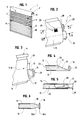
- a shutter 1 comprises, usually, a tree winding 2 can be rotated by via manual or motorized maneuvering means.
- apron 3 consisting of a juxtaposition of blades 4 interconnected by through articulation means 6. All particularly, during deployment maneuvers and folding apron 3, these blades 4 are guided at the level of their lateral ends 7, 8 by slides 9, 10.
- the present invention relates to a locking device 11 for blade 4 shutter 1, blocking device 11 having for function, when the apron 3 is deployed, to limit its deformations under the influence of a thrust that would be applied in a direction perpendicular to its plane.
- a such thrust exerted for example by a relatively violent or by a person trying to enter by burglary in a dwelling, leads to the decline of blades 4 and in some cases, to the release of the ends 7, 8 of either of these latter slides 9, 10.
- This locking device 11 comprises a tip 12 provided adapted to to be secured to a lateral end 7, 8 of a blade 4 of define, in the extension of the latter and by ratio to at least one of the outer 13 and inner 14 walls of this blade 4, a sliding ramp 15 extending from said outer wall 13 or inner wall 14 towards the wall internal opposite 14 or external 13.
- This slip ramp 15 still ends with a stop edge 16 which is designed able to cooperate with a slide 9, 10 to prevent the release side of said blade 4 of the latter.
- a locking device 11 in the form of a tip 12 defining at the end of a blade 4, with respect to each of the outer 13 and inner 14 walls of the latter, such a slip ramp 15, 15A is ending with a stop flange 16, 16A.
- These ramps slip 15, 15A are in opposition, that is to say that one is oriented towards the inner wall 14, while the other direction of the outer wall 13, knowing that the edges of stop 16, 16A are also oriented in directions opposed.
- U-shaped structures include, usually at the edge and the inner side of their outer wall 17 and inner 18, a flange 19 in which is provided a T-groove 20 for receiving a seal 21, such a flange 19 prevents, in cooperation with the abutment flange 16 of the nozzle 12, that said end 7 of the blade 4 is disengaged from this slide 9.
- the tip 12 is extended by a body endpiece 23 designed to be inserted into the end 7, 8 of a blade 4, between the outer 13 and inner 14 walls of this last. He is more particularly immobilized by crimping.
- FIGS. 2 and 7 it is visible in FIGS. 2 and 7, a cutout 24 made in one of these outer or inner walls 13, at a lateral end 7, 8 of a blade 4, so as to define one or more parts tongue 25 able to be pushed towards the inside of said blade 4 to cooperate with the tip body 23 and thus secure it by crimping the corresponding end 7, 8 of this blade 4.
- a cutout 24 made in one of these outer or inner walls 13, at a lateral end 7, 8 of a blade 4, so as to define one or more parts tongue 25 able to be pushed towards the inside of said blade 4 to cooperate with the tip body 23 and thus secure it by crimping the corresponding end 7, 8 of this blade 4.
- the cutout 24 it can be practiced in the nozzle body 23 an opening for receiving the crimping tab or tongues 25.
- the sliding ramp 15 comes in extension of the wall, depending on the case, external 13 or internal 14 of a blade 4, this beyond a junction flange 26 that includes the tip 12, in the embodiment illustrated in FIGS. 7 to 9, the ramp slip 15 at this endpiece 12 is extended to level of the outer wall 13 or inner 14 of the blade 4 by a junction ramp 27 resulting from the deformation of this wall external 13 or internal 14 at the end 7, 8 of the blade 4.
- junction ramp 27 contributes, advantageously, to solidariser the device blocking device 11 to a blade 4. More particularly, it improves tear resistance. We can still imagine that it is through this distortion of the outer wall 13 and internal 14 is ensured the crimping of a tip 12 on the end 7, 8 of a blade 4.
- such a locking device 11 can receive, in combination, a locking member 28 comprising a retaining lug 29 pushed back through return means elastic 30, in a protruding position, relative to the plane corresponding to the outer wall 13 or inner 14 to the end 7, 8 of a blade 4.
- this locking member 28 is in the form of shape of an elastically foldable tongue made integral with one end, of the tip 12, in particular of the tip body 23, and whose opposite end 32 is designed to extend beyond end 7, 8 of a blade 4 receiving the device of blocking 11 according to the invention.
- This protruding end 32 of the tongue 31 carries the pin of 29. It is more particularly folded in right angle so as to form this retaining pin 29 extending in a plane substantially perpendicular to the blade 4.
- these retaining lugs 29 may be repulsed, elastically, in an erased position compared, depending on the case, to the outer wall 13 or the inner wall 14 of a blade 4 under the effect of the superimposition of the turns described by said apron 3.
- such an organ blocking 28 may act in an opposite direction to a sliding ramp 15 and its abutment flange 16, it is possible to still imagine that they act in combination during a deformation printed in a given direction to a blade 4.
- FIGS. 7 to 10 distinguished from that corresponding to FIGS. 2 to 5, in that the locking device 11 comprises two locking members 28 arranged on both sides and acting in opposition to a sliding ramp 15 and its abutment flange 16.
- the latter intervene, in this case, when it is exerted a thrust on the outer wall 13 of a blade 4, the locking members 28 limiting the deformation of this blade 4 when printed a push in the direction opposite.
- the tip 12, more particularly, the abutment flange 16, 16A is designed convex shape on its side 33 oriented towards the bottom 34 of a slide 9, 10, this of in order not to define a sharp edge that could oppose to the displacement of the end 7, 8 of a blade 4 in such slide 9, 10.
- the locking device 11 defines at the end 7, 8 of a blade 4, a convex shaped tip, facilitating the progression of the latter along a slide 9, 10.
Landscapes
- Engineering & Computer Science (AREA)
- Structural Engineering (AREA)
- Architecture (AREA)
- Civil Engineering (AREA)
- Operating, Guiding And Securing Of Roll- Type Closing Members (AREA)
Applications Claiming Priority (2)
| Application Number | Priority Date | Filing Date | Title |
|---|---|---|---|
| FR0404755A FR2869942B1 (fr) | 2004-05-04 | 2004-05-04 | Dispositif de blocage pour lame de tablier de volet roulant et lame de tablier de volet roulant comportant un tel dispositif de blocage |
| FR0404755 | 2004-05-04 |
Publications (2)
| Publication Number | Publication Date |
|---|---|
| EP1593809A1 true EP1593809A1 (de) | 2005-11-09 |
| EP1593809B1 EP1593809B1 (de) | 2006-12-27 |
Family
ID=34942588
Family Applications (1)
| Application Number | Title | Priority Date | Filing Date |
|---|---|---|---|
| EP20050300347 Expired - Lifetime EP1593809B1 (de) | 2004-05-04 | 2005-05-02 | Verriegelungsvorrichtung für eine rolladenlamelle und rolladenlamelle mit einer solchen verriegelung |
Country Status (4)
| Country | Link |
|---|---|
| EP (1) | EP1593809B1 (de) |
| DE (1) | DE602005000370T2 (de) |
| ES (1) | ES2280074T3 (de) |
| FR (1) | FR2869942B1 (de) |
Cited By (3)
| Publication number | Priority date | Publication date | Assignee | Title |
|---|---|---|---|---|
| FR2902135A1 (fr) * | 2006-06-07 | 2007-12-14 | E V R Sarl | Embout de lame finale pour volet roulant |
| JP2016113820A (ja) * | 2014-12-16 | 2016-06-23 | 文化シヤッター株式会社 | シャッター装置のシャッターカーテン抜け止め用フック部材 |
| DE102022117412A1 (de) | 2021-08-06 | 2023-02-09 | Hörmann Kg Dissen | Sturmanker-Endstück für Rolltorprofile sowie Verwendungen desselben |
Families Citing this family (1)
| Publication number | Priority date | Publication date | Assignee | Title |
|---|---|---|---|---|
| ES2348880B1 (es) * | 2010-05-04 | 2011-10-06 | Guillermo Torres Pastor | "dispositivo de persiana enrollable, y pieza retenedora para dicho dispositivo". |
Citations (6)
| Publication number | Priority date | Publication date | Assignee | Title |
|---|---|---|---|---|
| GB265873A (en) * | 1926-09-04 | 1927-02-17 | Tomitaro Sudzki | Improvement in fire-proof shutters |
| FR1259648A (fr) * | 1960-05-24 | 1961-04-28 | Dispositif propre à empêcher de sortir de leurs guides les lames qui forment le rideau des jalousies à enroulement ou à rétraction en matière plastique, en bois et en métal | |
| DE2933154A1 (de) * | 1979-08-16 | 1981-02-26 | Matex B V | Rolltor |
| US4601320A (en) * | 1984-02-09 | 1986-07-22 | Douglas Taylor | Industrial door |
| DE3742874A1 (de) * | 1987-12-17 | 1989-06-29 | Stegmaier Maschinenbau Kg | Verfahren und einrichtung zum sichern der rolladenstaebe eines rolladens gegen axiale gegenseitige verschiebung |
| US6068040A (en) * | 1998-07-24 | 2000-05-30 | Alpine Overhead Doors, Inc. | Slat edge retainer for overhead rolling doors |
-
2004
- 2004-05-04 FR FR0404755A patent/FR2869942B1/fr not_active Expired - Fee Related
-
2005
- 2005-05-02 ES ES05300347T patent/ES2280074T3/es not_active Expired - Lifetime
- 2005-05-02 EP EP20050300347 patent/EP1593809B1/de not_active Expired - Lifetime
- 2005-05-02 DE DE602005000370T patent/DE602005000370T2/de not_active Expired - Lifetime
Patent Citations (6)
| Publication number | Priority date | Publication date | Assignee | Title |
|---|---|---|---|---|
| GB265873A (en) * | 1926-09-04 | 1927-02-17 | Tomitaro Sudzki | Improvement in fire-proof shutters |
| FR1259648A (fr) * | 1960-05-24 | 1961-04-28 | Dispositif propre à empêcher de sortir de leurs guides les lames qui forment le rideau des jalousies à enroulement ou à rétraction en matière plastique, en bois et en métal | |
| DE2933154A1 (de) * | 1979-08-16 | 1981-02-26 | Matex B V | Rolltor |
| US4601320A (en) * | 1984-02-09 | 1986-07-22 | Douglas Taylor | Industrial door |
| DE3742874A1 (de) * | 1987-12-17 | 1989-06-29 | Stegmaier Maschinenbau Kg | Verfahren und einrichtung zum sichern der rolladenstaebe eines rolladens gegen axiale gegenseitige verschiebung |
| US6068040A (en) * | 1998-07-24 | 2000-05-30 | Alpine Overhead Doors, Inc. | Slat edge retainer for overhead rolling doors |
Cited By (3)
| Publication number | Priority date | Publication date | Assignee | Title |
|---|---|---|---|---|
| FR2902135A1 (fr) * | 2006-06-07 | 2007-12-14 | E V R Sarl | Embout de lame finale pour volet roulant |
| JP2016113820A (ja) * | 2014-12-16 | 2016-06-23 | 文化シヤッター株式会社 | シャッター装置のシャッターカーテン抜け止め用フック部材 |
| DE102022117412A1 (de) | 2021-08-06 | 2023-02-09 | Hörmann Kg Dissen | Sturmanker-Endstück für Rolltorprofile sowie Verwendungen desselben |
Also Published As
| Publication number | Publication date |
|---|---|
| DE602005000370T2 (de) | 2007-07-19 |
| ES2280074T3 (es) | 2007-09-01 |
| EP1593809B1 (de) | 2006-12-27 |
| FR2869942A1 (fr) | 2005-11-11 |
| DE602005000370D1 (de) | 2007-02-08 |
| FR2869942B1 (fr) | 2006-06-16 |
Similar Documents
| Publication | Publication Date | Title |
|---|---|---|
| EP1927717A1 (de) | Führungskulisse für ein Verschluss-und/oder Verdunklungselement | |
| EP3296484A1 (de) | Längenregulierbare verstrebungsvorrichtung | |
| EP1593809B1 (de) | Verriegelungsvorrichtung für eine rolladenlamelle und rolladenlamelle mit einer solchen verriegelung | |
| EP2148040B1 (de) | Behangvorrichtung insbesondere für Verdunkelungssystem und/oder Gebäudeverschlusssystem | |
| EP4190998A1 (de) | Vorrichtung zum halten eines flügels | |
| EP3269916A1 (de) | Kastenkörper zur aufnahme eines verdunkelungselements | |
| EP0690200B1 (de) | Sperreinrichtung für Rolladen | |
| EP2690245B1 (de) | Einlauftrichter und Führungsschiene für Rollladen | |
| EP2942472B1 (de) | Verschlussvorrichtung vom typ jalousie, rollladen oder ähnliches, insbesondere für ein dachfenster | |
| EP2037077B1 (de) | Führungsschiene für eine Verdeckungsvorrichtung | |
| FR2609095A1 (fr) | Dispositif de verrouillage automatique de volets roulants | |
| EP1644607B1 (de) | Falttor und vorrichtung zur führung des torblattes | |
| EP1672163B1 (de) | Einrichtung zum Sichern der Rolladenstäbe eines Rolladen in ihrer seitlichen Führung | |
| EP0669445A1 (de) | Profilstab für einen Vorhang und Möbel mit einem derartigen Vorhang | |
| EP1972750B1 (de) | Führungsschiene eines Rollladens | |
| EP0965723B1 (de) | Rolladen für Tür, Fenster oder dergleichen | |
| EP1304784B1 (de) | Dose zur Montage entlang einem Kabel- oder Leitungskanal | |
| EP2527583B1 (de) | Verdunkelungssystem, das eine Jalousiebahn umfasst, die eine Begrenzungsvorrichtung für das Zusammenfalten der Jalousiebahn umfasst | |
| EP1927718A1 (de) | Vorrichtung zur Öffnungsbegrenzung einer Abdeckung und Verschluss- oder Sonnenschutzeinrichtung mit einer solchen Vorrichtung | |
| EP1921243A1 (de) | Schutzvorrichtung gegen Überschwemmungen | |
| FR2857040A1 (fr) | Dispositif pour l'assemblage d'elements profiles de menuiserie | |
| EP1707733A1 (de) | Rollladen mit einem System zur Feststellung der unteren Endstellung und selbstätige Verriegelung des ausgefahrenen Ladens | |
| EP2196617B1 (de) | Antihebungsvorrichtung für eine Schliessvorrichtung vom Typ Rollläden | |
| EP3059376A1 (de) | Verfahren zum einbau einer verschluss- oder sonnenschutzanlage, halterungssystem und entsprechende anlage | |
| FR3089540A1 (fr) | Coulisse anti-reflexion pour volet roulant |
Legal Events
| Date | Code | Title | Description |
|---|---|---|---|
| PUAI | Public reference made under article 153(3) epc to a published international application that has entered the european phase |
Free format text: ORIGINAL CODE: 0009012 |
|
| AK | Designated contracting states |
Kind code of ref document: A1 Designated state(s): AT BE BG CH CY CZ DE DK EE ES FI FR GB GR HU IE IS IT LI LT LU MC NL PL PT RO SE SI SK TR |
|
| AX | Request for extension of the european patent |
Extension state: AL BA HR LV MK YU |
|
| GRAP | Despatch of communication of intention to grant a patent |
Free format text: ORIGINAL CODE: EPIDOSNIGR1 |
|
| 17P | Request for examination filed |
Effective date: 20060303 |
|
| AKX | Designation fees paid |
Designated state(s): DE ES FR IT |
|
| GRAS | Grant fee paid |
Free format text: ORIGINAL CODE: EPIDOSNIGR3 |
|
| GRAA | (expected) grant |
Free format text: ORIGINAL CODE: 0009210 |
|
| AK | Designated contracting states |
Kind code of ref document: B1 Designated state(s): DE ES FR IT |
|
| REF | Corresponds to: |
Ref document number: 602005000370 Country of ref document: DE Date of ref document: 20070208 Kind code of ref document: P |
|
| RAP2 | Party data changed (patent owner data changed or rights of a patent transferred) |
Owner name: BUBENDORFF SOCIETE ANONYME |
|
| REG | Reference to a national code |
Ref country code: ES Ref legal event code: FG2A Ref document number: 2280074 Country of ref document: ES Kind code of ref document: T3 |
|
| PLBE | No opposition filed within time limit |
Free format text: ORIGINAL CODE: 0009261 |
|
| STAA | Information on the status of an ep patent application or granted ep patent |
Free format text: STATUS: NO OPPOSITION FILED WITHIN TIME LIMIT |
|
| 26N | No opposition filed |
Effective date: 20070928 |
|
| PGFP | Annual fee paid to national office [announced via postgrant information from national office to epo] |
Ref country code: DE Payment date: 20120523 Year of fee payment: 8 |
|
| PGFP | Annual fee paid to national office [announced via postgrant information from national office to epo] |
Ref country code: IT Payment date: 20120525 Year of fee payment: 8 |
|
| PGFP | Annual fee paid to national office [announced via postgrant information from national office to epo] |
Ref country code: ES Payment date: 20120525 Year of fee payment: 8 |
|
| PG25 | Lapsed in a contracting state [announced via postgrant information from national office to epo] |
Ref country code: DE Free format text: LAPSE BECAUSE OF NON-PAYMENT OF DUE FEES Effective date: 20131203 |
|
| REG | Reference to a national code |
Ref country code: DE Ref legal event code: R119 Ref document number: 602005000370 Country of ref document: DE Effective date: 20131203 |
|
| PG25 | Lapsed in a contracting state [announced via postgrant information from national office to epo] |
Ref country code: IT Free format text: LAPSE BECAUSE OF NON-PAYMENT OF DUE FEES Effective date: 20130502 |
|
| REG | Reference to a national code |
Ref country code: ES Ref legal event code: FD2A Effective date: 20140612 |
|
| PG25 | Lapsed in a contracting state [announced via postgrant information from national office to epo] |
Ref country code: ES Free format text: LAPSE BECAUSE OF NON-PAYMENT OF DUE FEES Effective date: 20130503 |
|
| REG | Reference to a national code |
Ref country code: FR Ref legal event code: PLFP Year of fee payment: 12 |
|
| REG | Reference to a national code |
Ref country code: FR Ref legal event code: PLFP Year of fee payment: 13 |
|
| REG | Reference to a national code |
Ref country code: FR Ref legal event code: PLFP Year of fee payment: 14 |
|
| PGFP | Annual fee paid to national office [announced via postgrant information from national office to epo] |
Ref country code: FR Payment date: 20240521 Year of fee payment: 20 |