EP1593867A1 - Accouplement avec des éléments de portage prestressés - Google Patents
Accouplement avec des éléments de portage prestressés Download PDFInfo
- Publication number
- EP1593867A1 EP1593867A1 EP05009286A EP05009286A EP1593867A1 EP 1593867 A1 EP1593867 A1 EP 1593867A1 EP 05009286 A EP05009286 A EP 05009286A EP 05009286 A EP05009286 A EP 05009286A EP 1593867 A1 EP1593867 A1 EP 1593867A1
- Authority
- EP
- European Patent Office
- Prior art keywords
- coupling
- cone
- coupling according
- elastomeric
- drive
- Prior art date
- Legal status (The legal status is an assumption and is not a legal conclusion. Google has not performed a legal analysis and makes no representation as to the accuracy of the status listed.)
- Granted
Links
Images




Classifications
-
- F—MECHANICAL ENGINEERING; LIGHTING; HEATING; WEAPONS; BLASTING
- F16—ENGINEERING ELEMENTS AND UNITS; GENERAL MEASURES FOR PRODUCING AND MAINTAINING EFFECTIVE FUNCTIONING OF MACHINES OR INSTALLATIONS; THERMAL INSULATION IN GENERAL
- F16D—COUPLINGS FOR TRANSMITTING ROTATION; CLUTCHES; BRAKES
- F16D3/00—Yielding couplings, i.e. with means permitting movement between the connected parts during the drive
- F16D3/50—Yielding couplings, i.e. with means permitting movement between the connected parts during the drive with the coupling parts connected by one or more intermediate members
- F16D3/70—Yielding couplings, i.e. with means permitting movement between the connected parts during the drive with the coupling parts connected by one or more intermediate members comprising elastic elements arranged in holes in one coupling part and surrounding pins on the other coupling part
Definitions
- the invention relates to a coupling for transmitting large torques.
- Core element of Coupling is in this case a prestressed elastomer-containing conical bearing, which makes it possible that forces exerted on the clutch due to large torques, sufficiently absorbed, or can be damped.
- the inventive Clutch has a plurality of such elements, which constructively in the manner in the Coupling are integrated, that a separation of the parts to be coupled, for example, gear / Motor or drive shaft, can be easily performed.
- the invention thus relates to a coupling for the transmission of large Torques consisting essentially of a clutch drive pulley (2), a Kupplungsabtriebssay (3), which each axially arranged flange pieces for receiving the drive and driven means, and one or more coupling elements, which is characterized in that the coupling elements consisting of several components (8) radially arranged between said discs and with these by fastening means (6, 7) are fixedly connected and in each case two axially aligned, conical, by said Attachment means prestressed elastomeric bearings (1A and 1B), wherein the cone-shaped elastomeric bearing (1B) of each coupling element by a corresponding matching cone-shaped recess in the drive pulley (2) or (3) recorded and is held, and the cone-shaped elastomeric bearing (1A) by a between drive and Output disc arranged on its inside with a corresponding cone equipped component (9) is fittingly received and held.
- the coupling elements consisting of several components (8)
- the elastomeric bearing (1A) differs in structure in principle not from the Elastomeric bearing (1B). Both represent according to the invention, spatially seen, cone segments, with a circumferential cone-shaped, sloping surface and flat, different sizes Circular areas. Preferably, the circumferential cone-shaped oblique surface is flat, they can but according to the invention also be curved concave or convex.
- the cone angle of the cone-segment-shaped bearing (1A) or (1B) is according to the invention defined by the angle defined by the respective oblique conical surface of the respective Cone segments and its vertical axis is formed, with the vertical axis identical to the central axis of the coupling, or the axially arranged flange pieces for receiving the drive and driven means.
- the cone angle of the two Elastomeric bearing identical can be in a range between 10 ° and 50 °, preferably 20 ° and 40 °, in particular between 25 ° and 35 °.
- the elastomeric bearing (1A) is by definition of the corresponding suitably conical Support member (9) surrounded, or is stored in this.
- the component (9) is a Ring with a cone-shaped inner surface, which lies between the clutch discs (2) and (3) mounted radially around the central axis of the discs, and together with the optional insertable spacer (15) is substantially the distance between the two clutch discs (2) (3) determined to each other.
- the elastomeric bearing (1B) represents the other cone-shaped cone segment, which in a provided, correspondingly shaped and dimensioned, cone-shaped Kegelsegmentraum, or conical bore, in one of the two clutch discs suitable introduced and stored.
- the cone of the recess in the relevant Clutch disc is cut so that the larger circular area of the resulting Kegelsegmentraumes outward and the smaller circular area inwards, in the direction of Elastomerlagers (1A), or the conical part (9) is directed, which, as I said between located the two clutch plates.
- the relevant clutch disc thus has correspondingly shaped, radially encircling recesses, in number in number Coupling elements (8) correspond as such.
- Bearings (1A) and bearings (1B) are arranged to each other so that they directly and preferably fit each other so that they are secured by suitable fasteners together with the Slices (2) (3) can be braced against each other.
- the given geometry conditionally that the bearings (1A) and (1B) with their smaller upper or lower Circular surface of the cone segment formed by them come to rest on each other, so that their cone angles, as defined above, are opposite.
- the Elastomeric bearing of a coupling element (8) has a V-shaped cross section to each other form (see pictures).
- the cone-shaped recess which is capable of receiving the bearing (1B) is the other clutch disc only provided with a correspondingly positioned hole which the Fastening means (7), preferably a threaded bolt with external and / or internal thread, receives.
- the Fastening means (7) preferably a threaded bolt with external and / or internal thread
- Each coupling element (8) according to the invention may optionally have a spacer which is mounted between the elastomer bearing (1A) or the cone element (9), preferably on its opening side, and a clutch disc (2, 3).
- This spacer has the advantage that when loosening the fastening or Clamping means can be easily removed, thereby facilitating assembly and disassembly, or the replacement of individual elements.
- clamping devices are preferably by the clamping cone (4) and (5) and the clamping nut (6) for Made available, which shaped and designed according to the given geometry are.
- the elastomeric bearings (1A, 1B) are preferably in composition identical, that is, they have the same number and same thickness of elastic and non-elastic layers on. But it could also according to the invention bearing different number and thickness can be used.
- a coupling according to the invention comprises elastomeric bearings (1A, 1B) which two elastomeric layers (10, 11) formed by a non-elastic intermediate layer (13) are separated.
- the elastomer layer or layers are limited by non-elastic Layers (13, 14) completed.
- Thickness and height of the elastomeric bearings in a single coupling element (8) depends according to the conditions that can prevail in the driven system. Likewise of it Depending on the number and size of the coupling elements needed for a clutch become. As a rule, at least four such elements, which are preferably symmetrical, or evenly in a certain, as large as possible radius around the central Center of the discs are arranged needed. Preferably, a coupling according to the invention at least six, but in particular between eight and twelve such elements (8). For large systems with very large couplings, such as e.g. at Wind turbines are the case, can also be significantly more than twelve such Coupling elements are used. The diameter of the coupling elements can vary widely, preferably between 3 and 20 cm.
- elastomeric bearings with different stiffness are needed.
- the required stiffness is determined by the number of elastomer layers, their thickness, the Shore hardness of the elastomeric body, by the bias of the elastomeric body and by the cone angle of the relevant components.
- the elastomeric materials used in the invention consist essentially of a natural rubber, a natural rubber derivative or of a suitable elastic polymeric plastic or plastic mixture.
- the elastomer layer according to the invention may have different hardness ("shore hardness") and different damping properties, according to the desired requirements. Elastomers having a hardness of 20 to 100 Shore A, in particular 30 to 80 Shore A, are preferably used.
- elastomers of different hardness
- Commercially available natural rubbers or plastics are preferably used.
- suitable elastomers are: natural rubber, isoprene, butadiene, polynorbornene, chloroprene, styrene-butadiene, butyl, ethylene-propylene, nitrile, polyurethane, acrylate, ethylene acrylate, silicone or fluorinated rubbers or plastics.
- the elastomeric bearings can also be provided with recesses according to the invention. These Recesses are parallel to the longitudinal axis of the elastomer layer, or parallel to the Conical surfaces arranged and can have different sizes and shapes. By these can be different in stiffness in the horizontal plane for the longitudinal and Be set transverse direction.
- non-elastomeric or non-elastic layers are made according to the invention of largely inelastic materials with low compressibility.
- these are metal sheets, but also other materials, such as hard plastics, composites or carbon fiber-containing materials can be used.
- the elastomeric material is firmly bonded to the solid or non-elastic layers, preferably by vulcanization. But other mounting options, such as by gluing or joining, are possible according to the invention.
- the elastomer components may be due to inhomogeneities of the material during preloading deviate from your central axis. As a result, with increasing preload whose center shifts and thus the two clutch discs (2) and (3) radially be moved so that they no longer run to each other or, in other words, that whose central axes are shifted from each other, so that during rotation forced forces arise.
- the coupling according to the invention can also have auxiliary auxiliary devices (17). These parts can be designed so that they are part of the same only for the assembly or disassembly of the clutch or at least make use of the structural conditions of the clutch.
- the invention thus relates to a corresponding coupling, which two or more Aligning devices for the clutch discs (2) and (3), which preferably Passbolts (18) are that align the clutch plates to each other.
- the invention further relates to a corresponding coupling, the auxiliary biasing devices (17), which may be wholly or partially, after assembly or disassembly can be removed again.
- the alignment device (18) preferably consists essentially of a fitting bolt.
- the entire clutch has, depending on the size of two to twelve, preferably four to eight, in particular three to four, such fitting bolts.
- These fitting bolts sit in tight tolerated holes of the two discs, so that they through the bolts exactly to each other are centered.
- the bolts are designed so that the two discs (2, 3) after Fixing the bolts already have the final clearance and plane-parallel to each other.
- the biasing auxiliary device is removed and the same process performed on a plurality of further elements (4).
- the biasing auxiliary device (17) for biasing the elements must be as simple, lightweight and inexpensive as the return transport and reuse of the parts is questionable, at least in foreign assemblies. Therefore, as far as possible elements are used for the bias, which are already part of the coupling.
- Another advantage of this system is that the coupling components can be used in almost the same order for further assembly, as they are released when relaxing the elements. This is very advantageous because there are very cramped conditions on the system, especially during installation, and the individual components would otherwise require a lot of storage space and crane capacity.
- the biasing device preferably consists of the spacer (15) the cone (5), and three other auxiliary parts (17 a, b, c). Only a spacer (15) is additionally required in this case, since the first disc is required before releasing the auxiliary device.
- Fig. 4 shows in a particular embodiment, a narrow nut (17 a), which is designed so narrow that it can be folded after loosening and removed through the bore. Alternatively, a nut with internal and external threads can also be screwed into the internal thread of the clamping cone (4).
- FIG. 6 shows in a further embodiment of the invention, the biasing with a hydraulic cylinder (21).
- the bolt (7) is extended by the biasing bolt (19) for mounting. This is advantageous for reasons of space, since the installation space is so narrow that the bolt (7) can not be inserted in the required length for the bias.
- Equally space-saving is the division of the biasing cylinder (22) and the separate pressure piece (23).
- the pressure piece (23) in this case has radial openings to tighten under the bias load the nut (6).
- the invention thus relates to a corresponding coupling in which preferably each individual coupling element (8) in addition hydraulic biasing devices (19, 20, 21, 22, 23), which facilitates the bias of the bolt (7).
- the advantage of the coupling according to the invention is therefore also in the separation of the Transmission from the rotor flange via the coupling without additional parting plane, so also at smallest space available during assembly or disassembly in the course of maintenance or Repair work possible.
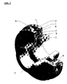
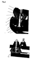
- Fig. 2 (A) Top view of the coupling according to the invention, consisting of 12 individual coupling elements (8), which in turn elastomeric bearing consisting of two rubber layers (10, 11), separated by an intermediate plate (12), and outer and inner plate (14, 13). (B) Top view of a single coupling element in the embodiment as described under (A). Fig. 3 Side view of a single coupling element (8) installed between the clutch discs (top), and individually in magnification (bottom). Fig. 4 Assembly pre-tensioning of the elements for transport and assembly preparation Fig. 5 Assembly of the elements Fig. 6 Hydraulic tension of the bolt for high preload for transmission of high frictional forces
- the coupling according to the invention can preferably be used in installations in which large torques and large forces of various kinds can occur.
- large torques and large forces of various kinds can occur.
- the invention is thus in addition to the described coupling itself and their Use for achieving optimized torsional rigidity in machines and plants, in particular wind turbines in which transmit large torques and / or forces become.
Landscapes
- Engineering & Computer Science (AREA)
- General Engineering & Computer Science (AREA)
- Mechanical Engineering (AREA)
- Mechanical Operated Clutches (AREA)
- Sliding-Contact Bearings (AREA)
- Rolling Contact Bearings (AREA)
- Mounting Of Bearings Or Others (AREA)
- Turbine Rotor Nozzle Sealing (AREA)
- Support Of The Bearing (AREA)
Priority Applications (1)
| Application Number | Priority Date | Filing Date | Title |
|---|---|---|---|
| EP05009286A EP1593867B1 (fr) | 2004-05-04 | 2005-04-28 | Accouplement avec des éléments de portage prestressés |
Applications Claiming Priority (3)
| Application Number | Priority Date | Filing Date | Title |
|---|---|---|---|
| EP04010509 | 2004-05-04 | ||
| EP04010509 | 2004-05-04 | ||
| EP05009286A EP1593867B1 (fr) | 2004-05-04 | 2005-04-28 | Accouplement avec des éléments de portage prestressés |
Publications (2)
| Publication Number | Publication Date |
|---|---|
| EP1593867A1 true EP1593867A1 (fr) | 2005-11-09 |
| EP1593867B1 EP1593867B1 (fr) | 2008-12-17 |
Family
ID=40157716
Family Applications (1)
| Application Number | Title | Priority Date | Filing Date |
|---|---|---|---|
| EP05009286A Expired - Lifetime EP1593867B1 (fr) | 2004-05-04 | 2005-04-28 | Accouplement avec des éléments de portage prestressés |
Country Status (5)
| Country | Link |
|---|---|
| EP (1) | EP1593867B1 (fr) |
| AT (1) | ATE418020T1 (fr) |
| DE (1) | DE502005006246D1 (fr) |
| DK (1) | DK1593867T3 (fr) |
| ES (1) | ES2319434T3 (fr) |
Cited By (5)
| Publication number | Priority date | Publication date | Assignee | Title |
|---|---|---|---|---|
| WO2010054808A1 (fr) * | 2008-11-17 | 2010-05-20 | Franz Mitsch | Palier asymétrique |
| WO2011063951A1 (fr) * | 2009-11-24 | 2011-06-03 | SGF SüDDEUTSCHE GELENKSCHEIBENFABRIK GMBH & CO. KG | Dispositif de transmission de couple |
| EP2508754A1 (fr) | 2011-04-04 | 2012-10-10 | Siemens Aktiengesellschaft | Système de transmission pour une éolienne |
| EP2525091A2 (fr) | 2011-05-17 | 2012-11-21 | Winergy AG | Système d'entraînement pour une éolienne |
| CN106050946A (zh) * | 2016-08-01 | 2016-10-26 | 宁波海通汽车配件股份有限公司 | 一种减振降噪法兰 |
Families Citing this family (3)
| Publication number | Priority date | Publication date | Assignee | Title |
|---|---|---|---|---|
| ES2663240T3 (es) | 2013-06-11 | 2018-04-11 | Fm Energie Gmbh & Co. Kg | Cojinete combinado para la amortiguación de vibraciones axiales y radiales |
| CN111433483B (zh) * | 2017-12-08 | 2022-06-24 | Fm能源有限责任两合公司 | 由可单独装配且可替换的弹性体轴承元件构成的轴承结构 |
| US20240110601A1 (en) | 2021-02-09 | 2024-04-04 | Fm Energie Gmbh & Co.Kg | Cardanically flexible coupling for transmitting high axial forces for drive trains in wind turbines |
Citations (3)
| Publication number | Priority date | Publication date | Assignee | Title |
|---|---|---|---|---|
| GB571470A (en) * | 1943-05-04 | 1945-08-27 | Thomas Levi Fawick | Improvements in or relating to flexible couplings |
| FR1093588A (fr) * | 1953-11-09 | 1955-05-06 | Fabrications Ind Et Automobile | Transmission mécanique avec mécanisme d'embrayage |
| US3477246A (en) * | 1968-01-10 | 1969-11-11 | William E Martin | Shaft coupling |
-
2005
- 2005-04-28 DE DE502005006246T patent/DE502005006246D1/de not_active Expired - Lifetime
- 2005-04-28 AT AT05009286T patent/ATE418020T1/de active
- 2005-04-28 EP EP05009286A patent/EP1593867B1/fr not_active Expired - Lifetime
- 2005-04-28 DK DK05009286T patent/DK1593867T3/da active
- 2005-04-28 ES ES05009286T patent/ES2319434T3/es not_active Expired - Lifetime
Patent Citations (3)
| Publication number | Priority date | Publication date | Assignee | Title |
|---|---|---|---|---|
| GB571470A (en) * | 1943-05-04 | 1945-08-27 | Thomas Levi Fawick | Improvements in or relating to flexible couplings |
| FR1093588A (fr) * | 1953-11-09 | 1955-05-06 | Fabrications Ind Et Automobile | Transmission mécanique avec mécanisme d'embrayage |
| US3477246A (en) * | 1968-01-10 | 1969-11-11 | William E Martin | Shaft coupling |
Cited By (13)
| Publication number | Priority date | Publication date | Assignee | Title |
|---|---|---|---|---|
| US8991800B2 (en) | 2008-11-17 | 2015-03-31 | Franz MITSCH | Asymmetrical mounting |
| KR101307678B1 (ko) * | 2008-11-17 | 2013-09-12 | 프란츠 미취 | 비대칭 베어링 장치 |
| CN102216637B (zh) * | 2008-11-17 | 2014-07-16 | 弗朗茨·米奇 | 不对称的支承件 |
| WO2010054808A1 (fr) * | 2008-11-17 | 2010-05-20 | Franz Mitsch | Palier asymétrique |
| WO2011063951A1 (fr) * | 2009-11-24 | 2011-06-03 | SGF SüDDEUTSCHE GELENKSCHEIBENFABRIK GMBH & CO. KG | Dispositif de transmission de couple |
| CN102725552A (zh) * | 2009-11-24 | 2012-10-10 | 弗莱康德国有限公司 | 转矩传递装置 |
| EP2508754A1 (fr) | 2011-04-04 | 2012-10-10 | Siemens Aktiengesellschaft | Système de transmission pour une éolienne |
| US8632437B2 (en) | 2011-04-04 | 2014-01-21 | Siemens Aktiengesellschaft | Drive system for a wind turbine |
| EP2525091A2 (fr) | 2011-05-17 | 2012-11-21 | Winergy AG | Système d'entraînement pour une éolienne |
| DE102011081861A1 (de) | 2011-05-17 | 2012-11-22 | Winergy Ag | Antriebssystem für eine Windkraftanlage |
| US9091327B2 (en) | 2011-05-17 | 2015-07-28 | Siemens Aktiengesellschaft | Device system for a wind turbine |
| EP2525091B1 (fr) | 2011-05-17 | 2017-06-28 | Siemens Aktiengesellschaft | Système d'entraînement pour une éolienne |
| CN106050946A (zh) * | 2016-08-01 | 2016-10-26 | 宁波海通汽车配件股份有限公司 | 一种减振降噪法兰 |
Also Published As
| Publication number | Publication date |
|---|---|
| DE502005006246D1 (de) | 2009-01-29 |
| EP1593867B1 (fr) | 2008-12-17 |
| ATE418020T1 (de) | 2009-01-15 |
| DK1593867T3 (da) | 2009-04-06 |
| ES2319434T3 (es) | 2009-05-07 |
Similar Documents
| Publication | Publication Date | Title |
|---|---|---|
| EP2352930B1 (fr) | Palier asymétrique | |
| EP2516883B1 (fr) | Douille de serrage excentrique | |
| EP2003362B1 (fr) | Elément de ressort en élastomère précontaint de manière hydraulique et son utilisation dans des supports d'éoliennes | |
| EP2895768B1 (fr) | Palier oscillant élastique | |
| DE3606318C2 (fr) | ||
| EP0462991A1 (fr) | Element de couplage elastique a la flexion et procede de fabrication correspondant. | |
| EP3012479A1 (fr) | Support a arete elastique pour eoliennes | |
| DE102014014493A1 (de) | Fadenverstärkte Gelenkvorrichtung und Kupplungsvorrichtung für einen Fahrzeugantrieb | |
| EP1046832A1 (fr) | Douille de serrage et son application dans des éoliennes | |
| EP1593867B1 (fr) | Accouplement avec des éléments de portage prestressés | |
| EP1197677B1 (fr) | Support de transmission pour éoliennes | |
| DE102011109887A1 (de) | Wellenkupplung | |
| EP2325510B1 (fr) | Embrayage doté d'un corps d'embrayage annulaire | |
| EP1564406B1 (fr) | Palier amortissant pour rotor d'éolienne | |
| DE102018005088A1 (de) | Windenergieanlage, Verfahren zum Demontieren und/oder Austauschen eines Radiallagers einer Windenergieanlage und Verfahren zur Montage einer Windenergieanlage | |
| EP2740933B1 (fr) | Eolienne | |
| EP2821665B1 (fr) | Dépôt combiné d'amortissement d'oscillations axiales et radiales | |
| DE102010006363C5 (de) | Umwuchtoptimierter Gelenkwellentilger | |
| DE102010024619B4 (de) | Vorgespanntes Differentialgetriebe ohne Zahnflankenwechsel | |
| EP1197678B1 (fr) | Amortisseur réglable pour réduire les vibrations torsionnelles | |
| EP3721113A1 (fr) | Structure de palier composée d'éléments de palier en élastomère pouvant être montés individuellement et pouvant être remplacés | |
| EP3707401A1 (fr) | Arrangement d'accouplement | |
| DE102012209767A1 (de) | Drehelastischer Dämpfer oder Kupplung mit einem Flansch zum Anschluss an einen Flansch eines weiteren Bauteils | |
| DE29806010U1 (de) | Elastomerlager | |
| EP4411164B1 (fr) | Ensembles amortisseurs pour transmissions et générateurs |
Legal Events
| Date | Code | Title | Description |
|---|---|---|---|
| PUAI | Public reference made under article 153(3) epc to a published international application that has entered the european phase |
Free format text: ORIGINAL CODE: 0009012 |
|
| AK | Designated contracting states |
Kind code of ref document: A1 Designated state(s): AT BE BG CH CY CZ DE DK EE ES FI FR GB GR HU IE IS IT LI LT LU MC NL PL PT RO SE SI SK TR |
|
| AX | Request for extension of the european patent |
Extension state: AL BA HR LV MK YU |
|
| 17P | Request for examination filed |
Effective date: 20060504 |
|
| AKX | Designation fees paid |
Designated state(s): AT BE BG CH CY CZ DE DK EE ES FI FR GB GR HU IE IS IT LI LT LU MC NL PL PT RO SE SI SK TR |
|
| 17Q | First examination report despatched |
Effective date: 20070723 |
|
| GRAP | Despatch of communication of intention to grant a patent |
Free format text: ORIGINAL CODE: EPIDOSNIGR1 |
|
| GRAS | Grant fee paid |
Free format text: ORIGINAL CODE: EPIDOSNIGR3 |
|
| GRAA | (expected) grant |
Free format text: ORIGINAL CODE: 0009210 |
|
| AK | Designated contracting states |
Kind code of ref document: B1 Designated state(s): AT BE BG CH CY CZ DE DK EE ES FI FR GB GR HU IE IS IT LI LT LU MC NL PL PT RO SE SI SK TR |
|
| REG | Reference to a national code |
Ref country code: GB Ref legal event code: FG4D Free format text: NOT ENGLISH |
|
| REG | Reference to a national code |
Ref country code: CH Ref legal event code: EP |
|
| REG | Reference to a national code |
Ref country code: IE Ref legal event code: FG4D Free format text: LANGUAGE OF EP DOCUMENT: GERMAN |
|
| REF | Corresponds to: |
Ref document number: 502005006246 Country of ref document: DE Date of ref document: 20090129 Kind code of ref document: P |
|
| REG | Reference to a national code |
Ref country code: CH Ref legal event code: NV Representative=s name: BOVARD AG PATENTANWAELTE |
|
| REG | Reference to a national code |
Ref country code: DK Ref legal event code: T3 |
|
| PG25 | Lapsed in a contracting state [announced via postgrant information from national office to epo] |
Ref country code: LT Free format text: LAPSE BECAUSE OF FAILURE TO SUBMIT A TRANSLATION OF THE DESCRIPTION OR TO PAY THE FEE WITHIN THE PRESCRIBED TIME-LIMIT Effective date: 20081217 |
|
| REG | Reference to a national code |
Ref country code: ES Ref legal event code: FG2A Ref document number: 2319434 Country of ref document: ES Kind code of ref document: T3 |
|
| PG25 | Lapsed in a contracting state [announced via postgrant information from national office to epo] |
Ref country code: FI Free format text: LAPSE BECAUSE OF FAILURE TO SUBMIT A TRANSLATION OF THE DESCRIPTION OR TO PAY THE FEE WITHIN THE PRESCRIBED TIME-LIMIT Effective date: 20081217 Ref country code: SI Free format text: LAPSE BECAUSE OF FAILURE TO SUBMIT A TRANSLATION OF THE DESCRIPTION OR TO PAY THE FEE WITHIN THE PRESCRIBED TIME-LIMIT Effective date: 20081217 Ref country code: NL Free format text: LAPSE BECAUSE OF FAILURE TO SUBMIT A TRANSLATION OF THE DESCRIPTION OR TO PAY THE FEE WITHIN THE PRESCRIBED TIME-LIMIT Effective date: 20081217 Ref country code: PL Free format text: LAPSE BECAUSE OF FAILURE TO SUBMIT A TRANSLATION OF THE DESCRIPTION OR TO PAY THE FEE WITHIN THE PRESCRIBED TIME-LIMIT Effective date: 20081217 |
|
| NLV1 | Nl: lapsed or annulled due to failure to fulfill the requirements of art. 29p and 29m of the patents act | ||
| REG | Reference to a national code |
Ref country code: IE Ref legal event code: FD4D |
|
| PG25 | Lapsed in a contracting state [announced via postgrant information from national office to epo] |
Ref country code: BG Free format text: LAPSE BECAUSE OF FAILURE TO SUBMIT A TRANSLATION OF THE DESCRIPTION OR TO PAY THE FEE WITHIN THE PRESCRIBED TIME-LIMIT Effective date: 20090317 Ref country code: RO Free format text: LAPSE BECAUSE OF FAILURE TO SUBMIT A TRANSLATION OF THE DESCRIPTION OR TO PAY THE FEE WITHIN THE PRESCRIBED TIME-LIMIT Effective date: 20081217 Ref country code: EE Free format text: LAPSE BECAUSE OF FAILURE TO SUBMIT A TRANSLATION OF THE DESCRIPTION OR TO PAY THE FEE WITHIN THE PRESCRIBED TIME-LIMIT Effective date: 20081217 Ref country code: IE Free format text: LAPSE BECAUSE OF FAILURE TO SUBMIT A TRANSLATION OF THE DESCRIPTION OR TO PAY THE FEE WITHIN THE PRESCRIBED TIME-LIMIT Effective date: 20081217 |
|
| PG25 | Lapsed in a contracting state [announced via postgrant information from national office to epo] |
Ref country code: PT Free format text: LAPSE BECAUSE OF FAILURE TO SUBMIT A TRANSLATION OF THE DESCRIPTION OR TO PAY THE FEE WITHIN THE PRESCRIBED TIME-LIMIT Effective date: 20090518 Ref country code: IS Free format text: LAPSE BECAUSE OF FAILURE TO SUBMIT A TRANSLATION OF THE DESCRIPTION OR TO PAY THE FEE WITHIN THE PRESCRIBED TIME-LIMIT Effective date: 20090417 Ref country code: SE Free format text: LAPSE BECAUSE OF FAILURE TO SUBMIT A TRANSLATION OF THE DESCRIPTION OR TO PAY THE FEE WITHIN THE PRESCRIBED TIME-LIMIT Effective date: 20090317 Ref country code: CZ Free format text: LAPSE BECAUSE OF FAILURE TO SUBMIT A TRANSLATION OF THE DESCRIPTION OR TO PAY THE FEE WITHIN THE PRESCRIBED TIME-LIMIT Effective date: 20081217 |
|
| PG25 | Lapsed in a contracting state [announced via postgrant information from national office to epo] |
Ref country code: SK Free format text: LAPSE BECAUSE OF FAILURE TO SUBMIT A TRANSLATION OF THE DESCRIPTION OR TO PAY THE FEE WITHIN THE PRESCRIBED TIME-LIMIT Effective date: 20081217 |
|
| PLBE | No opposition filed within time limit |
Free format text: ORIGINAL CODE: 0009261 |
|
| STAA | Information on the status of an ep patent application or granted ep patent |
Free format text: STATUS: NO OPPOSITION FILED WITHIN TIME LIMIT |
|
| BERE | Be: lapsed |
Owner name: MITSCH, FRANZ Effective date: 20090430 |
|
| 26N | No opposition filed |
Effective date: 20090918 |
|
| PG25 | Lapsed in a contracting state [announced via postgrant information from national office to epo] |
Ref country code: MC Free format text: LAPSE BECAUSE OF NON-PAYMENT OF DUE FEES Effective date: 20090430 |
|
| PG25 | Lapsed in a contracting state [announced via postgrant information from national office to epo] |
Ref country code: BE Free format text: LAPSE BECAUSE OF NON-PAYMENT OF DUE FEES Effective date: 20090430 |
|
| PG25 | Lapsed in a contracting state [announced via postgrant information from national office to epo] |
Ref country code: GR Free format text: LAPSE BECAUSE OF FAILURE TO SUBMIT A TRANSLATION OF THE DESCRIPTION OR TO PAY THE FEE WITHIN THE PRESCRIBED TIME-LIMIT Effective date: 20090318 |
|
| PG25 | Lapsed in a contracting state [announced via postgrant information from national office to epo] |
Ref country code: IT Free format text: LAPSE BECAUSE OF FAILURE TO SUBMIT A TRANSLATION OF THE DESCRIPTION OR TO PAY THE FEE WITHIN THE PRESCRIBED TIME-LIMIT Effective date: 20081217 |
|
| REG | Reference to a national code |
Ref country code: CH Ref legal event code: PFA Owner name: MITSCH, FRANZ Free format text: MITSCH, FRANZ#BRENTANO STRASSE 28#64646 HEPPENHEIM (DE) -TRANSFER TO- MITSCH, FRANZ#BRENTANO STRASSE 28#64646 HEPPENHEIM (DE) |
|
| PG25 | Lapsed in a contracting state [announced via postgrant information from national office to epo] |
Ref country code: LU Free format text: LAPSE BECAUSE OF NON-PAYMENT OF DUE FEES Effective date: 20090428 |
|
| PG25 | Lapsed in a contracting state [announced via postgrant information from national office to epo] |
Ref country code: HU Free format text: LAPSE BECAUSE OF FAILURE TO SUBMIT A TRANSLATION OF THE DESCRIPTION OR TO PAY THE FEE WITHIN THE PRESCRIBED TIME-LIMIT Effective date: 20090618 |
|
| PG25 | Lapsed in a contracting state [announced via postgrant information from national office to epo] |
Ref country code: TR Free format text: LAPSE BECAUSE OF FAILURE TO SUBMIT A TRANSLATION OF THE DESCRIPTION OR TO PAY THE FEE WITHIN THE PRESCRIBED TIME-LIMIT Effective date: 20081217 |
|
| PG25 | Lapsed in a contracting state [announced via postgrant information from national office to epo] |
Ref country code: CY Free format text: LAPSE BECAUSE OF FAILURE TO SUBMIT A TRANSLATION OF THE DESCRIPTION OR TO PAY THE FEE WITHIN THE PRESCRIBED TIME-LIMIT Effective date: 20081217 |
|
| PGFP | Annual fee paid to national office [announced via postgrant information from national office to epo] |
Ref country code: GB Payment date: 20140423 Year of fee payment: 10 |
|
| PGFP | Annual fee paid to national office [announced via postgrant information from national office to epo] |
Ref country code: CH Payment date: 20140411 Year of fee payment: 10 Ref country code: DE Payment date: 20140604 Year of fee payment: 10 Ref country code: ES Payment date: 20140407 Year of fee payment: 10 Ref country code: FR Payment date: 20140416 Year of fee payment: 10 Ref country code: AT Payment date: 20140408 Year of fee payment: 10 |
|
| PGFP | Annual fee paid to national office [announced via postgrant information from national office to epo] |
Ref country code: DK Payment date: 20140422 Year of fee payment: 10 |
|
| REG | Reference to a national code |
Ref country code: DE Ref legal event code: R119 Ref document number: 502005006246 Country of ref document: DE |
|
| REG | Reference to a national code |
Ref country code: DK Ref legal event code: EBP Effective date: 20150430 |
|
| REG | Reference to a national code |
Ref country code: CH Ref legal event code: PL |
|
| REG | Reference to a national code |
Ref country code: AT Ref legal event code: MM01 Ref document number: 418020 Country of ref document: AT Kind code of ref document: T Effective date: 20150428 |
|
| GBPC | Gb: european patent ceased through non-payment of renewal fee |
Effective date: 20150428 |
|
| PG25 | Lapsed in a contracting state [announced via postgrant information from national office to epo] |
Ref country code: DE Free format text: LAPSE BECAUSE OF NON-PAYMENT OF DUE FEES Effective date: 20151103 Ref country code: LI Free format text: LAPSE BECAUSE OF NON-PAYMENT OF DUE FEES Effective date: 20150430 Ref country code: CH Free format text: LAPSE BECAUSE OF NON-PAYMENT OF DUE FEES Effective date: 20150430 Ref country code: GB Free format text: LAPSE BECAUSE OF NON-PAYMENT OF DUE FEES Effective date: 20150428 |
|
| REG | Reference to a national code |
Ref country code: FR Ref legal event code: ST Effective date: 20151231 |
|
| PG25 | Lapsed in a contracting state [announced via postgrant information from national office to epo] |
Ref country code: AT Free format text: LAPSE BECAUSE OF NON-PAYMENT OF DUE FEES Effective date: 20150428 Ref country code: FR Free format text: LAPSE BECAUSE OF NON-PAYMENT OF DUE FEES Effective date: 20150430 |
|
| PG25 | Lapsed in a contracting state [announced via postgrant information from national office to epo] |
Ref country code: DK Free format text: LAPSE BECAUSE OF NON-PAYMENT OF DUE FEES Effective date: 20150430 |
|
| REG | Reference to a national code |
Ref country code: ES Ref legal event code: FD2A Effective date: 20160527 |
|
| PG25 | Lapsed in a contracting state [announced via postgrant information from national office to epo] |
Ref country code: ES Free format text: LAPSE BECAUSE OF NON-PAYMENT OF DUE FEES Effective date: 20150429 |