EP1594219A2 - Motorregler und ausser-kontrolle-detektionsverfahren - Google Patents
Motorregler und ausser-kontrolle-detektionsverfahren Download PDFInfo
- Publication number
- EP1594219A2 EP1594219A2 EP04708904A EP04708904A EP1594219A2 EP 1594219 A2 EP1594219 A2 EP 1594219A2 EP 04708904 A EP04708904 A EP 04708904A EP 04708904 A EP04708904 A EP 04708904A EP 1594219 A2 EP1594219 A2 EP 1594219A2
- Authority
- EP
- European Patent Office
- Prior art keywords
- current
- voltage
- control
- value
- motor
- Prior art date
- Legal status (The legal status is an assumption and is not a legal conclusion. Google has not performed a legal analysis and makes no representation as to the accuracy of the status listed.)
- Withdrawn
Links
Images


Classifications
-
- H—ELECTRICITY
- H02—GENERATION; CONVERSION OR DISTRIBUTION OF ELECTRIC POWER
- H02P—CONTROL OR REGULATION OF ELECTRIC MOTORS, ELECTRIC GENERATORS OR DYNAMO-ELECTRIC CONVERTERS; CONTROLLING TRANSFORMERS, REACTORS OR CHOKE COILS
- H02P21/00—Arrangements or methods for the control of electric machines by vector control, e.g. by control of field orientation
- H02P21/06—Rotor flux based control involving the use of rotor position or rotor speed sensors
- H02P21/08—Indirect field-oriented control; Rotor flux feed-forward control
Definitions
- the present invention relates to a controller for detecting a control deviant state of an AC motor in a control mode which eliminates a need of a speed sensor, such as a pulse encoder, or the like.
- an instantaneous spatial magnetic flux vector control method is applied to a controller which detects instantaneous primary voltages of U, V, and W phases through use of voltage sensors attached to at least two phases of the induction motor.
- a controller which detects instantaneous primary voltages of U, V, and W phases through use of voltage sensors attached to at least two phases of the induction motor.
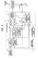
- a PG-less(i.e. speed-sensor-less) vector controller shown in Fig. 4 is hitherto available as a controller for detecting a control deviant state of an AC motor in a control mode of a slip frequency which obviates a necessity for a speed sensor such as a pulse encoder or the like.
- a voltage-type inverter 1 converts a d.c. voltage applied by a d.c. power source 16 into an a.c. voltage having an arbitrary frequency and a voltage by means of a PWM control method.
- An AC motor 2 is connected to a.c. output terminals of respective phases U, V, and W of the voltage-type inverter 1. The electric currents flowing through the respective phases of the AC motor 2 are detected by current sensors 4-1 to 4-3.
- a vector controller 3 is provided with a d-q transformer 5 which detects a primary current of the AC motor 2 and subjects the primary current to coordinate transformation, thereby sending a torque current feedback value Iq and an excitation current feedback value Id.
- the vector controller 3 is further provided with a torque current control circuit (ACRq) 7-1 and an excitation current control circuit (ACRd) 7-2.
- the torque current control circuit takes, as a torque current command value Iq*, a value output from a speed control circuit (ASR) 11 which is provided so as to cause a speed command value ⁇ r* input from a command generator 14 to coincide with an estimated speed value ⁇ r ⁇ output from a speed estimator 8 (a symbol immediately preceding a caret mark " ⁇ " depicts an "estimated value”; the same also applies to any counterparts in the following descriptions) ; and effects control such that the Iq* coincides with a torque current feedback value Iq output from the d-q transformer 5.
- the excitation current control circuit controls a voltage in the direction of an excitation current such that an excitation current command value Id* output from a magnetic flux controller 10 coincides with the excitation current feedback value Id output from the d-q transformer 5.
- a circuit which compensates for an induced voltage having developed in the AC motor 2 or a counter-electromotive voltage derived from a primary resistor r1 or a leakage inductance 1 is omitted.
- the voltage command computing unit 6 subj ects sums (Vqref, Vdref) consisting of an output from the torque current control circuit 7-1, an output from the excitation current control circuit 7-2, and values for compensating for counter-electromotive voltages to coordinate transformation through use of the phase ⁇ of an output from an integrator 12, thereby computing voltage commands (Vu*, Vv*, Vw*) of respective phases U, V, and W to thus yield a voltage command vector [v1] (the term in the brackets denotes a "vector, " and the same applies to any counterparts in the subsequent descriptions).
- the d-q transformer 5 and the voltage command computing unit 6 perform computing operations through use of Eq. 1 and Eq. 2.
- a slip frequency command computing unit 15 determines a slip frequency command value ⁇ s* from an output ⁇ * from a magnetic flux command generator 9, a torque current command value Iq*, and a set secondary resistor r2 (not shown); and adds the slip frequency command value to an estimated speed value ⁇ r ⁇ output from the speed estimator 8 through use of an adder 13 to thus compute a primary frequency command value ⁇ 1*, thereby computing a phase ⁇ by way of an integrator 12.
- the speed estimator 8 estimates and computes a magnetic flux ⁇ and the speed ⁇ r of the AC motor on the basis of the previously-described voltage command vector [v1] and the primary current vector [il].
- a control deviant sensor 17 determines whether or not a control deviant state is achieved, on the basis of behaviors of the detectedAC motor magnetic flux ⁇ , such as those provided below, through use of the AC motor magnetic flux ⁇ determined by Eq. (3) (representing an estimated value).
- This determination is based on an idea that, if vector control is established, the magnitude of the AC motor magnetic flux ⁇ coincides well with the command value ⁇ * except for a transient state; and that, if an AC motor magnetic flux failing to satisfy such a relationship is detected, a control deviant state is determined to have been achieved.
- the sensorless controller of the induction motor described in Patent Document 1 suffers the problems of: not being able to be applied to a slip-frequency-type control method which takes, as an output frequency, a primary frequency determined by adding a slip frequency to an estimated speed; not being applicable to a controller not having a voltage sensor for detecting instantaneous primary voltages of U, V, and W phases; and being incapable of detecting a control deviant state in a low-speed range.
- the second conventional motor controller suffers the problems of: not being applicable to a control method which does not determine an AC motor magnetic flux through computation or does not need to determine the same; requiring determination of a large number of predetermined values in order to make a determination about a control deviant state; and involving a longer detection time to prevent erroneous detection, which eventually becomes a factor for causing a suspension failure in the application where a motor used in a vertical direction as in the case of a crane.
- the present invention aims at providing a motor controller which can be applied to a control method ⁇ which does not require a voltage sensor and does not determine an AC motor magnetic flux ⁇ and enables detection of a control deviant state without fail in a short period of time regardless of whether the motor operates in a low-speed range or a high-speed range, as well as providing a method for detecting a control deviant state.
- a control deviant state of the AC motor in a control mode to be performed without use of a speed sensor, such as a pulse encoder can be detected as follows:
- the torque current feedback value Iq and the excitation current feedback value Id which are determined by subjecting the primary current vector [i1] of the AC motor to coordinate transformation through use of the control phase ⁇ , are to be originally detected as the amount of d.c. current, so long as the control phase ⁇ is properly controlled with respect to the AC motor phase ⁇ M.
- the torque current feedback value Iq and the excitation current feedback value Id are detected as the amount of a.c. current so as to rotate about a d-q axis, the rotational speed corresponds to the amount of time-varying change in the AC motor phase ⁇ M and the control phase ⁇ .
- occurrence of a control deviant state can be determined on the basis of whether or not the total amount has exceeded a predetermined value.
- a speed sensor such as a pulse encoder or the like
- this motor controller can detect a control deviant state of the AC motor through use of the excitation current direction voltage command value Vd* and the torque current direction voltage command value Vq* in place of Iq and Id.
- the rotational speed corresponds to the amount of time-varying change in the AC motor phase ⁇ M and the control phase ⁇ . Since the total amount of time-varying change corresponds to the amount of deviation of the control phase ⁇ from an actual phase ⁇ of the AC motor, occurrence of a control deviant state can be determined on the basis of whether or not the total amount has exceeded a predetermined value.
- control deviant method for this motor controller can detect a control deviant state of the AC motor through use of the excitation current direction voltage command value Vd* and the torque current direction voltage command value Vq* in place of Iq and Id.
- reference numeral 1 designates a voltage-type PWM inverter
- 2 designates anACmotor
- 3 designates a vector controller
- 4 designates a current sensor
- 5 designates a d-q transformer
- 6 designates a voltage command computing unit
- 7 designates a current controller
- 8 designates a speed estimator
- 9 designates a magnetic flux command generator
- 11 designates a speed controller
- 10 designates a magnetic flux controller
- 12 designates an integrator
- 13 designates an adder
- 14 designates a command generator
- 15 designates a slip frequency command computing unit
- 16 designates a d.c. power source
- 17, 17' designate control deviant sensors.
- Fig. 1 is a block diagram of a motor controller according to a first embodiment of the present invention.
- Fig. 1 is different from Fig. 3, which shows a related-art example, in that a control deviant sensor 17 is replaced by a control deviant section 17'.
- the switched control deviant sensor 17' receives, as input values, a torque current feedback value Iq and an excitation current feedback value Id from a d-q transformer 5, and determines occurrence of a control deviant state by detecting occurrence of a difference between the phase of a rotating field in the AC motor; that is, an AC motor phase ⁇ M and a control phase ⁇ output from an integrator 12.
- the amount of change per unit time (a difference between a current value and a preceding value) is integrated (step 20) .
- a control deviant state is determined to have arisen when the absolute value of the integrated value has attained a predetermined value or more (step 30).
- ⁇ i is saved (step 40). If the control state is in the base block, a preceding value pertaining to the amount of deviation and another preceding value of ⁇ i are cleared (step 50).
- the predetermined value is determined from the viewpoint of the range of values which ⁇ i can assume through normal operation and the number of times the AC motor is allowed to rotate until the motor is determined to be control deviant.
- an electrical angle is set to one to two cycles (360 degrees to 720 degrees) from the latter viewpoint, and a mechanical angle is set to about one rotation or less in the case of a four-pole motor.
- Fig. 3 is a view showing an algorithm used for detecting a control deviant state of a motor controller according to a second embodiment of the present invention.
- the second embodiment differs from the first embodiment in that in the first embodiment computation is performed on the basis of inputs of currents Iq, Id, whereas in the second embodiment computation is performed on the basis of voltage command values Vq*, Vd*.
- a control deviant sensor of the second embodiment is assigned reference numeral 17" in contrast with the control deviant sensor 17' in Fig. 1, a difference between the sensors lies solely in a computation method. For this reason, a block diagram of the second embodiment is made common to Fig. 1 and no particular illustration is provided.
- Eq. (4) and Eq. (5) which are provided below, stand on the assumption that the torque current direction voltage command value Vq* coincides with an actual value Vq of the torque current direction voltage and that the excitation current direction voltage command value Vd* coincides with an actual value Vd of the excitation current direction voltage.
- Vq * E + 3 • R 1 • Iq • + 3 • ⁇ 1 • l • Id + ACRq
- Vd * 3 • R 1 • Id - 3 • ⁇ 1 • l • Iq + ACRd
- ACRq denotes a value output from the torque current control circuit (ACRq) 7-1
- ACRd denotes a value output from the excitation current control circuit (ACRd) 7-2.
- a control deviant state can be detected even when tan -1 ( Vq */ Vd *) is used.
- tan -1 Vq */ Vd *
- the control deviant sensor 17' of the first embodiment in lieu of tan -1 ( Iq / Id )
- the control deviant sensor can be realized in totally the same manner.
- ⁇ tan -1 ( Vq */ Vd *) is calculated, thereby integrating the amount of change per unit time (step 120).
- a control deviant state is determined to have arisen (step 130).
- ⁇ v is saved (step 140).
- control state is in a base block by the first determination, the amount of deviation and the preceding value are cleared (step 150).
- Iq does not always need to be a torque current value
- Id does not always need to be an excitation current value.
- the present invention can be applied to any control method in totally the same manner, so long as the control method subj ects a detected primary current to coordinate transformation along a d-q axis to thus determine Id and Iq. The same also applies to Vd, Vq.
- controller applied to the induction motor has been described as an example of the AC motor, the present invention can be applied to a built-in magnet-type motor in totally the same manner.
- a control deviant state can be determined accurately within a short period of time by means of simple computation using the amount of control of the motor, such as an excitation current feedback value Id ⁇ which is a "d" component of an electric current ⁇ and a torque current feedback value Iq ⁇ which is a "q" component of the current ⁇ or an excitation current direction voltage command value Vd* and a torque current direction voltage command value Vq*.
Landscapes
- Engineering & Computer Science (AREA)
- Power Engineering (AREA)
- Control Of Ac Motors In General (AREA)
- Control And Safety Of Cranes (AREA)
Applications Claiming Priority (3)
| Application Number | Priority Date | Filing Date | Title |
|---|---|---|---|
| JP2003033742 | 2003-02-12 | ||
| JP2003033742A JP4797316B2 (ja) | 2003-02-12 | 2003-02-12 | 電動機制御装置および制御逸脱検出方法 |
| PCT/JP2004/001277 WO2004073152A2 (ja) | 2003-02-12 | 2004-02-06 | 電動機制御装置および制御逸脱検出方法 |
Publications (1)
| Publication Number | Publication Date |
|---|---|
| EP1594219A2 true EP1594219A2 (de) | 2005-11-09 |
Family
ID=32866244
Family Applications (1)
| Application Number | Title | Priority Date | Filing Date |
|---|---|---|---|
| EP04708904A Withdrawn EP1594219A2 (de) | 2003-02-12 | 2004-02-06 | Motorregler und ausser-kontrolle-detektionsverfahren |
Country Status (6)
| Country | Link |
|---|---|
| US (1) | US20060138992A1 (de) |
| EP (1) | EP1594219A2 (de) |
| JP (1) | JP4797316B2 (de) |
| KR (1) | KR20050104366A (de) |
| CN (1) | CN100382428C (de) |
| WO (1) | WO2004073152A2 (de) |
Families Citing this family (11)
| Publication number | Priority date | Publication date | Assignee | Title |
|---|---|---|---|---|
| JP4455248B2 (ja) * | 2004-09-24 | 2010-04-21 | 三菱電機株式会社 | 誘導電動機のベクトル制御装置 |
| JP4928850B2 (ja) | 2006-06-28 | 2012-05-09 | 株式会社東芝 | 回転機制御装置 |
| CA2659088C (en) * | 2006-07-24 | 2013-07-09 | Kabushiki Kaisha Toshiba | Variable-flux motor drive system |
| EP2192684B1 (de) * | 2007-09-18 | 2020-07-08 | Kabushiki Kaisha Toshiba | Antriebssystem mit variablem magnetfluss |
| JP4361598B1 (ja) * | 2009-03-09 | 2009-11-11 | 山洋電気株式会社 | センサレス交流電動機の制御装置 |
| US8354817B2 (en) * | 2009-06-18 | 2013-01-15 | GM Global Technology Operations LLC | Methods and systems for diagnosing stator windings in an electric motor |
| US8253365B2 (en) * | 2009-10-20 | 2012-08-28 | GM Global Technology Operations LLC | Methods and systems for performing fault diagnostics for rotors of electric motors |
| US8497698B2 (en) | 2010-08-11 | 2013-07-30 | GM Global Technology Operations LLC | Methods and systems for diagnosing faults for rotors of electric motors |
| US9018881B2 (en) | 2013-01-10 | 2015-04-28 | GM Global Technology Operations LLC | Stator winding diagnostic systems and methods |
| JP5924367B2 (ja) * | 2014-05-01 | 2016-05-25 | トヨタ自動車株式会社 | 電動車両 |
| CN105227017A (zh) * | 2015-10-27 | 2016-01-06 | 青岛远洋船员职业学院 | 一种针对船舶吊舱ssp推进器的高阶mfac的方法及系统 |
Family Cites Families (12)
| Publication number | Priority date | Publication date | Assignee | Title |
|---|---|---|---|---|
| JPH03212191A (ja) * | 1990-01-10 | 1991-09-17 | Mitsubishi Electric Corp | サイクロコンバータの制御装置 |
| JPH07236295A (ja) * | 1994-02-23 | 1995-09-05 | Yaskawa Electric Corp | 内磁形ブラシレス直流モータの駆動制御方法 |
| JP3683382B2 (ja) * | 1997-06-10 | 2005-08-17 | 三菱電機株式会社 | 誘導電動機の制御装置 |
| JPH118990A (ja) * | 1997-06-16 | 1999-01-12 | Nippon Soken Inc | 誘導モータのセンサレス制御装置 |
| JP4139934B2 (ja) * | 1999-09-21 | 2008-08-27 | 株式会社安川電機 | 交流電動機の制御方法および制御装置 |
| JP4420170B2 (ja) * | 2000-03-27 | 2010-02-24 | 三菱電機株式会社 | 同期機の回転状態検出装置および同期機の回転状態検出方法 |
| JP2001286197A (ja) * | 2000-03-31 | 2001-10-12 | Meidensha Corp | ベクトル制御装置の速度検出異常判定回路 |
| JP3719910B2 (ja) * | 2000-05-30 | 2005-11-24 | 株式会社東芝 | モータ制御装置 |
| KR100371369B1 (ko) * | 2000-08-18 | 2003-02-06 | 엘지산전 주식회사 | 유도 전동기의 벡터 제어 시스템 |
| EP1378990B1 (de) * | 2001-03-02 | 2007-12-12 | Matsushita Electric Industrial Co., Ltd. | Steuergerät für einen Elektromotor |
| JP3695342B2 (ja) * | 2001-04-11 | 2005-09-14 | 株式会社日立製作所 | 電動機の制御装置 |
| JP3668870B2 (ja) * | 2001-08-09 | 2005-07-06 | 株式会社日立製作所 | 同期電動機駆動システム |
-
2003
- 2003-02-12 JP JP2003033742A patent/JP4797316B2/ja not_active Expired - Fee Related
-
2004
- 2004-02-06 EP EP04708904A patent/EP1594219A2/de not_active Withdrawn
- 2004-02-06 CN CNB200480003999XA patent/CN100382428C/zh not_active Expired - Fee Related
- 2004-02-06 KR KR1020057014428A patent/KR20050104366A/ko not_active Ceased
- 2004-02-06 US US10/544,836 patent/US20060138992A1/en not_active Abandoned
- 2004-02-06 WO PCT/JP2004/001277 patent/WO2004073152A2/ja not_active Ceased
Non-Patent Citations (1)
| Title |
|---|
| See references of WO2004073152A2 * |
Also Published As
| Publication number | Publication date |
|---|---|
| US20060138992A1 (en) | 2006-06-29 |
| WO2004073152A2 (ja) | 2004-08-26 |
| CN1748358A (zh) | 2006-03-15 |
| WO2004073152A3 (ja) | 2004-10-07 |
| CN100382428C (zh) | 2008-04-16 |
| JP4797316B2 (ja) | 2011-10-19 |
| KR20050104366A (ko) | 2005-11-02 |
| JP2004266885A (ja) | 2004-09-24 |
Similar Documents
| Publication | Publication Date | Title |
|---|---|---|
| US6914408B2 (en) | Motor control apparatus and electric vehicle using same | |
| JP5130031B2 (ja) | 永久磁石モータの位置センサレス制御装置 | |
| TW465171B (en) | Apparatus and method for controlling a synchronous motor | |
| US6906492B2 (en) | Motor abnormality detection apparatus and electric power steering control system | |
| US6900613B2 (en) | Motor control apparatus | |
| EP1257049B1 (de) | Regelvorrichtung für eine Wechselstromquelle | |
| EP2979356B1 (de) | Motorantriebsschaltung und verfahren zur motorsteuerung | |
| JP3218954B2 (ja) | 交流モータ制御回路の異常検出装置 | |
| EP1564881A2 (de) | Regelvorrichtung für bürstenlosen Motor mit Überhitzungsschutzfunktion | |
| US11396092B2 (en) | Electric power tool provided with motor controller controlling motor including limiter for limitting current contributing to torque generation | |
| KR20020030613A (ko) | 동기 릴럭턴스 모터의 속도 제어 장치 | |
| JP4010195B2 (ja) | 永久磁石式同期モータの制御装置 | |
| EP1594219A2 (de) | Motorregler und ausser-kontrolle-detektionsverfahren | |
| US20180312196A1 (en) | Motor control apparatus and method of motor driven power steering system | |
| CN111211729B (zh) | 用于检测bldc电机过载的装置和方法 | |
| EP1557940B1 (de) | Motorregler | |
| JP3797508B2 (ja) | 永久磁石型同期電動機のセンサレス速度制御方法及びその脱調検出方法 | |
| JP4590761B2 (ja) | 永久磁石形同期電動機の制御装置 | |
| JP4402600B2 (ja) | 同期電動機の駆動システム及び同期電動機の駆動方法 | |
| KR20200059848A (ko) | Bldc 모터 과부하 감지 장치 및 방법 | |
| JP2003189673A (ja) | モータ制御装置 | |
| JP5228435B2 (ja) | インバータ制御装置とその制御方法 | |
| JP5055835B2 (ja) | 同期モータの駆動装置 | |
| JP4735287B2 (ja) | 同期モータの制御装置およびこの同期モータの制御装置を用いた制御方法 | |
| JP4143908B2 (ja) | 電動機制御装置 |
Legal Events
| Date | Code | Title | Description |
|---|---|---|---|
| PUAI | Public reference made under article 153(3) epc to a published international application that has entered the european phase |
Free format text: ORIGINAL CODE: 0009012 |
|
| 17P | Request for examination filed |
Effective date: 20050811 |
|
| AK | Designated contracting states |
Kind code of ref document: A2 Designated state(s): AT BE BG CH CY CZ DE DK EE ES FI FR GB GR HU IE IT LI LU MC NL PT RO SE SI SK TR |
|
| AX | Request for extension of the european patent |
Extension state: AL LT LV MK |
|
| DAX | Request for extension of the european patent (deleted) | ||
| RBV | Designated contracting states (corrected) |
Designated state(s): DE ES GB |
|
| STAA | Information on the status of an ep patent application or granted ep patent |
Free format text: STATUS: THE APPLICATION HAS BEEN WITHDRAWN |
|
| 18W | Application withdrawn |
Effective date: 20100125 |