EP1595681A1 - Machine de moulage a systeme de lubrification et procede de lubrification de ladite machine - Google Patents
Machine de moulage a systeme de lubrification et procede de lubrification de ladite machine Download PDFInfo
- Publication number
- EP1595681A1 EP1595681A1 EP04704729A EP04704729A EP1595681A1 EP 1595681 A1 EP1595681 A1 EP 1595681A1 EP 04704729 A EP04704729 A EP 04704729A EP 04704729 A EP04704729 A EP 04704729A EP 1595681 A1 EP1595681 A1 EP 1595681A1
- Authority
- EP
- European Patent Office
- Prior art keywords
- ball screw
- lubrication
- molding machine
- spray nozzle
- screw nut
- Prior art date
- Legal status (The legal status is an assumption and is not a legal conclusion. Google has not performed a legal analysis and makes no representation as to the accuracy of the status listed.)
- Granted
Links
- 238000005461 lubrication Methods 0.000 title claims abstract description 150
- 230000007246 mechanism Effects 0.000 title claims abstract description 103
- 238000000465 moulding Methods 0.000 title claims abstract description 25
- 238000000034 method Methods 0.000 title claims description 12
- 230000001050 lubricating effect Effects 0.000 title description 7
- 239000007921 spray Substances 0.000 claims abstract description 46
- 238000001746 injection moulding Methods 0.000 claims abstract description 11
- 239000000463 material Substances 0.000 claims description 38
- 238000002347 injection Methods 0.000 claims description 29
- 239000007924 injection Substances 0.000 claims description 29
- 238000006243 chemical reaction Methods 0.000 claims description 26
- 238000011084 recovery Methods 0.000 claims description 25
- 239000007788 liquid Substances 0.000 claims description 14
- 238000005507 spraying Methods 0.000 claims description 10
- XEEYBQQBJWHFJM-UHFFFAOYSA-N Iron Chemical compound [Fe] XEEYBQQBJWHFJM-UHFFFAOYSA-N 0.000 description 23
- 238000010438 heat treatment Methods 0.000 description 13
- 239000011347 resin Substances 0.000 description 13
- 229920005989 resin Polymers 0.000 description 13
- 238000001816 cooling Methods 0.000 description 11
- 239000004519 grease Substances 0.000 description 10
- 229910052742 iron Inorganic materials 0.000 description 10
- 239000007789 gas Substances 0.000 description 8
- 230000005540 biological transmission Effects 0.000 description 7
- 230000000694 effects Effects 0.000 description 7
- 238000010586 diagram Methods 0.000 description 6
- 239000000314 lubricant Substances 0.000 description 4
- 230000008569 process Effects 0.000 description 4
- CURLTUGMZLYLDI-UHFFFAOYSA-N Carbon dioxide Chemical compound O=C=O CURLTUGMZLYLDI-UHFFFAOYSA-N 0.000 description 3
- 238000005299 abrasion Methods 0.000 description 3
- 238000001514 detection method Methods 0.000 description 3
- 238000000889 atomisation Methods 0.000 description 2
- 229910002092 carbon dioxide Inorganic materials 0.000 description 2
- 239000001569 carbon dioxide Substances 0.000 description 2
- 239000004615 ingredient Substances 0.000 description 2
- 238000012423 maintenance Methods 0.000 description 2
- IJGRMHOSHXDMSA-UHFFFAOYSA-N Atomic nitrogen Chemical compound N#N IJGRMHOSHXDMSA-UHFFFAOYSA-N 0.000 description 1
- 238000010521 absorption reaction Methods 0.000 description 1
- 238000007599 discharging Methods 0.000 description 1
- 239000011261 inert gas Substances 0.000 description 1
- 239000002184 metal Substances 0.000 description 1
- 229910052751 metal Inorganic materials 0.000 description 1
- 239000000203 mixture Substances 0.000 description 1
- 238000012986 modification Methods 0.000 description 1
- 230000004048 modification Effects 0.000 description 1
- 231100000252 nontoxic Toxicity 0.000 description 1
- 230000003000 nontoxic effect Effects 0.000 description 1
- 239000002245 particle Substances 0.000 description 1
- 239000004014 plasticizer Substances 0.000 description 1
- 239000000843 powder Substances 0.000 description 1
- 230000001737 promoting effect Effects 0.000 description 1
- 230000003578 releasing effect Effects 0.000 description 1
- 230000000630 rising effect Effects 0.000 description 1
- 238000005096 rolling process Methods 0.000 description 1
Images


Classifications
-
- F—MECHANICAL ENGINEERING; LIGHTING; HEATING; WEAPONS; BLASTING
- F16—ENGINEERING ELEMENTS AND UNITS; GENERAL MEASURES FOR PRODUCING AND MAINTAINING EFFECTIVE FUNCTIONING OF MACHINES OR INSTALLATIONS; THERMAL INSULATION IN GENERAL
- F16H—GEARING
- F16H25/00—Gearings comprising primarily only cams, cam-followers and screw-and-nut mechanisms
- F16H25/18—Gearings comprising primarily only cams, cam-followers and screw-and-nut mechanisms for conveying or interconverting oscillating or reciprocating motions
- F16H25/20—Screw mechanisms
- F16H25/24—Elements essential to such mechanisms, e.g. screws, nuts
-
- B—PERFORMING OPERATIONS; TRANSPORTING
- B29—WORKING OF PLASTICS; WORKING OF SUBSTANCES IN A PLASTIC STATE IN GENERAL
- B29C—SHAPING OR JOINING OF PLASTICS; SHAPING OF MATERIAL IN A PLASTIC STATE, NOT OTHERWISE PROVIDED FOR; AFTER-TREATMENT OF THE SHAPED PRODUCTS, e.g. REPAIRING
- B29C45/00—Injection moulding, i.e. forcing the required volume of moulding material through a nozzle into a closed mould; Apparatus therefor
- B29C45/17—Component parts, details or accessories; Auxiliary operations
- B29C45/83—Lubricating means
-
- F—MECHANICAL ENGINEERING; LIGHTING; HEATING; WEAPONS; BLASTING
- F16—ENGINEERING ELEMENTS AND UNITS; GENERAL MEASURES FOR PRODUCING AND MAINTAINING EFFECTIVE FUNCTIONING OF MACHINES OR INSTALLATIONS; THERMAL INSULATION IN GENERAL
- F16H—GEARING
- F16H57/00—General details of gearing
- F16H57/04—Features relating to lubrication or cooling or heating
- F16H57/0456—Lubrication by injection; Injection nozzles or tubes therefor
-
- F—MECHANICAL ENGINEERING; LIGHTING; HEATING; WEAPONS; BLASTING
- F16—ENGINEERING ELEMENTS AND UNITS; GENERAL MEASURES FOR PRODUCING AND MAINTAINING EFFECTIVE FUNCTIONING OF MACHINES OR INSTALLATIONS; THERMAL INSULATION IN GENERAL
- F16H—GEARING
- F16H57/00—General details of gearing
- F16H57/04—Features relating to lubrication or cooling or heating
- F16H57/048—Type of gearings to be lubricated, cooled or heated
- F16H57/0497—Screw mechanisms
-
- B—PERFORMING OPERATIONS; TRANSPORTING
- B29—WORKING OF PLASTICS; WORKING OF SUBSTANCES IN A PLASTIC STATE IN GENERAL
- B29C—SHAPING OR JOINING OF PLASTICS; SHAPING OF MATERIAL IN A PLASTIC STATE, NOT OTHERWISE PROVIDED FOR; AFTER-TREATMENT OF THE SHAPED PRODUCTS, e.g. REPAIRING
- B29C45/00—Injection moulding, i.e. forcing the required volume of moulding material through a nozzle into a closed mould; Apparatus therefor
- B29C45/17—Component parts, details or accessories; Auxiliary operations
- B29C45/83—Lubricating means
- B29C2045/835—Lubricating means for ball screws or ball nuts
-
- B—PERFORMING OPERATIONS; TRANSPORTING
- B29—WORKING OF PLASTICS; WORKING OF SUBSTANCES IN A PLASTIC STATE IN GENERAL
- B29C—SHAPING OR JOINING OF PLASTICS; SHAPING OF MATERIAL IN A PLASTIC STATE, NOT OTHERWISE PROVIDED FOR; AFTER-TREATMENT OF THE SHAPED PRODUCTS, e.g. REPAIRING
- B29C45/00—Injection moulding, i.e. forcing the required volume of moulding material through a nozzle into a closed mould; Apparatus therefor
- B29C45/17—Component parts, details or accessories; Auxiliary operations
- B29C45/46—Means for plasticising or homogenising the moulding material or forcing it into the mould
- B29C45/47—Means for plasticising or homogenising the moulding material or forcing it into the mould using screws
- B29C45/50—Axially movable screw
- B29C45/5008—Drive means therefor
-
- F—MECHANICAL ENGINEERING; LIGHTING; HEATING; WEAPONS; BLASTING
- F16—ENGINEERING ELEMENTS AND UNITS; GENERAL MEASURES FOR PRODUCING AND MAINTAINING EFFECTIVE FUNCTIONING OF MACHINES OR INSTALLATIONS; THERMAL INSULATION IN GENERAL
- F16H—GEARING
- F16H25/00—Gearings comprising primarily only cams, cam-followers and screw-and-nut mechanisms
- F16H25/18—Gearings comprising primarily only cams, cam-followers and screw-and-nut mechanisms for conveying or interconverting oscillating or reciprocating motions
- F16H25/20—Screw mechanisms
- F16H25/22—Screw mechanisms with balls, rollers, or similar members between the co-operating parts; Elements essential to the use of such members
- F16H25/2204—Screw mechanisms with balls, rollers, or similar members between the co-operating parts; Elements essential to the use of such members with balls
- F16H25/2214—Screw mechanisms with balls, rollers, or similar members between the co-operating parts; Elements essential to the use of such members with balls with elements for guiding the circulating balls
-
- Y—GENERAL TAGGING OF NEW TECHNOLOGICAL DEVELOPMENTS; GENERAL TAGGING OF CROSS-SECTIONAL TECHNOLOGIES SPANNING OVER SEVERAL SECTIONS OF THE IPC; TECHNICAL SUBJECTS COVERED BY FORMER USPC CROSS-REFERENCE ART COLLECTIONS [XRACs] AND DIGESTS
- Y10—TECHNICAL SUBJECTS COVERED BY FORMER USPC
- Y10T—TECHNICAL SUBJECTS COVERED BY FORMER US CLASSIFICATION
- Y10T74/00—Machine element or mechanism
- Y10T74/18—Mechanical movements
- Y10T74/18568—Reciprocating or oscillating to or from alternating rotary
- Y10T74/18576—Reciprocating or oscillating to or from alternating rotary including screw and nut
- Y10T74/18744—Lubrication
Definitions
- the present invention relates to injection molding machines and, more particularly, to an electric injection molding machine having a lubrication mechanism and a lubricating method thereof.
- an injection molding machine which performs resin molding, molds a resin component by filling a resin, which has been heated and melted in a heating cylinder, into a cavity of a mold, and cooling and solidifying the resin.
- a mold for resin-molding consists of a stationary mold and a movable mold, and opening and closing of the mold is performed by moving the movable mold relative to the stationary mold by a clamping apparatus.
- an apparatus which moves the movable mold by attaching a toggle mechanism to the movable mold and driving the toggle mechanism by an electric motor
- an electric motor for moving a movable mold
- a servo motor As for such an electric motor for moving a movable mold, there is used generally a servo motor.
- a ball screw is use as a mechanism for converting a rotational movement of a rotational shaft of the servo motor.
- Such a ball screw engages with the rotational shaft of the servo motor, and it is a mechanism in which a ball screw nut engages with the ball screw via a plurality of balls.
- a ball screw nut engages with the ball screw via a plurality of balls.
- the rotational shaft of the serve motor rotates
- the ball screw nut moves relatively in an axial direction of the rotational shaft.
- the rotational shaft moves relative to the ball screw nut in the axial direction.
- a moving distance, a moving speed and a moving direction of the ball screw nut or the rotational shaft are determined by an amount of rotation, a rotating speed and a rotating direction of the rotational shaft.
- the movable mold (a movable platen) can be driven via a toggle mechanism by connecting a drive part of the toggle mechanism to the rotational shaft of the motor.
- a large load is applied in accordance with a drive force for driving the movable mold (that is, a drive force for driving the toggle mechanism).
- a lubrication material is supplied to the portions where the balls contact. That is, there are many cases in which a grease is used as a lubrication material in a ball screw drive mechanism used for a conventional injection molding machine (for example, refer to Japanese Laid-Open Patent Application No. 11-151741).
- the ball screw operates frequently during an operation of the molding machine and a large load is applied to the contact portions of the balls, a frictional heat is generated at the contact portions of the balls. Thereby, the ball screw becomes a high temperature, which is a factor of reducing the service life of the ball screw.
- a lubrication material supplied to the ball screw has an effect of promoting release of heat or an effect of cooling, the service life of the ball screw can be elongated further.
- the above-mentioned grease provides only a lubricating action by staying at the heat-generating portion, and a heat-releasing effect or a cooling effect cannot be expected.
- a more specific object of the present invention is to provide a lubrication mechanism of an electric injection molding machine that can elongate a service life of a ball screw by effectively lubricating the ball screw by directly spraying a screw part of the ball screw with a lubrication material and by a cooling effect of a gas used for the spray.
- a molding machine having a lubrication mechanism, comprising: a conversion mechanism that converts a rotational movement of a rotational shaft of a motor, which is a drive source, into a linear movement in an axial direction; and a spray nozzle that sprays an atomized lubrication material onto a component part of the conversion mechanism.
- the lubrication material of a liquid state is directly sprayed in the vicinity of a part, which needs lubrication, since the lubrication material is atomized and sprayed over the component part of the conversion mechanism. Accordingly, sufficient lubrication is achieved even if the lubrication material is in a liquid state. Additionally, heat generated by the conversion mechanism is caused to be absorbed by the lubricant material in a liquid state so as to suppress a temperature rise of the conversion mechanism.
- the spray nozzle is a nozzle that atomizes the lubrication material of a liquid state by an injection of a gas. Since the atomized lubrication material changes into a liquid state by being brought into contact with the component part, the lubricant material in the liquid state can be recovered and reused. Further, since the liquid state lubrication material, which has absorbed heat of the component part of the conversion mechanism, is recovered, the temperature rise of the conversion mechanism can be suppressed.
- the gas supplied to the spray nozzle is a compressed air, and the component part of said conversion mechanism is cooled due to adiabatic expansion when the compressed air is injected from the spray nozzle.
- the recovery means comprises a cover member surrounding the component part of the conversion mechanism, a recovery pipe, which leads the liquid state lubrication material collected in the cover member or the component part of said conversion mechanism, to a recovery container, and a pump for supplying the lubrication material collected in the recovery container to the spray nozzle. It is preferable to have cooling means for cooling the recovered lubrication material.
- said conversion mechanism is a ball screw mechanism that comprises a ball screw shaft and a ball screw nut, and said spray nozzle is attached to said ball screw nut so as to directly spray the lubrication material inside said ball screw nut.
- Said spray nozzle may be communicated with an aperture opening in an inner surface of a groove in which balls inside said ball screw nut roll, the aperture opening at a position where no load is applied by the balls.
- said spray nozzle may be communicated with an aperture opening between grooves in which balls inside said ball screw nut roll.
- the conversion mechanism may be a ball screw mechanism comprising a ball screw shaft and a ball screw nut, and the spray nozzle may be located in the vicinity of the ball screw shaft so as to directly spray the lubrication material onto the ball screw shaft.
- a molding machine having the lubrication mechanism according to the present invention may further comprise a temperature detector that detects a temperature of the ball screw nut. Additionally, it may further comprise an iron powder amount detector that measures an amount of iron powder contained in the recovered lubrication material.
- the molding machine having the lubrication mechanism according to the present invention may be an electric injection molding machine.
- a lubrication method of a molding machine comprising spraying an atomized lubrication material to a component part of a conversion mechanism that converts a rotational movement of a rotational shaft of a motor, which is a drive source of a clamping apparatus, into a linear movement in an axial direction.
- the gas may be a compressed air
- the component part of the conversion mechanism may be cooled due to adiabatic expansion when the compressed air is injected.
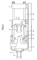
- FIG. 1 is an outline structure diagram of the example of the clamping apparatus in which the lubrication mechanism according to the present invention is incorporated.
- the clamping apparatus shown in FIG. 1 comprises a stationary platen 11 fixed to a frame 10 and a movable platen 12 movable relative to the stationary platen.
- a toggle support 13 as a base support is movably provided relative to the frame 10 with a predetermined distance to the stationary platen 11.
- Tie bars 14 are provided between the fixed platen 11 and the toggle support 13.
- the movable platen 12 is arranged in a state where it faces the stationary platen 11, and is movable along the tie bars 14.
- a stationary mold (not shown in the figure) is attached to a surface of the stationary platen 11 facing the movable platen 12, and a movable mold (not shown in the figure) is attached to a surface of the movable platen facing the stationary platen 11.
- a drive apparatus for an ejector is attached to a rear side of the movable platen 12.
- the drive apparatus for the ejector has a motor 15 as a drive source so as to move an ejector rod 16 forward or rearward.
- ejector pins (not shown in the figure) are driven so as to push a molded component out of the cavity of the movable mold.
- a toggle mechanism 17 is provided between the movable platen 12 and the toggle support 13. Additionally, a drive apparatus 18 as drive means for clamping is provided on a rear end (a left end in FIG. 1) of the toggle support 13. The drive apparatus 18 comprises a motor 19 so as to cause the toggle mechanism to operate by moving a cross head 20 as a member to be driven forward or rearward.
- the movable platen 12 is moved toward the stationary platen 11 so as to perform mold closing, and a clamping force, which is a thrust force by the motor 19 multiplied by a torque magnifying power, is exerted on the movable platen 12.
- a clamping force which is a thrust force by the motor 19 multiplied by a torque magnifying power
- the movable mold attached to the movable platen 12 is pressed against the stationary mold attached to the stationary platen 11 so as to perform mold clamping.
- a thrust force generated by the motor 19 may be applied directly to the movable platen 12 without using the toggle mechanism 17.
- the motor 19 is preferably an electric servo motor that can control a rotational speed or a rotational direction.
- the above-mentioned toggle mechanism 17 comprises a toggle lever 21 movably supported with respect to the cross head, a toggle lever 22 swingably supported with respect to the toggle support 13, and a toggle arm 23 swingably supported with respect to the movable platen 12. Between the toggle lever 21 and the toggle lever 22 and between the toggle lever 22 and the toggle arm 23 are connected by link connections.
- the above-mentioned clamping apparatus uses the motor 19 as a drive source of the link mechanism 17, which drives the movable platen 12, and, a ball screw mechanism is incorporated into the motor 19. That is, it is constituted so that one of the ball screw shaft and the ball screw nut of the ball screw mechanism moves in an axial direction when the rotational shaft of the motor 19 rotates, and the toggle mechanism will is also operated in connection with it.
- FIG. 7 is a cross-sectional view of an injection apparatus 100 of a built-in motor as an example of an injection apparatus.
- an injector nozzle 112a is provided at a front end of a heating cylinder 112 as a cylinder member.
- a screw 122 is provided inside the heating cylinder 112 so as to be movable forward and rearward (left and right directions in FIG. 7) and rotatable.
- the screw 122 has a screw head 122a on a front end thereof, and extends rearward inside the heating cylinder 112, and is fixed to a bearing box 113 at a rear end. Additionally, a spiral flight 123 is formed around the screw 122, and a groove 126 is formed between the grooves 126.
- a hopper (not shown in the figure) is connected to a resin supply port formed in a predetermined portion of the heating cylinder 112.
- the resin supply port is formed in the portion at a rear end portion of the groove 126 in a state where the screw 122 is at the forefront position (left side in FIG. 7) in the heating cylinder 112.
- pellet-like resin is supplied to the heating cylinder 122 from inside the hopper and the resin is moved in a direction toward the screw head 122a in the groove 126.
- a heater (not shown in the figure) is provided as heating means around the heating cylinder 122 so that the resin in the groove 126 is melted by heating the heating cylinder 112 by the heater and rotating the screw 122. Accordingly, if the screw is moved rearward by a predetermined distance while rotating, a melted resin corresponding to one shot can be stored in front of the screw head 122a.
- the resin stored in front of the screw head 122a is injected from the injection nozzle 112a, and is filled into the cavity of the mold apparatus.
- a drive part 115 for reciprocating and rotating the screw 122 is provided.
- the drive part 115 is equipped with a frame 117, a metering motor 181 movably provided to the frame 117 and an injection motor fixed to the frame 117.
- a motor 182 for injection and the screw 122 are arranged on the same axis.
- a guidance bar 183 which extends in parallel with the screw 122, is provided on the frame 117, and the metering motor 181 is moved along the guidance bar 183.
- a support board 184 is slidably provided with respect to the guidance bar 183, and the metering motor 181 is attached to the support board 184.
- a drive-side pulley 186 is fixed to an output shaft 185 of the metering motor 181, and an driven-side pulley 188 is fixed to an outer circumference of a box body 187 of the bearing box 133.
- a timing belt 189 is provided over the drive-side pulley 186 and the driven-side pulley 188. It should be noted that transmission means connecting the bearing box 113 with the metering motor 181 is constituted by the by the drive-side pulley 186, the driven-side pulley 186 and the timing belt 189.
- the motor 182 for injection comprises a stator fixed to the frame 117 and a rotor 192 provided an inner circumference side of the stator 191, and the rotor 192 is rotatably supported with respect to the frame 117. Accordingly, a hollow rotor shaft 193 is fitted and fixed to the rotor 192, and both ends of the rotor shaft 193 are supported on the frame by bearings 194 and 195.
- bearings 196 and 197 are provided in the bearing box 113, and the screw 122 and a ball screw shaft/spline shaft unit 198 are coupled in a relatively rotatable manner by the bearings 196 and 197.
- a ball nut 199 fixed to the frame 117 via a load meter 205 as load detecting means is engaged with a ball screw shaft part 198a as a movement direction conversion part formed on a front part of the ball screw shaft/spline shaft unit 198.
- drive transmission means for restricting a relative movement in an axial direction and permitting a relative movement in a rotating direction is constituted between the screw 122 and the ball screw shaft/spline shaft unit 198 by the bearing box 113.
- means for converting a rotational movement into a linear movement is constituted by the ball nut 199 and the ball screw shaft part 198a.
- the rotation of the metering pump is transmitted sequentially to the drive-side pulley 186, the timing belt 189, the box body 187 and the screw 122, and the screw 122 is rotated.
- the screw 122 and the ball screw shaft/spline shaft unit 198 are coupled relatively rotatably via the bearing box 113, the rotation transmitted to the box body 187 is not transmitted to the ball screw shaft/spline shaft unit 198.
- a pressure of the resin in the heating cylinder 112 is transmitted to the ball screw shaft/spline shaft unit 198 via the bearing box 113.
- the ball screw shaft/spline shaft unit 198 moves rearward while rotating, and, in connection with this, the screw is caused to rotate and move rearward. It should be noted that a back pressure is applied to the screw 122 against the pressure of the resin when the screw 122 is moved rearward.
- the screw 122 can be gradually advanced without rotating the screw 122 by supplying an electric current of a predetermined frequency to the stator 191 in the motor 182 for injection.
- an annular engaging member 201 is fixed to a substantially middle of an inner side of the rotor shaft 193.
- a spline 202 formed on an inner circumference of an engagement member 201 is brought into engagement with a spline shaft part 198a as a rotation transmission part formed on an outer circumference of a rear part of the ball screw shaft/spline shaft unit 198.
- rotation transmission means by which a rotation of the motor 82 for injection motor 82 is transmitted is constituted by the spline 102 and the spline shaft part 198b.
- the metering motor 181 and the screw shaft/spline shaft unit 198 are arranged on different axes in the above-mentioned example, the motor for injection, the ball screw shaft/spline unit and the screw may be arranged on different axes from each other.
- FIG. 2 is a cross-sectional view of the ball screw mechanism incorporated in the motor 19 shown in FIG. 1.
- the ball screw mechanism shown in FIG. 2 comprises a ball screw nut 25 and a ball screw shaft 26.
- the ball screw nut 25 and the ball screw shaft 26 are provided with spiral grooves having the same pitch, and a plurality of balls 27 as power transfer members are arranged between the groove of the ball screw nut 25 and the groove of the ball screw shaft 26.
- a return tube 25a is attached to the ball screw nut 25 by a return tube attachment member 25b. Thereby, the balls 27 circulates while rolling between the spiral groove of the ball screw shaft 26 and the spiral groove of the ball screw nut 25 and inside the return tube 25a.
- the power transmission members of the above-mentioned ball screw mechanism are the plurality of balls
- a plurality of rollers having about the same size as the balls may be used as the power transmission members.
- a planetary roller may be used as the power transmission members. It should be noted that the rotational/linear movement converting mechanism using a plurality of rollers or the rotational/linear movement converting mechanism using a planetary roller is well-known, and a detailed description thereof will be omitted.
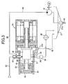
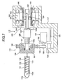
- FIG. 3 is a structure diagram showing an entire drive apparatus provided with the lubrication mechanism according to the first embodiment of the present invention.
- the drive apparatus 30 shown in FIG. 3 is a part corresponding to the drive apparatus 18 shown in FIG. 1, and serves as a drive source for driving the toggle mechanism of the clamping apparatus. It should be noted that the drive apparatus 30 in FIG. 3 is shown in an orientation of which left and right are reversed with respect to the drive apparatus shown in FIG. 1, and in the same orientation as the drive part 115 of the injection apparatus shown in FIG. 7.
- the drive apparatus 30 comprises a motor 19 as a power source and a ball screw mechanism 31 driven by the motor 19.
- the motor 19 is an electric servo motor of which rotating direction and rotating speed are controllable.
- the ball screw mechanism 31 has the ball screw nut 25 and the ball screw shaft 26 as shown in the FIG. 2.
- the ball screw nut 25 is fixed to a housing of the motor 19.
- the ball screw shaft 26 is movable in a direction of the rotational axis while rotating integrally with the rotational shaft (rotor) of the motor 19.
- a moving member 32 is attached to an end of the ball screw shaft 26 via a baring.
- the moving member 32 is connected to the cross head 20 of the toggle mechanism 17 so that the toggle mechanism 17 operates with a reciprocating movement of the moving member. Additionally, when the drive apparatus 30 is provided to the injection apparatus, the moving member 32 corresponds to the box body 187 of the bearing box 113.
- a generally cylindrical cover member 33 is provided so as to cover the ball screw mechanism 31 and the moving member 32.
- the moving member 32 is constituted to be movable in the cover member 33, and a seal member 34 is provided between the moving members 32 and the cover member 33 so as to form a sealed space 45.
- a spray nozzle 35 for spraying lubrication oil which is the lubrication material for lubricating the ball screw mechanism 31, is attached to the cover member 33.
- an end portion of the spray nozzle 35 extends to inside the ball screw nut 25 so as to directly spray the atomized lubrication oil inside the ball screw nut 25 as mentioned later.
- the lubrication oil and compressed air are supplied to the spray nozzle 35 so as to atomize the lubrication oil into appropriate particles by powerfully injecting the compressed air from a nozzle tip.
- the atomized lubrication oil adhere onto the ball groove of the ball screw shaft 26 and the ball groove of the ball screw nut 25 an surfaces of the balls 27, which are component parts of the ball screw mechanism so as to form lubrication oil films at contact portions between each of the ball groove of the ball screw shaft 26 and the ball groove of the ball screw nut 25 and each of the balls 27.
- the compressed air injected inside the ball screw nut 25 adiabatically expands, thereby absorbs heat in surrounding area. That is, the balls 27, the ball screw nut 25 and the ball screw shaft 26 of which temperatures are raised due to friction heat generated by a movement of the balls inside the ball screw nut 25 are cooled by the adiabatically expanded injection air.
- the lubrication oil turned into a liquid state by adhering onto the balls 27, the ball screw nut 25 and the ball screw shaft 26 is discharged from the inside of the ball screw nut 25.
- the lubrication oil also absorbs heat from the surrounding area and discharged from the inside of the ball screw nut 25, there also is a cooling effect by the lubricant oil itself.
- the gaseous matter (gas) for atomization is not limited to the compressed air.
- an inert gas such as nitrogen (N 2 ) or a nontoxic compressible gas such as carbon dioxide (CO 2 ) may be used as the gas for atomization.
- An aperture (opening) for recovering the lubrication oil is provided in a lower-side portion of the ball screw nut 25 and a lubrication oil recovery pipe 36 is connected thereto.
- the lubrication oil recovery pipe 36 extends through the cover member 33, and is connected to the lubrication oil recovery tank 37. Accordingly, the lubrication oil turned into a liquid state in the ball screw nut 25 flows into the lubrication oil recovery pipe 35, and is guided to the lubrication oil recovery tank 37.
- An iron amount detector 39 and a cooler 40 are provided in the middle of the lubrication oil recovery pipe 36.
- the iron amount detector 39 detects an amount of iron component contained in the lubrication oil.
- the iron component contained in the lubrication oil is caused by abrasion of component parts of the ball screw mechanism 31, and, thus, an amount of abrasion of the ball screw mechanism 31 can be estimated by detecting the amount of iron component. Accordingly, an operator or a maintenance can estimate a service life of the ball screw mechanism by causing the detection result of the iron amount detector 39 to be displayed on a display unit. Additionally, the detection result of the iron amount detector 39 may be supplies to a controller to calculate a service life and display or an operator is notified of a fact that a service life of the ball screw mechanism is ended when an amount of iron component exceeds a predetermined value.
- the cooler 40 is for cooling the recovered lubrication oil.
- the lubrication oil collected from the ball screw nut 25 has a high temperature due to absorption of heat from the ball screw nut 25 and the ball screw shaft 26, and it is for reuse by cooling it.
- a part of the lubrication oil in the ball screw nut leaks out from an end of the ball screw nut 25, and stored in the cover member 33.
- An aperture (opening) 33a for discharging the lubrication oil is provided in a lower portion of the cover member 33, and a lubrication oil recovery pipe 38 is connected thereto.
- the lubrication oil recovery pipe 38 is connected to the lubrication oil recovery tank 37, and, thus, the lubrication oil stored in the bottom portion of the cover member 33 flows through the lubrication oil recovery pipe 38 and is guided to the lubrication oil recovery tank 37.
- the lubrication oil recovery tank 37 is provided with a recessed portion 37a on the bottom of the center so as to be configured so that impure ingredient such as metal powder (iron powder) or the like contained in the flowing lubricant oil is stored therein.
- the impure ingredient stored in the recessed portion 37a is discharged by opening a drain valve periodically or when accumulated in some amount.
- the lubrication oil recovered and stored in the lubrication oil recovery tank 37 is suctioned by a lubrication oil pump 41, and is supplied to the spray nozzle 35 through a lubrication oil supply pipe 42.
- the lubrication oil supplied to the spray nozzle 35 is atomized by injection of the compressed air supplied through a compressed air supply pipe 43, and sprayed inside the ball screw nut 25 again.
- the cost spent on lubrication can be reduced.
- a service life can be estimated by detection of iron using the recovered lubrication oil as mentioned above, and the recovered lubrication oil can be reused by cooling it.
- the cover 33 forms the sealed space 45, heat generated by the ball screw does not leak to a surrounding area of the drive apparatus, and, therefore, a temperature of the surrounding area of the drive apparatus can be prevented from rising.
- the cooling effect can be checked by detecting a temperature of the ball screw nut 25 by providing a temperature sensor 44 to the ball screw nut 25, and the ball screw mechanism 31 can be efficiently cooled by adjusting an amount of supply and a temperature of the lubrication oil.
- iron amount detector 39 and the cooler 40 are provided in the middle of the lubrication oil recovery pipe 36 in the example shown in FIG. 3, they may be provided to the lubrication oil recovery tank 37 or in the middle of the lubrication oil supply pipe 42.
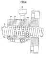
- FIG. 4 is a cross-sectional view showing an example of spraying the lubrication oil onto the balls 27 in the ball screw nut 25
- FIG. 5 is a cross-sectional view showing an example of spraying the lubrication oil onto the ball screw shaft 26 in the ball screw nut 25.
- the lubrication oil is sprayed at a position as close as possible to a portion that requires lubrication so as to achieve efficient lubrication.
- the lubrication oil supply aperture 25a is provided to the ball screw nut 25, and the tip part of the spray nozzle 35 is attached thereto.
- the lubrication oil supply aperture 25a is opens at almost center of the ball screw groove formed in the ball screw groove so that the lubrication oil atomized by the spray nozzle 35 is directly sprayed onto the balls 27.
- the ball screw incorporated into the injection molding machine receives a load mainly only in one direction, the load is applied to only one side of the ball screw groove.
- the opening may be provided at a position of the ball screw groove offset in a direction where no load is received.
- the balls 27 are brought into contact with a side surface portion in the inner surface of the ball screw groove of the ball screw nut 25. That is, a load is hardly applied to a center portion of the ball screw groove.
- the opening of the lubrication oil supply aperture 25a is provided in the portion where no load is applied, and, thereby, the lubrication oil is directly sprayed onto the balls 27 while acquiring the portion of the ball screw groove in contact with the balls.
- a lubrication oil recovery aperture 25b is provided to a lower portion of the opposite side of the lubrication oil supply aperture 25a, and the lubrication oil recovery pipe 36 is connected thereto.
- the atomized lubrication oil sprayed from the spray nozzle 35 hits the balls 27 by passing through the lubrication oil supply aperture 25a and adheres onto the surfaces of the balls 27 so as to form lubrication oil films.
- the lubrication oil lubricating the balls 27 is stored in a lower part of the inside of the ball screw nut 25, and is discharged outside the ball screw nut 25 through the lubrication oil recovery aperture 25b and the lubrication oil recovery pipe 36.
- the lubrication oil supply aperture 25a opens between each of the ball screw grooves spirally formed in the ball screw nut 25, and the lubrication oil atomized by the spray nozzle 35 is directly sprayed onto the surface of the ball screw shaft 26. That is, a part requiring the lubrication oil is a part of the ball screw groove, and the lubrication oil is supplied to the part so that an efficient supply of the lubrication oil is achieved.
- spray nozzle 35 is provided in the examples shown in FIG. 4 and FIG. 5, a plurality of spray nozzles may be provided so as to spray the lubrication oil at a plurality of positions.
- seal materials are provided on both ends of the ball screw nut 25 so as to store the lubrication oil in the ball screw nut 25.
- seal materials are not provided in the present invention so as to configure so that the lubrication oil and the compressed air can be easily discharged from both ends of the ball screw nut 25. Accordingly, the compressed air injected from the spry nozzle 35 is rapidly discharged from the ball screw nut 25. Thereby, the spray of the lubrication oil can be performed efficiently in the ball screw nut 25, which causes the atomized lubrication oil being efficiently diffused to an entire interior of the ball screw nut 25.
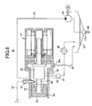
- FIG. 6 is a structure diagram of the entire drive apparatus provided with the lubrication mechanism according to the second embodiment of the present invention.
- parts that are the same as the parts shown in FIG. 3 are given the same reference numerals, and descriptions thereof will be omitted.
- the lubrication mechanism shown in FIG. 2 has the same composition parts as the lubrication mechanism shown in FIG. 6, the positions of attaching the spray nozzle 35 differ. That is, in the lubrication mechanism shown in FIG. 6, the spray nozzle 35 does not spray the lubrication oil inside the ball screw nut 25 but sprays the atomized lubrication oil onto the surface of the ball screw shaft extending from the ball screw nut 25. Since the ball screw shaft 26 always reciprocates in the axial direction during operation of the ball screw mechanism 31, the lubrication oil adhering onto the surface of the ball screw shaft 26 is supplied to inside the ball screw nut 25 in association with the movement of the ball screw shaft 26.
- lubrication oil is used as a lubrication material in the above-mentioned first and second embodiments, any lubrication materials may be used if they are in a liquid state and can be atomized by the spray nozzle 35.
- the ball screw mechanism is explained as an example in the above-mentioned first and second embodiments, it can be applies to a rotational/linear movement conversion mechanism according to a roller screw mechanism or a planetary gear.
- the present invention is applied to the clamping drive part and the injection drive part is mainly explained in the present embodiments.
- the present invention can be more effectively applied in a case it is applied to an injection apparatus in which a maximum load is generated over a whole injection stroke than in a case where it is used for a ball screw in which a section where a maximum load is generated is a part of a hole opening and closing stroke. Additionally, the same effect is obtainable when applying the present invention to an ejector apparatus, a plasticizer moving apparatus or the like.
Landscapes
- Engineering & Computer Science (AREA)
- General Engineering & Computer Science (AREA)
- Mechanical Engineering (AREA)
- Manufacturing & Machinery (AREA)
- Transmission Devices (AREA)
- Injection Moulding Of Plastics Or The Like (AREA)
- Moulds For Moulding Plastics Or The Like (AREA)
Applications Claiming Priority (3)
| Application Number | Priority Date | Filing Date | Title |
|---|---|---|---|
| JP2003017556 | 2003-01-27 | ||
| JP2003017556 | 2003-01-27 | ||
| PCT/JP2004/000578 WO2004067258A1 (fr) | 2003-01-27 | 2004-01-23 | Machine de moulage a systeme de lubrification et procede de lubrification de ladite machine |
Publications (3)
| Publication Number | Publication Date |
|---|---|
| EP1595681A1 true EP1595681A1 (fr) | 2005-11-16 |
| EP1595681A4 EP1595681A4 (fr) | 2006-06-28 |
| EP1595681B1 EP1595681B1 (fr) | 2011-04-13 |
Family
ID=32820566
Family Applications (1)
| Application Number | Title | Priority Date | Filing Date |
|---|---|---|---|
| EP04704729A Expired - Lifetime EP1595681B1 (fr) | 2003-01-27 | 2004-01-23 | Machine de moulage a systeme de lubrification et procede de lubrification de ladite machine |
Country Status (9)
| Country | Link |
|---|---|
| US (1) | US20050255186A1 (fr) |
| EP (1) | EP1595681B1 (fr) |
| JP (1) | JPWO2004067258A1 (fr) |
| KR (1) | KR100666449B1 (fr) |
| CN (1) | CN1744980A (fr) |
| AT (1) | ATE505314T1 (fr) |
| DE (1) | DE602004032215D1 (fr) |
| TW (1) | TWI230653B (fr) |
| WO (1) | WO2004067258A1 (fr) |
Cited By (7)
| Publication number | Priority date | Publication date | Assignee | Title |
|---|---|---|---|---|
| CN103379988A (zh) * | 2011-02-15 | 2013-10-30 | 克劳斯玛菲科技有限公司 | 合模装置 |
| EP2851581A4 (fr) * | 2012-11-13 | 2016-06-22 | Si Chuan Zhong Shun Solar Energy Dev Co Ltd | Appareil d'entraînement linéaire et son procédé de commande et d'utilisation pour suivi d'énergie solaire |
| WO2017048788A1 (fr) * | 2015-09-14 | 2017-03-23 | Tolomatic, Inc. | Diagnostic et pronostic d'actionneur |
| US10458529B2 (en) | 2015-01-23 | 2019-10-29 | Mitsubishi Heavy Industries Compressor Corporation | Linear motion mechanism, valve device, and steam turbine |
| DE102018209703A1 (de) | 2018-06-15 | 2019-12-19 | Skf Motion Technologies Ab | Baueinheit für einen Linearaktuator |
| DE102018209700A1 (de) | 2018-06-15 | 2019-12-19 | Skf Motion Technologies Ab | Baueinheit |
| EP2705940B1 (fr) * | 2012-09-11 | 2020-06-10 | Sumitomo Heavy Industries, Ltd. | Machine de moulage à injection |
Families Citing this family (46)
| Publication number | Priority date | Publication date | Assignee | Title |
|---|---|---|---|---|
| US20050242003A1 (en) * | 2004-04-29 | 2005-11-03 | Eric Scott | Automatic vibratory separator |
| US8312995B2 (en) | 2002-11-06 | 2012-11-20 | National Oilwell Varco, L.P. | Magnetic vibratory screen clamping |
| TWI248078B (en) * | 2004-03-03 | 2006-01-21 | Asustek Comp Inc | Automatic oiling device for screw of optical disc player |
| JP2007292221A (ja) * | 2006-04-26 | 2007-11-08 | Fujitsu Ltd | 構造体および記録媒体駆動装置並びに潤滑膜付きねじ |
| US20080083566A1 (en) | 2006-10-04 | 2008-04-10 | George Alexander Burnett | Reclamation of components of wellbore cuttings material |
| JP4670796B2 (ja) * | 2006-11-21 | 2011-04-13 | パナソニック株式会社 | 軸上移動機構及び電子部品実装装置 |
| JP4842873B2 (ja) * | 2007-03-29 | 2011-12-21 | 住友重機械工業株式会社 | 型締装置 |
| JP5419392B2 (ja) * | 2007-08-24 | 2014-02-19 | Ntn株式会社 | 転がり軸受装置 |
| US8622220B2 (en) | 2007-08-31 | 2014-01-07 | Varco I/P | Vibratory separators and screens |
| JP5079429B2 (ja) * | 2007-09-04 | 2012-11-21 | 東洋機械金属株式会社 | 成形機 |
| DE112008003892T5 (de) * | 2008-05-26 | 2011-06-09 | Sumitomo Heavy Industries, Ltd. | Formklemmvorrichtung |
| DE102008028335B3 (de) * | 2008-06-13 | 2010-05-06 | Limoss Gmbh & Co. Kg | Linearer Stellantieb für Sitz- und/oder Liegemöbel |
| US9073104B2 (en) | 2008-08-14 | 2015-07-07 | National Oilwell Varco, L.P. | Drill cuttings treatment systems |
| DE102008051285B3 (de) * | 2008-10-10 | 2010-07-22 | Karl Hehl | Formschließeinheit für Spritzgießformen |
| US9079222B2 (en) | 2008-10-10 | 2015-07-14 | National Oilwell Varco, L.P. | Shale shaker |
| US8556083B2 (en) | 2008-10-10 | 2013-10-15 | National Oilwell Varco L.P. | Shale shakers with selective series/parallel flow path conversion |
| JP2010253997A (ja) * | 2009-04-21 | 2010-11-11 | Sumitomo Metal Ind Ltd | 鉄道車両用振動制御装置 |
| DE102010045069A1 (de) * | 2010-09-10 | 2012-03-15 | Robert Bosch Gmbh | Linearbewegungsvorrichtung mit automatisierbarer Schmiermittelzuführung |
| JP5628102B2 (ja) * | 2011-06-29 | 2014-11-19 | 住友重機械工業株式会社 | 射出装置 |
| EP2650562A1 (fr) | 2012-04-10 | 2013-10-16 | Aktiebolaget SKF | Ensemble vis et écrou avec capteur de température |
| JP5917425B2 (ja) * | 2013-02-13 | 2016-05-11 | 住友重機械工業株式会社 | 射出成形機 |
| CN103978650B (zh) * | 2013-02-13 | 2017-07-18 | 住友重机械工业株式会社 | 注射成型机 |
| US9643111B2 (en) | 2013-03-08 | 2017-05-09 | National Oilwell Varco, L.P. | Vector maximizing screen |
| TWI513926B (zh) * | 2013-07-16 | 2015-12-21 | Nat Univ Chung Cheng | Ball screw for immediate monitoring of torque |
| JP5877890B2 (ja) * | 2014-07-18 | 2016-03-08 | Thk株式会社 | ねじ装置用冷却ノズル及び運動案内装置用冷却ノズル |
| US9587732B2 (en) * | 2015-01-27 | 2017-03-07 | Honeywell International Inc. | Translating nut mechanisms having enhanced lubrication features and variable bleed valve systems employing the same |
| CN105736661B (zh) * | 2016-04-27 | 2018-12-11 | 扬州诚德重工有限公司 | 一种丝杆传动双球面滑动旋转装置 |
| DE102016119581A1 (de) * | 2016-10-13 | 2018-04-19 | Arburg Gmbh + Co. Kg | Formschließeinheit mit Wärmemanagement |
| DE102017214812A1 (de) * | 2017-08-24 | 2019-02-28 | Robert Bosch Gmbh | Gewindetrieb |
| CN107457288A (zh) * | 2017-10-17 | 2017-12-12 | 董杰 | 一种基于工业机械的折弯机挡料装置 |
| JP7077103B2 (ja) * | 2018-03-28 | 2022-05-30 | 住友重機械工業株式会社 | 射出成形機 |
| CN108468770A (zh) * | 2018-05-30 | 2018-08-31 | 平湖市祥瑞机械设备制造有限公司 | 一种用于数控设备中丝杆传动机构 |
| CN110271849B (zh) * | 2019-04-15 | 2024-09-06 | 上海荟阁机械科技有限公司 | 一种螺旋式升降机 |
| US11105403B2 (en) * | 2019-09-05 | 2021-08-31 | Hiwin Technologies Corp. | Ball screw |
| JP7557167B2 (ja) * | 2020-03-24 | 2024-09-27 | セイコーエプソン株式会社 | 射出成形装置及び三次元造形装置 |
| US12460714B2 (en) * | 2020-08-24 | 2025-11-04 | Nsk Ltd. | Method and device for sealing grease into ball screw device, ball screw device, method for producing ball screw device, method for producing linear actuator, method for producing vehicle brake, and method for producing vehicle |
| CN112096840B (zh) * | 2020-09-15 | 2022-08-12 | 马鞍山福永智能科技有限公司 | 一种高精度光热发电用回转式减速器 |
| CN114101424B (zh) * | 2021-11-26 | 2024-01-16 | 临沂市金立机械有限公司 | 一种背负式机架双向自动成型装置 |
| CN114227343B (zh) * | 2021-12-29 | 2022-11-08 | 东莞市宝科精密机械有限公司 | 一种x轴丝杆机构 |
| CN114310414A (zh) * | 2021-12-30 | 2022-04-12 | 江苏亚如捷车业有限公司 | 一种用于汽车机盖加工的夹具定位机构 |
| CN115446402B (zh) * | 2022-08-03 | 2025-03-04 | 烟台艾迪精密机械股份有限公司 | 一种对滚珠丝杠的丝杆滚道面进行电火花毛化处理的方法 |
| US12535123B2 (en) | 2023-02-08 | 2026-01-27 | Archibald Corporation | Electric motor having stationary drive mechanism |
| CN116510369A (zh) * | 2023-04-12 | 2023-08-01 | 盐城市星火阀业制造股份有限公司 | 一种压滤机用卸料装置 |
| CN117189810A (zh) * | 2023-09-14 | 2023-12-08 | 同济大学 | 一种阻尼力高的旋转式电涡流阻尼器及其使用方法 |
| CN117239998B (zh) * | 2023-11-14 | 2024-01-23 | 常州鑫鼎机电设备有限公司 | 一体式电推杆 |
| CN117404457B (zh) * | 2023-12-15 | 2024-02-20 | 常州瑞倍特自动化设备有限公司 | 智能型电动执行器 |
Family Cites Families (13)
| Publication number | Priority date | Publication date | Assignee | Title |
|---|---|---|---|---|
| DE19519770C2 (de) * | 1994-05-30 | 2002-10-24 | Nsk Ltd | Kugelumlaufspindel |
| JP2866019B2 (ja) * | 1995-01-27 | 1999-03-08 | 住友重機械工業株式会社 | 電動射出成形機の射出装置 |
| US5809838A (en) * | 1995-05-30 | 1998-09-22 | Nsk Ltd. | Ball screw device with means for maintaining balance |
| JPH102396A (ja) * | 1996-06-14 | 1998-01-06 | Mitsubishi Heavy Ind Ltd | ボールねじの洗浄装置 |
| JP2000230617A (ja) * | 1999-02-09 | 2000-08-22 | Amada Eng Center Co Ltd | ナット部材の冷却方法およびその装置 |
| TW520762U (en) * | 1999-03-05 | 2003-02-11 | Hiwin Tech Corp | A oil-supplied ballscrew |
| JP2001315041A (ja) * | 2000-02-29 | 2001-11-13 | Nsk Ltd | 主軸装置 |
| JP3522629B2 (ja) * | 2000-03-02 | 2004-04-26 | 住友重機械工業株式会社 | 駆動部の給脂装置 |
| JP2002122204A (ja) * | 2000-10-16 | 2002-04-26 | Makino Milling Mach Co Ltd | 機械の送り機構 |
| JP2002340131A (ja) * | 2001-05-15 | 2002-11-27 | Nsk Ltd | ボールねじ |
| US6865963B2 (en) * | 2001-05-16 | 2005-03-15 | Sumitomo Heavy Industries, Ltd. | Apparatus and method for lubricating feed mechanism of forming machine |
| JP3568160B2 (ja) * | 2001-07-03 | 2004-09-22 | 日精樹脂工業株式会社 | 電動式射出成形装置のボールねじの潤滑構造 |
| US20030173157A1 (en) * | 2002-03-13 | 2003-09-18 | Lund Gustav A. | Liquid delivery system and control system therefor |
-
2004
- 2004-01-20 TW TW093101494A patent/TWI230653B/zh not_active IP Right Cessation
- 2004-01-23 DE DE602004032215T patent/DE602004032215D1/de not_active Expired - Lifetime
- 2004-01-23 EP EP04704729A patent/EP1595681B1/fr not_active Expired - Lifetime
- 2004-01-23 KR KR1020057013746A patent/KR100666449B1/ko not_active Expired - Fee Related
- 2004-01-23 AT AT04704729T patent/ATE505314T1/de active
- 2004-01-23 CN CNA2004800029663A patent/CN1744980A/zh active Pending
- 2004-01-23 WO PCT/JP2004/000578 patent/WO2004067258A1/fr not_active Ceased
- 2004-01-23 JP JP2005504685A patent/JPWO2004067258A1/ja active Pending
-
2005
- 2005-07-26 US US11/188,812 patent/US20050255186A1/en not_active Abandoned
Non-Patent Citations (2)
| Title |
|---|
| No further relevant documents disclosed * |
| See also references of WO2004067258A1 * |
Cited By (12)
| Publication number | Priority date | Publication date | Assignee | Title |
|---|---|---|---|---|
| CN103379988A (zh) * | 2011-02-15 | 2013-10-30 | 克劳斯玛菲科技有限公司 | 合模装置 |
| CN103379988B (zh) * | 2011-02-15 | 2015-11-25 | 克劳斯玛菲科技有限公司 | 合模装置 |
| EP2705940B1 (fr) * | 2012-09-11 | 2020-06-10 | Sumitomo Heavy Industries, Ltd. | Machine de moulage à injection |
| EP2851581A4 (fr) * | 2012-11-13 | 2016-06-22 | Si Chuan Zhong Shun Solar Energy Dev Co Ltd | Appareil d'entraînement linéaire et son procédé de commande et d'utilisation pour suivi d'énergie solaire |
| US9954481B2 (en) | 2012-11-13 | 2018-04-24 | Sichuan Zhong Shun Solar Energy Development Co., Ltd. | Linear drive apparatus and method of controlling and using same for solar energy tracking |
| US10458529B2 (en) | 2015-01-23 | 2019-10-29 | Mitsubishi Heavy Industries Compressor Corporation | Linear motion mechanism, valve device, and steam turbine |
| WO2017048788A1 (fr) * | 2015-09-14 | 2017-03-23 | Tolomatic, Inc. | Diagnostic et pronostic d'actionneur |
| US10907722B2 (en) | 2015-09-14 | 2021-02-02 | Tolomatic, Inc. | Actuator diagnostics and prognostics |
| DE102018209703A1 (de) | 2018-06-15 | 2019-12-19 | Skf Motion Technologies Ab | Baueinheit für einen Linearaktuator |
| DE102018209700A1 (de) | 2018-06-15 | 2019-12-19 | Skf Motion Technologies Ab | Baueinheit |
| US10922502B2 (en) | 2018-06-15 | 2021-02-16 | Skf Motion Technologies Ab | Structural unit for a linear actuator |
| US11243064B2 (en) | 2018-06-15 | 2022-02-08 | Skf Motion Technologies Ab | Structural unit |
Also Published As
| Publication number | Publication date |
|---|---|
| TW200414997A (en) | 2004-08-16 |
| JPWO2004067258A1 (ja) | 2006-05-18 |
| DE602004032215D1 (de) | 2011-05-26 |
| EP1595681B1 (fr) | 2011-04-13 |
| ATE505314T1 (de) | 2011-04-15 |
| EP1595681A4 (fr) | 2006-06-28 |
| KR100666449B1 (ko) | 2007-01-09 |
| CN1744980A (zh) | 2006-03-08 |
| US20050255186A1 (en) | 2005-11-17 |
| KR20050100641A (ko) | 2005-10-19 |
| TWI230653B (en) | 2005-04-11 |
| WO2004067258A1 (fr) | 2004-08-12 |
Similar Documents
| Publication | Publication Date | Title |
|---|---|---|
| EP1595681B1 (fr) | Machine de moulage a systeme de lubrification et procede de lubrification de ladite machine | |
| US9090016B2 (en) | Injection molding machine | |
| CN101772406B (zh) | 成型机 | |
| EP2540472B1 (fr) | Dispositif d'injection | |
| US9108352B2 (en) | Injection molding machine | |
| JP2001295909A (ja) | 駆動装置におけるボールねじの温調による損傷防止方法 | |
| JP2003220638A (ja) | 射出成形機の潤滑装置 | |
| JP2003035397A (ja) | 成形機用直動装置の潤滑装置 | |
| EP3546187B1 (fr) | Machine de moulage à injection | |
| CN223000177U (zh) | 一种龙门数控加工中心的传动结构 | |
| JP3762274B2 (ja) | 成形機用ボールねじ潤滑装置及び潤滑方法 | |
| JP2004092842A (ja) | 潤滑装置 | |
| EP2774742B1 (fr) | Machine de moulage à injection | |
| JP2001049274A (ja) | 電動射出成形機の駆動装置におけるボールねじ用グリス | |
| JP6113636B2 (ja) | 射出成形機 | |
| JP3522629B2 (ja) | 駆動部の給脂装置 | |
| JP3439127B2 (ja) | 射出成形機の潤滑装置 | |
| JP2003211512A (ja) | 射出成形機の冷却装置 | |
| JPH11277600A (ja) | グリ−ス自動給脂装置のコントロ−ル方法 | |
| JP2021073124A (ja) | 射出装置 | |
| KR100483844B1 (ko) | 성형기용 직동장치의 윤활장치 및 윤활방법 | |
| JP2008254233A (ja) | 射出成形機及びその駆動方法 | |
| JP4021565B2 (ja) | 射出成形機の潤滑装置 | |
| JP4338069B2 (ja) | 射出装置 | |
| JP2003222222A (ja) | 成形機用ねじ装置 |
Legal Events
| Date | Code | Title | Description |
|---|---|---|---|
| PUAI | Public reference made under article 153(3) epc to a published international application that has entered the european phase |
Free format text: ORIGINAL CODE: 0009012 |
|
| 17P | Request for examination filed |
Effective date: 20050727 |
|
| AK | Designated contracting states |
Kind code of ref document: A1 Designated state(s): AT BE BG CH CY CZ DE DK EE ES FI FR GB GR HU IE IT LI LU MC NL PT RO SE SI SK TR |
|
| AX | Request for extension of the european patent |
Extension state: AL LT LV MK |
|
| DAX | Request for extension of the european patent (deleted) | ||
| RBV | Designated contracting states (corrected) |
Designated state(s): AT CH DE IT LI |
|
| A4 | Supplementary search report drawn up and despatched |
Effective date: 20060529 |
|
| 17Q | First examination report despatched |
Effective date: 20070411 |
|
| GRAP | Despatch of communication of intention to grant a patent |
Free format text: ORIGINAL CODE: EPIDOSNIGR1 |
|
| RIC1 | Information provided on ipc code assigned before grant |
Ipc: B29C 45/83 20060101AFI20100726BHEP Ipc: F16H 25/22 20060101ALN20100726BHEP Ipc: F16H 57/04 20100101ALI20100726BHEP Ipc: F16H 25/24 20060101ALI20100726BHEP |
|
| GRAS | Grant fee paid |
Free format text: ORIGINAL CODE: EPIDOSNIGR3 |
|
| GRAA | (expected) grant |
Free format text: ORIGINAL CODE: 0009210 |
|
| AK | Designated contracting states |
Kind code of ref document: B1 Designated state(s): AT CH DE IT LI |
|
| REG | Reference to a national code |
Ref country code: CH Ref legal event code: NV Representative=s name: NOVAGRAAF INTERNATIONAL SA Ref country code: CH Ref legal event code: EP |
|
| REF | Corresponds to: |
Ref document number: 602004032215 Country of ref document: DE Date of ref document: 20110526 Kind code of ref document: P |
|
| REG | Reference to a national code |
Ref country code: DE Ref legal event code: R096 Ref document number: 602004032215 Country of ref document: DE Effective date: 20110526 |
|
| REG | Reference to a national code |
Ref country code: CH Ref legal event code: PFA Owner name: SUMITOMO HEAVY INDUSTRIES, LTD. Free format text: SUMITOMO HEAVY INDUSTRIES, LTD.#9-11, KITASHINAGAWA 5-CHOME#SHINAGAWA-KU, TOKYO 141-8686 (JP) -TRANSFER TO- SUMITOMO HEAVY INDUSTRIES, LTD.#9-11, KITASHINAGAWA 5-CHOME#SHINAGAWA-KU, TOKYO 141-8686 (JP) |
|
| PLBE | No opposition filed within time limit |
Free format text: ORIGINAL CODE: 0009261 |
|
| STAA | Information on the status of an ep patent application or granted ep patent |
Free format text: STATUS: NO OPPOSITION FILED WITHIN TIME LIMIT |
|
| 26N | No opposition filed |
Effective date: 20120116 |
|
| REG | Reference to a national code |
Ref country code: DE Ref legal event code: R097 Ref document number: 602004032215 Country of ref document: DE Effective date: 20120116 |
|
| PG25 | Lapsed in a contracting state [announced via postgrant information from national office to epo] |
Ref country code: IT Free format text: LAPSE BECAUSE OF FAILURE TO SUBMIT A TRANSLATION OF THE DESCRIPTION OR TO PAY THE FEE WITHIN THE PRESCRIBED TIME-LIMIT Effective date: 20110413 |
|
| PGFP | Annual fee paid to national office [announced via postgrant information from national office to epo] |
Ref country code: CH Payment date: 20130114 Year of fee payment: 10 |
|
| PGFP | Annual fee paid to national office [announced via postgrant information from national office to epo] |
Ref country code: DE Payment date: 20140115 Year of fee payment: 11 |
|
| PGFP | Annual fee paid to national office [announced via postgrant information from national office to epo] |
Ref country code: AT Payment date: 20131224 Year of fee payment: 11 |
|
| REG | Reference to a national code |
Ref country code: CH Ref legal event code: PL |
|
| PG25 | Lapsed in a contracting state [announced via postgrant information from national office to epo] |
Ref country code: CH Free format text: LAPSE BECAUSE OF NON-PAYMENT OF DUE FEES Effective date: 20140131 Ref country code: LI Free format text: LAPSE BECAUSE OF NON-PAYMENT OF DUE FEES Effective date: 20140131 |
|
| REG | Reference to a national code |
Ref country code: DE Ref legal event code: R119 Ref document number: 602004032215 Country of ref document: DE |
|
| REG | Reference to a national code |
Ref country code: AT Ref legal event code: MM01 Ref document number: 505314 Country of ref document: AT Kind code of ref document: T Effective date: 20150123 |
|
| PG25 | Lapsed in a contracting state [announced via postgrant information from national office to epo] |
Ref country code: DE Free format text: LAPSE BECAUSE OF NON-PAYMENT OF DUE FEES Effective date: 20150801 |
|
| PG25 | Lapsed in a contracting state [announced via postgrant information from national office to epo] |
Ref country code: AT Free format text: LAPSE BECAUSE OF NON-PAYMENT OF DUE FEES Effective date: 20150123 |