EP1596036A1 - Aubes creuses soudées par friction-malaxage et procédé associé - Google Patents
Aubes creuses soudées par friction-malaxage et procédé associé Download PDFInfo
- Publication number
- EP1596036A1 EP1596036A1 EP05252903A EP05252903A EP1596036A1 EP 1596036 A1 EP1596036 A1 EP 1596036A1 EP 05252903 A EP05252903 A EP 05252903A EP 05252903 A EP05252903 A EP 05252903A EP 1596036 A1 EP1596036 A1 EP 1596036A1
- Authority
- EP
- European Patent Office
- Prior art keywords
- cover
- pressure
- airfoil
- suction sides
- Prior art date
- Legal status (The legal status is an assumption and is not a legal conclusion. Google has not performed a legal analysis and makes no representation as to the accuracy of the status listed.)
- Ceased
Links
Images


Classifications
-
- B—PERFORMING OPERATIONS; TRANSPORTING
- B23—MACHINE TOOLS; METAL-WORKING NOT OTHERWISE PROVIDED FOR
- B23K—SOLDERING OR UNSOLDERING; WELDING; CLADDING OR PLATING BY SOLDERING OR WELDING; CUTTING BY APPLYING HEAT LOCALLY, e.g. FLAME CUTTING; WORKING BY LASER BEAM
- B23K20/00—Non-electric welding by applying impact or other pressure, with or without the application of heat, e.g. cladding or plating
- B23K20/12—Non-electric welding by applying impact or other pressure, with or without the application of heat, e.g. cladding or plating the heat being generated by friction; Friction welding
- B23K20/122—Non-electric welding by applying impact or other pressure, with or without the application of heat, e.g. cladding or plating the heat being generated by friction; Friction welding using a non-consumable tool, e.g. friction stir welding
-
- F—MECHANICAL ENGINEERING; LIGHTING; HEATING; WEAPONS; BLASTING
- F01—MACHINES OR ENGINES IN GENERAL; ENGINE PLANTS IN GENERAL; STEAM ENGINES
- F01D—NON-POSITIVE DISPLACEMENT MACHINES OR ENGINES, e.g. STEAM TURBINES
- F01D5/00—Blades; Blade-carrying members; Heating, heat-insulating, cooling or antivibration means on the blades or the members
- F01D5/12—Blades
- F01D5/14—Form or construction
- F01D5/147—Construction, i.e. structural features, e.g. of weight-saving hollow blades
-
- B—PERFORMING OPERATIONS; TRANSPORTING
- B23—MACHINE TOOLS; METAL-WORKING NOT OTHERWISE PROVIDED FOR
- B23K—SOLDERING OR UNSOLDERING; WELDING; CLADDING OR PLATING BY SOLDERING OR WELDING; CUTTING BY APPLYING HEAT LOCALLY, e.g. FLAME CUTTING; WORKING BY LASER BEAM
- B23K2101/00—Articles made by soldering, welding or cutting
- B23K2101/001—Turbines
-
- F—MECHANICAL ENGINEERING; LIGHTING; HEATING; WEAPONS; BLASTING
- F05—INDEXING SCHEMES RELATING TO ENGINES OR PUMPS IN VARIOUS SUBCLASSES OF CLASSES F01-F04
- F05B—INDEXING SCHEME RELATING TO WIND, SPRING, WEIGHT, INERTIA OR LIKE MOTORS, TO MACHINES OR ENGINES FOR LIQUIDS COVERED BY SUBCLASSES F03B, F03D AND F03G
- F05B2230/00—Manufacture
- F05B2230/20—Manufacture essentially without removing material
- F05B2230/23—Manufacture essentially without removing material by permanently joining parts together
- F05B2230/232—Manufacture essentially without removing material by permanently joining parts together by welding
- F05B2230/239—Inertia or friction welding
-
- F—MECHANICAL ENGINEERING; LIGHTING; HEATING; WEAPONS; BLASTING
- F05—INDEXING SCHEMES RELATING TO ENGINES OR PUMPS IN VARIOUS SUBCLASSES OF CLASSES F01-F04
- F05D—INDEXING SCHEME FOR ASPECTS RELATING TO NON-POSITIVE-DISPLACEMENT MACHINES OR ENGINES, GAS-TURBINES OR JET-PROPULSION PLANTS
- F05D2230/00—Manufacture
- F05D2230/20—Manufacture essentially without removing material
- F05D2230/23—Manufacture essentially without removing material by permanently joining parts together
- F05D2230/232—Manufacture essentially without removing material by permanently joining parts together by welding
-
- F—MECHANICAL ENGINEERING; LIGHTING; HEATING; WEAPONS; BLASTING
- F05—INDEXING SCHEMES RELATING TO ENGINES OR PUMPS IN VARIOUS SUBCLASSES OF CLASSES F01-F04
- F05D—INDEXING SCHEME FOR ASPECTS RELATING TO NON-POSITIVE-DISPLACEMENT MACHINES OR ENGINES, GAS-TURBINES OR JET-PROPULSION PLANTS
- F05D2300/00—Materials; Properties thereof
- F05D2300/10—Metals, alloys or intermetallic compounds
- F05D2300/12—Light metals
- F05D2300/121—Aluminium
Definitions
- This invention relates generally to hollow components for gas turbine engines and more particularly to hollow airfoils constructed by friction stir welding.
- Aluminum forgings in various alloy compositions are commonly used for gas turbine engine components, for example non-rotating airfoils in the fan and compressor. Such airfoils often have a hollow cross-section to minimize their weight.
- the alloys of choice e.g. most 2000- and 7000-series aluminum alloys, may be difficult or impossible to join by conventional fusion welding techniques.
- prior art methods for producing hollow airfoils involve gun drilling to remove core material, or pocket milling followed by adhesive bonding of a cover sheet over the milled pocket.
- the pocket may or may not be filled with honeycomb material, and may or may not incorporate stiffener ribs for improved load carrying capabilities and/or fatigue resistance.
- a hollow airfoil including a metallic body having opposed pressure and suction sides, a root, a tip, and spaced-apart leading and trailing edges.
- the body has a recessed pocket formed in a selected one of the pressure and suction sides.
- a metallic cover having an outer peripheral edge, an inner surface, and an outer surface which defines at least a portion of the selected side is attached to the body by a solid state bond.
- a method of making a hollow airfoil includes providing an airfoil-shaped body having spaced-apart leading and trailing edges, spaced-apart pressure and suction sides, a root, and a tip.
- a selected one of the pressure and suction sides has a pocket formed therein.
- a cover has with a perimeter matching the perimeter of the pocket, and an outer surface defining at least a portion of the selected one of the pressure or suction sides. The cover is placed in the pocket and joined to the body by friction stir welding.
- a method of making a hollow component for gas turbine engine includes providing a body having spaced-apart first and second sides, the first side having recessed pocket formed therein, and providing a cover having inner and outer surfaces, the outer surface of the cover conforming to the shape of the first side of the body. The cover is placed in the pocket and is attached to the body by friction stir welding.
- a hollow airfoil has opposed pressure and suction sides, a root, a tip, and spaced-apart leading and trailing edges.
- the airfoil includes a metallic pressure side wall extending from the leading edge to the trailing edge; a metallic suction side wall extending from the leading edge to the trailing edge, the suction side wall being disposed in spaced-apart relation to the pressure side wall; a metallic leading edge spacer extending from the root to said tip, and disposed between the pressure and suction side walls; and a metallic trailing edge spacer extending from the root to the tip and disposed between the pressure and suction side walls.
- the pressure side wall and the suction side wall are attached to the leading and trailing edge spacers by a plurality of solid state bonds.
- FIGS. 1-3 depict an exemplary fan outlet guide vane 10 for a gas turbine engine.
- the present invention is equally applicable to the construction of other types of hollow components, such as rotating turbine blades, frame struts, and the like.
- the outlet guide vane 10 comprises an airfoil 12 having a leading edge 14, a trailing edge 16, a tip 18, a root 19, a convex suction side 20, and a concave pressure side 22.
- An arcuate inner platform 24 is attached to the root 19 of the airfoil 12.
- the illustrated airfoil 12 has an overall thickness T of about 2.54 cm (1 in.) and a chord length C of about 24 cm (9.5 in.)
- the airfoil 12 is assembled from a body 26 and a cover 28.
- the body 26 and the cover 28 are both made from a material with suitable strength and weight characteristics for the intended application.
- One suitable alloy is a 7000 series aluminum alloy, in particular a 7075 aluminum alloy.
- the body 26 is a unitary component which may be produced by forging. It includes a recessed pocket 30 (see Figure 2) formed in its pressure side 22 to reduce the weight of the airfoil 12. It could also be formed in the suction side 20.
- the ledge 32 has a leading edge portion 34, a trailing edge portion 36, a tip portion 38, and a root portion 40.
- This ledge 32 has an average width "W" which is selected to be as narrow as possible to save weight and material, while still leaving enough material for a full penetration weld through the cover 28.
- the width W is less than about 1.27 cm (0.5 in.) and is preferably about 0.89 cm (0.35 in.)
- a filler material of a known type may be placed in the pocket 30 and bonded to the body 26 and/or the cover 28, for example with an adhesive. Any filler material which will help restrain the relatively flexible cover 28 against vibration and/or stiffen the airfoil 12 may be used.
- suitable filler materials include metallic honeycomb structures, epoxy with microballoons disposed therein, polyurethane foam, and nanostructures.
- the cover 28 is a unitary component including inner and outer surfaces 42 and 44 which fits down into the pocket 30 so that the outer surface 44 is substantially flush with the pressure side 22 of the airfoil 12.
- the outer surface 44 of the cover 28 forms a portion of the pressure side 22 of the airfoil 12.
- the cover 28 it is generally rectangular with radiused corners. It serves only as an aerodynamic element and may have a relatively small thickness t, for example approximately 2 mm (0.08 in.).
- t for example approximately 2 mm (0.08 in.
- the periphery of the cover 28 is fitted to the periphery of the pocket 30 with a small lateral tolerance "L", for example about 0.127 mm (0.005 in.)
- FIGS. 4 and 5 illustrate an alternative airfoil 112.
- the airfoil 112 is substantially similar to the airfoil 12 described above and is constructed from a body 126 and a cover 128.
- the airfoil 112 includes a leading edge 114, a trailing edge 116, a tip 118, a root 119, a convex suction side 120, and a concave pressure side 122.
- a recessed pocket 130 is formed in the pressure side 122 to reduce the weight of the airfoil 112, and is sealed off by the cover 128.
- the pocket 130 could also be formed in the suction side 120.
- the body 126 includes a plurality of upstanding, spaced-apart ribs 133 disposed in the pocket 130 which extend in the radial direction (i.e. from the root 119 to the tip 118).
- the ribs 133 serve both to stiffen the airfoil 112 itself, and to restrain the relatively flexible cover 28 against undesirable fatigue and stresses caused by vibrations during engine operation, i.e. 1/rev/blade excitations.
- the cover 28 is joined to the body 26 using a friction stir welding process.
- the welding process is carried out using friction stir welding machinery and fixtures of a known type (not shown).
- a cylindrical, shouldered, wear-resistant pin "P” having a tip “R” is rotated and forced against the joint line between the cover 28 and the body 26.
- the friction between the pin P and the airfoil 12 causes the material to soften and flow without melting.
- friction stir welding is a type of solid state bond.
- the pin P has a shoulder diameter "D" of about 10.7 mm (0.420 in.), and the tip R has a length "l" of about 2.8 mm (0.110 in.) from the shoulder to its distal end and tapers from a diameter "d1" of about 10.7 mm (0.420 in.) in diameter near the shoulder to a diameter "d2" of about 3.2 mm (0.125 in.) diameter at its distal end, and has a left-hand thread formed thereon.
- the following exemplary parameters have been found to produce an acceptable friction stir welded bond: Pin speed about 700 to about 900 RPM, and preferably about 800 RPM; traversing speed about 10 cm/min. (4 in/min.) to about 15.2 cm/min.
- the pin P is traversed along the periphery of the cover 28, straddling the cover and the surface of the body 26, leaving the cover 28 and body 26 bonded together behind it. If an airfoil 112 having ribs 133 is used, the cover 128 is also friction stir welded to the ribs 133 as well, by traversing the pin "P" over the cover 128 along the rib locations. This process causes very little distortion compared to other forms of welding.
- the completed weld leaves a smooth surface finish in the joint area which requires minimal processing to result in an acceptable finished product.
- the friction stir weld process can be accomplished with a minimum of distortion which facilitates simplification of post weld heat treatment, if necessary.
- friction stir welding reduces bond integrity variability, significantly increases bond strength, facilitates further weight reductions through reduction of material overlaps, and provides a metallurgically sound seal to prevent contamination of the pocket 30 from the surrounding environment.
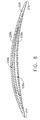
- FIGS 7 and 8 illustrate an alternative airfoil 212.
- the airfoil 212 is substantially similar to the airfoil 12 described above and is constructed from a body 226 and covers 228a, 228b.
- the airfoil 212 includes a leading edge 214, a trailing edge 216, a tip 218, a root 219, a convex suction side 220, and a concave pressure side 222.
- Recessed first and second pockets 230a, 230b are formed in the pressure side 222 and suction side 220 respectively to reduce the weight of the airfoil 212, and are sealed off by covers 228a and 228b.
- the body 226 may include a plurality of upstanding, spaced-apart ribs (not shown) disposed in the pockets 230a and 230b, similar to ribs 33 described above, or a filler material (not shown) as described above.
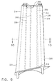
- FIGS 9 and 10 illustrate another alternative airfoil 312.
- the airfoil 312 includes a leading edge 314, a trailing edge 316, a tip 318, a root 319, a convex suction side 320, and a concave pressure side 322.
- the airfoil 312 is built up from individual components including a pressure side wall 324, a suction side wall 326, a leading edge spacer 328, a trailing edge spacer 330, and a plurality of internal spacers 332.
- the internal spacers 332 in the illustrated example are rectangular, spanwise ribs. However, the internal spacers 332 could comprise an array of pins or other similar elements.
- the individual components may be relatively simple, inexpensive structural elements.
- the pressure and suction side walls 324 and 326 may be aluminum sheet material
- the leading and trailing edge spacers 328 and 330 could be aluminum extrusions
- the internal spacers 332 could be cast, forged, or extruded from aluminum.
- Other arrangements of built-up components are possible.
- the pressure side wall 324, suction side wall 326, leading edge spacer 328, trailing edge spacer 330, and internal spacers 332 are retained in the appropriate positions using suitable tooling of a known type (not shown).
- the components are then joined by friction stir welding as described above.
- friction stir welds may be located as indicated by the exemplary arrows "F" in Figure 10.
- several overlapping adjacent welds may be made between the pressure and suction side walls 324 and 326 and the leading and trailing edge spacers 328 and 330.
- the suction and pressure side walls 324 and 326 extend past the leading and trailing edge spacers 328 and 330 to merge with each other at the leading and trailing edges 314 And 316, respectively.
- the pressure and suction side walls 324 and 326 could stop short of the leading and trailing edges in the chordwise direction, in which case the leading and trailing edge spacers 328 and 330 would define the leading and trailing edges of the airfoil 312. After the welding operation in complete, the airfoil 312 may be machined to form its final contours.
Landscapes
- Engineering & Computer Science (AREA)
- Mechanical Engineering (AREA)
- Architecture (AREA)
- General Engineering & Computer Science (AREA)
- Pressure Welding/Diffusion-Bonding (AREA)
- Turbine Rotor Nozzle Sealing (AREA)
- Structures Of Non-Positive Displacement Pumps (AREA)
Applications Claiming Priority (2)
| Application Number | Priority Date | Filing Date | Title |
|---|---|---|---|
| US846326 | 2004-05-14 | ||
| US10/846,326 US7189064B2 (en) | 2004-05-14 | 2004-05-14 | Friction stir welded hollow airfoils and method therefor |
Publications (1)
| Publication Number | Publication Date |
|---|---|
| EP1596036A1 true EP1596036A1 (fr) | 2005-11-16 |
Family
ID=34941251
Family Applications (1)
| Application Number | Title | Priority Date | Filing Date |
|---|---|---|---|
| EP05252903A Ceased EP1596036A1 (fr) | 2004-05-14 | 2005-05-11 | Aubes creuses soudées par friction-malaxage et procédé associé |
Country Status (3)
| Country | Link |
|---|---|
| US (1) | US7189064B2 (fr) |
| EP (1) | EP1596036A1 (fr) |
| JP (1) | JP2005325839A (fr) |
Cited By (35)
| Publication number | Priority date | Publication date | Assignee | Title |
|---|---|---|---|---|
| WO2008121539A3 (fr) * | 2007-03-19 | 2008-12-24 | Boeing Co | Procédé de fabrication d'une pièce à travailler par soudage par friction pour réduire l'occurrence de croissance de grain anormal |
| EP2093383A1 (fr) * | 2008-02-19 | 2009-08-26 | United Technologies Corporation | Aubes statoriques et ensemble des aubes statoriques |
| EP1939402A3 (fr) * | 2006-12-21 | 2010-05-05 | Rolls-Royce Deutschland Ltd & Co KG | Aube de soufflante en matériau composite pour un moteur à turbine à gaz |
| EP2182168A1 (fr) * | 2008-10-28 | 2010-05-05 | General Electric Company | Aube de turbine hybride fabriquée |
| EP2239083A1 (fr) * | 2009-03-31 | 2010-10-13 | United Technologies Corporation | Aube de turbune à renfort interne et procédé pour renforcer en interne une aube de turbine creuse pendant sa fabrication |
| WO2011060892A1 (fr) * | 2009-11-17 | 2011-05-26 | Werner Lange | Dispositif de criblage pour le nettoyage d'une suspension de matière fibreuse |
| WO2011064406A1 (fr) * | 2009-11-30 | 2011-06-03 | Snecma | Procede de realisation d' un renfort metallique d' aube de turbomachine |
| FR2953430A1 (fr) * | 2009-12-03 | 2011-06-10 | Snecma | Procede de realisation d’un renfort metallique d’aube de turbomachine |
| CN102094847A (zh) * | 2010-12-30 | 2011-06-15 | 北京理工大学 | 一种叶轮机械叶片与端壁融合设计方法 |
| EP1942253A3 (fr) * | 2006-12-29 | 2011-08-24 | General Electric Company | Aube de guidage et son procédé de fabrication |
| EP2366871A1 (fr) * | 2010-03-17 | 2011-09-21 | General Electric Company | Procédé et appareil pour conduit d'aube de sortie structurelle |
| EP1908920A3 (fr) * | 2006-09-27 | 2011-12-07 | General Electric Company | Aube fixe et turbine à gaz comprenant plusieurs de ces aubes |
| US8177513B2 (en) | 2009-02-18 | 2012-05-15 | General Electric Company | Method and apparatus for a structural outlet guide vane |
| EP1876324A3 (fr) * | 2006-07-06 | 2012-05-23 | Rolls-Royce Plc | Aube d'une turbine à gaz |
| EP1983160A3 (fr) * | 2007-04-16 | 2012-11-07 | United Technologies Corporation | Aube de distributeur de turbine à gaz |
| EP2243929A3 (fr) * | 2009-04-16 | 2013-06-12 | United Technologies Corporation | Aube de soufflante à structure hybride |
| WO2013103663A1 (fr) | 2012-01-04 | 2013-07-11 | United Technologies Corporation | Pale de ventilateur en aluminium avec protection soudée |
| CN103410777A (zh) * | 2013-08-19 | 2013-11-27 | 中山市奥美森工业有限公司 | 一种风扇叶片 |
| WO2014055110A1 (fr) | 2012-10-01 | 2014-04-10 | United Technologies Corporation | Aube directrice statique à canaux internes creux |
| CN103790639A (zh) * | 2013-12-26 | 2014-05-14 | 北京理工大学 | 一种叶轮机端区叶片前缘边条修型方法 |
| EP2764951A1 (fr) * | 2013-02-08 | 2014-08-13 | Rolls-Royce plc | Fabrication d'une aube creuse |
| WO2015058043A1 (fr) | 2013-10-18 | 2015-04-23 | United Technologies Corporation | Composant de moteur multipièces |
| CN104603398A (zh) * | 2012-09-12 | 2015-05-06 | 联合工艺公司 | 具有蜂窝填料的中空风扇叶片 |
| FR3024750A1 (fr) * | 2014-08-06 | 2016-02-12 | Snecma | Aube creuse composee de deux parties collees entre elles, notamment pour turbomachine |
| WO2016139088A1 (fr) * | 2015-03-03 | 2016-09-09 | Siemens Aktiengesellschaft | Pièce creuse massive avec tôle pour la création d'une cavité |
| FR3034131A1 (fr) * | 2015-03-24 | 2016-09-30 | Snecma | Etage d'aubes de stator pour une turbomachine |
| EP3085891A1 (fr) * | 2015-04-23 | 2016-10-26 | Rolls-Royce plc | Fabrication de surface portante creuse |
| EP2774716A3 (fr) * | 2013-03-08 | 2016-12-28 | General Electric Company | Procédé de production d'une aube creuse |
| EP2971537A4 (fr) * | 2013-03-15 | 2017-01-25 | United Technologies Corporation | Amortissement des vibrations pour aubes fixes structurelles |
| EP3153664A1 (fr) * | 2015-10-07 | 2017-04-12 | United Technologies Corporation | Construction de pale de ventilateur en aluminium comprenant un couvercle soude |
| GB2505845B (en) * | 2011-07-20 | 2018-02-21 | Snecma | Turbine engine vane plate seal |
| US10215027B2 (en) | 2012-01-04 | 2019-02-26 | United Technologies Corporation | Aluminum fan blade construction with welded cover |
| EP3617453A1 (fr) * | 2018-08-30 | 2020-03-04 | United Technologies Corporation | Pale de ventilateur dotée d'une gaine métallique fermée |
| EP3667018A1 (fr) * | 2018-12-13 | 2020-06-17 | United Technologies Corporation | Pale de soufflante pour moteur de turbine à gaz |
| EP3680059A1 (fr) * | 2019-01-08 | 2020-07-15 | United Technologies Corporation | Profil aérodynamique creux comportant des profils caténaires |
Families Citing this family (98)
| Publication number | Priority date | Publication date | Assignee | Title |
|---|---|---|---|---|
| US7487901B2 (en) * | 2004-07-29 | 2009-02-10 | The Boeing Company | Friction stir welding of joints with shims |
| US20070002686A1 (en) * | 2005-06-30 | 2007-01-04 | Spx Corporation | Mixing impeller and method with top and bottom skin elements |
| US9511446B2 (en) | 2014-12-17 | 2016-12-06 | Aeroprobe Corporation | In-situ interlocking of metals using additive friction stir processing |
| US9266191B2 (en) | 2013-12-18 | 2016-02-23 | Aeroprobe Corporation | Fabrication of monolithic stiffening ribs on metallic sheets |
| US8632850B2 (en) | 2005-09-26 | 2014-01-21 | Schultz-Creehan Holdings, Inc. | Friction fabrication tools |
| US9511445B2 (en) * | 2014-12-17 | 2016-12-06 | Aeroprobe Corporation | Solid state joining using additive friction stir processing |
| US7648336B2 (en) * | 2006-01-03 | 2010-01-19 | General Electric Company | Apparatus and method for assembling a gas turbine stator |
| US20080159856A1 (en) * | 2006-12-29 | 2008-07-03 | Thomas Ory Moniz | Guide vane and method of fabricating the same |
| US7607287B2 (en) * | 2007-05-29 | 2009-10-27 | United Technologies Corporation | Airfoil acoustic impedance control |
| US20080308197A1 (en) * | 2007-06-15 | 2008-12-18 | United Technologies Corporation | Secondary processing of structures derived from AL-RE-TM alloys |
| US20080308610A1 (en) * | 2007-06-15 | 2008-12-18 | United Technologies Corporation | Hollow structures formed with friction stir welding |
| US20100068550A1 (en) * | 2007-06-15 | 2010-03-18 | United Technologies Corporation | Hollow structures formed with friction stir welding |
| US20080311421A1 (en) * | 2007-06-15 | 2008-12-18 | United Technologies Corporation | Friction stir welded structures derived from AL-RE-TM alloys |
| EP2274131A4 (fr) * | 2007-09-19 | 2017-02-22 | Barnes Group Inc. | Soudage par diffusion |
| FR2921973B1 (fr) * | 2007-10-04 | 2011-04-29 | Snecma | Carter intermediaire de turboreacteur et turboreacteur |
| JP2009107461A (ja) * | 2007-10-30 | 2009-05-21 | Kinki Sharyo Co Ltd | 外板構造 |
| US8333552B2 (en) * | 2008-06-20 | 2012-12-18 | General Electric Company | Combined acoustic absorber and heat exchanging outlet guide vanes |
| US9938931B2 (en) * | 2008-12-23 | 2018-04-10 | General Electric Company | Combined surface cooler and acoustic absorber for turbomachines |
| JP2010190128A (ja) * | 2009-02-18 | 2010-09-02 | Toshiba Corp | タービン翼の浸食防止方法、及びタービン翼 |
| US8172541B2 (en) * | 2009-02-27 | 2012-05-08 | General Electric Company | Internally-damped airfoil and method therefor |
| US8585368B2 (en) | 2009-04-16 | 2013-11-19 | United Technologies Corporation | Hybrid structure airfoil |
| DE102009022181A1 (de) * | 2009-05-20 | 2010-11-25 | W & S Management Gmbh & Co. Kg | Ventilatorschaufel |
| CA2669000A1 (fr) * | 2009-06-18 | 2010-12-18 | Garold Toews | Trousse de modification de jambe de force d'aeronef avec un carenage aerodynamique |
| US9650897B2 (en) * | 2010-02-26 | 2017-05-16 | United Technologies Corporation | Hybrid metal fan blade |
| JP5647426B2 (ja) * | 2010-03-17 | 2014-12-24 | ゼネラル・エレクトリック・カンパニイ | 構造出口案内翼のための方法及び装置 |
| US8616834B2 (en) * | 2010-04-30 | 2013-12-31 | General Electric Company | Gas turbine engine airfoil integrated heat exchanger |
| US8740567B2 (en) * | 2010-07-26 | 2014-06-03 | United Technologies Corporation | Reverse cavity blade for a gas turbine engine |
| JP5411120B2 (ja) * | 2010-12-27 | 2014-02-12 | 株式会社日立製作所 | チタン合金製タービン翼 |
| US9004873B2 (en) | 2010-12-27 | 2015-04-14 | Rolls-Royce Corporation | Airfoil, turbomachine and gas turbine engine |
| US20120237351A1 (en) * | 2011-03-17 | 2012-09-20 | Weisse Michael A | Retention for bonded hollow fan blade cover |
| GB201115485D0 (en) | 2011-09-08 | 2011-10-26 | Rolls Royce Plc | An aerofoil assembly |
| US20130082088A1 (en) * | 2011-09-30 | 2013-04-04 | General Electric Company | Method and apparatus for repairing a component |
| US9233414B2 (en) * | 2012-01-31 | 2016-01-12 | United Technologies Corporation | Aluminum airfoil |
| US10982551B1 (en) | 2012-09-14 | 2021-04-20 | Raytheon Technologies Corporation | Turbomachine blade |
| US20140241897A1 (en) * | 2012-09-25 | 2014-08-28 | United Technologies Corporation | Aluminum brazing of hollow titanium fan blades |
| EP2900923B1 (fr) * | 2012-09-25 | 2019-12-25 | United Technologies Corporation | Réseau de profils aérodynamiques avec aubes directrices qui ont des géométries différentes associées à des classes géométriques |
| US9441496B2 (en) * | 2012-09-26 | 2016-09-13 | United Technologies Corporation | Structural guide vane internal topology |
| ITTV20120204A1 (it) * | 2012-10-30 | 2014-05-01 | Pietro Rosa T B M S R L | Metodo di costruzione di una paletta alleggerita per turbomacchine |
| WO2014078467A2 (fr) * | 2012-11-19 | 2014-05-22 | United Technologies Corporation | Réacteur à double flux à engrenages ayant des aubes de soufflante conçues pour réaliser un écoulement laminaire |
| EP2735706B8 (fr) * | 2012-11-21 | 2016-12-07 | Safran Aero Booster S.A. | Redresseur à aubes de compresseur de turbomachine axiale et procédé de fabrication |
| US9453418B2 (en) * | 2012-12-17 | 2016-09-27 | United Technologies Corporation | Hollow airfoil with composite cover and foam filler |
| ITTV20130029A1 (it) | 2013-02-28 | 2014-08-29 | Pietro Rosa T B M S R L | Paletta per turbomacchine e relativo metodo di costruzione |
| ITTV20130031A1 (it) | 2013-02-28 | 2014-08-29 | Pietro Rosa T B M S R L | Paletta per turbomacchine e relativo metodo di costruzione |
| US10060266B2 (en) * | 2013-03-08 | 2018-08-28 | United Technologies Corporation | Covers for cavities in aircraft fan blades |
| JP6167677B2 (ja) | 2013-06-06 | 2017-07-26 | 株式会社Ihi | ファンにおける翼及びファン |
| US10294958B2 (en) | 2013-09-24 | 2019-05-21 | United Technologies Corporation | Fan blade assembly |
| US10145245B2 (en) | 2013-09-24 | 2018-12-04 | United Technologies Corporation | Bonded multi-piece gas turbine engine component |
| WO2015102715A2 (fr) * | 2013-10-30 | 2015-07-09 | United Technologies Corporation | Nervures composites de pale de ventilateur |
| US10808718B2 (en) | 2013-10-30 | 2020-10-20 | Raytheon Technologies Corporation | Fan blade composite segments |
| US10458249B2 (en) | 2013-11-08 | 2019-10-29 | United Technologies Corporation | Bonded multi-piece gas turbine engine component |
| EP3074605B1 (fr) | 2013-11-26 | 2018-12-05 | United Technologies Corporation | Pale de ventilateur comportant un couvercle de pale de ventilateur segmenté |
| US10443612B2 (en) | 2013-12-16 | 2019-10-15 | United Technologies Corporation | Hollow fan blade with stir welded cover support |
| US9896941B2 (en) * | 2014-01-16 | 2018-02-20 | United Technologies Corporation | Fan blade composite cover with tapered edges |
| US9804058B2 (en) * | 2014-02-27 | 2017-10-31 | Pratt & Whitney Canada Corp. | Method of facilitating visual detection of a crack in a component of a gas turbine engine |
| US10660236B2 (en) | 2014-04-08 | 2020-05-19 | General Electric Company | Systems and methods for using additive manufacturing for thermal management |
| US9656761B2 (en) * | 2014-04-30 | 2017-05-23 | The Boeing Company | Lipskin for a nacelle and methods of making the same |
| US9604438B2 (en) | 2014-04-30 | 2017-03-28 | The Boeing Company | Methods and apparatus for noise attenuation in an engine nacelle |
| US9938852B2 (en) | 2014-04-30 | 2018-04-10 | The Boeing Company | Noise attenuating lipskin assembly and methods of assembling the same |
| US9708072B2 (en) | 2014-04-30 | 2017-07-18 | The Boeing Company | Aircraft engine nacelle bulkheads and methods of assembling the same |
| US20160177732A1 (en) * | 2014-07-22 | 2016-06-23 | United Technologies Corporation | Hollow fan blade for a gas turbine engine |
| GB2532507B (en) * | 2014-11-24 | 2017-07-12 | Rolls Royce Plc | Fluidfoil |
| US10356945B2 (en) | 2015-01-08 | 2019-07-16 | General Electric Company | System and method for thermal management using vapor chamber |
| BE1022809B1 (fr) * | 2015-03-05 | 2016-09-13 | Techspace Aero S.A. | Aube composite de compresseur de turbomachine axiale |
| US9909448B2 (en) | 2015-04-15 | 2018-03-06 | General Electric Company | Gas turbine engine component with integrated heat pipe |
| EP3351651B1 (fr) * | 2015-09-14 | 2022-01-05 | Mitsubishi Power, Ltd. | Procédé de fabrication d'aubes de rotor de turbine |
| US9845728B2 (en) * | 2015-10-15 | 2017-12-19 | Rohr, Inc. | Forming a nacelle inlet for a turbine engine propulsion system |
| US20170198592A1 (en) * | 2016-01-11 | 2017-07-13 | General Electric Company | Methods for mounting a turbine subcomponent to a turbine component |
| US10260523B2 (en) * | 2016-04-06 | 2019-04-16 | Rolls-Royce North American Technologies Inc. | Fluid cooling system integrated with outlet guide vane |
| US10209009B2 (en) | 2016-06-21 | 2019-02-19 | General Electric Company | Heat exchanger including passageways |
| GB2551750B (en) * | 2016-06-29 | 2020-03-25 | Rolls Royce Plc | Cavity sealing |
| US10408227B2 (en) * | 2016-07-13 | 2019-09-10 | Rolls-Royce Corporation | Airfoil with stress-reducing fillet adapted for use in a gas turbine engine |
| US20180038386A1 (en) * | 2016-08-08 | 2018-02-08 | United Technologies Corporation | Fan blade with composite cover |
| US11131314B2 (en) * | 2016-09-14 | 2021-09-28 | Raytheon Technologies Corporation | Fan blade with structural spar and integrated leading edge |
| FR3061512B1 (fr) * | 2017-01-05 | 2020-10-23 | Safran Aircraft Engines | Element radial de stator de turbomachine comportant un raidisseur |
| US11199096B1 (en) | 2017-01-17 | 2021-12-14 | Raytheon Technologies Corporation | Turbomachine blade |
| US11261737B1 (en) | 2017-01-17 | 2022-03-01 | Raytheon Technologies Corporation | Turbomachine blade |
| US10329919B2 (en) * | 2017-04-07 | 2019-06-25 | United Technologies Corporation | Airfoil structure and method of manufacture |
| US10502064B2 (en) * | 2017-08-07 | 2019-12-10 | United Technologies Corporation | Power beam welded cavity-back titanium hollow fan blade |
| AU2018359514C1 (en) | 2017-10-31 | 2021-05-27 | MELD Manufacturing Corporation | Solid-state additive manufacturing system and material compositions and structures |
| US10793943B2 (en) | 2018-03-15 | 2020-10-06 | Raytheon Technologies Corporation | Method of producing a gas turbine engine component |
| US10828718B2 (en) * | 2018-06-14 | 2020-11-10 | Raytheon Technologies Corporation | Installation of waterjet vent holes into vertical walls of cavity-back airfoils |
| US10919116B2 (en) * | 2018-06-14 | 2021-02-16 | Raytheon Technologies Corporation | Installation of laser vent holes into vertical walls of cavity-back airfoils |
| US11433990B2 (en) | 2018-07-09 | 2022-09-06 | Rohr, Inc. | Active laminar flow control system with composite panel |
| US11236619B2 (en) | 2019-05-07 | 2022-02-01 | Raytheon Technologies Corporation | Multi-cover gas turbine engine component |
| US11174737B2 (en) | 2019-06-12 | 2021-11-16 | Raytheon Technologies Corporation | Airfoil with cover for gas turbine engine |
| US11248477B2 (en) | 2019-08-02 | 2022-02-15 | Raytheon Technologies Corporation | Hybridized airfoil for a gas turbine engine |
| US11260976B2 (en) | 2019-11-15 | 2022-03-01 | General Electric Company | System for reducing thermal stresses in a leading edge of a high speed vehicle |
| US11427330B2 (en) | 2019-11-15 | 2022-08-30 | General Electric Company | System and method for cooling a leading edge of a high speed vehicle |
| US11352120B2 (en) | 2019-11-15 | 2022-06-07 | General Electric Company | System and method for cooling a leading edge of a high speed vehicle |
| US11267551B2 (en) | 2019-11-15 | 2022-03-08 | General Electric Company | System and method for cooling a leading edge of a high speed vehicle |
| US11260953B2 (en) | 2019-11-15 | 2022-03-01 | General Electric Company | System and method for cooling a leading edge of a high speed vehicle |
| US12040690B2 (en) | 2020-08-31 | 2024-07-16 | General Electric Company | Cooling a stator housing of an electric machine |
| US11745847B2 (en) | 2020-12-08 | 2023-09-05 | General Electric Company | System and method for cooling a leading edge of a high speed vehicle |
| US11407488B2 (en) | 2020-12-14 | 2022-08-09 | General Electric Company | System and method for cooling a leading edge of a high speed vehicle |
| US11577817B2 (en) | 2021-02-11 | 2023-02-14 | General Electric Company | System and method for cooling a leading edge of a high speed vehicle |
| US11867084B1 (en) | 2022-12-20 | 2024-01-09 | Rtx Corporation | Hollow airfoil construction using cover subassembly |
| FR3153551A1 (fr) * | 2023-09-28 | 2025-04-04 | Safran Aircraft Engines | Pièce forgée pour la fabrication d’un bras structural de carter intermédiaire de turboréacteur à double flux et procédé de fabrication d’un tel bras structural |
| US20250243766A1 (en) * | 2024-01-31 | 2025-07-31 | Honeywell International Inc. | Polymer-metal composite stator vanes and methods for manufacturing the same |
Citations (6)
| Publication number | Priority date | Publication date | Assignee | Title |
|---|---|---|---|---|
| US5725355A (en) * | 1996-12-10 | 1998-03-10 | General Electric Company | Adhesive bonded fan blade |
| EP0867621A1 (fr) * | 1996-10-14 | 1998-09-30 | Daikin Industries, Limited | Procede de fabrication de pale creuse et pale creuse fabriquee au moyen de ce procede |
| US20010007634A1 (en) * | 1998-05-20 | 2001-07-12 | Beyer James R. | Hollow blade for hydraulic turbine or pump |
| EP1291115A2 (fr) * | 2001-08-29 | 2003-03-12 | The Boeing Company | Interface préparatoire pour joints soudés |
| JP2004017097A (ja) * | 2002-06-17 | 2004-01-22 | Shin Meiwa Ind Co Ltd | 中空組立構造物、航空機の動翼、及び中空組立構造物の製造方法 |
| EP1462609A1 (fr) * | 2003-03-28 | 2004-09-29 | Snecma Moteurs | Aube allégée de turbomachine et son procédé de fabrication |
Family Cites Families (18)
| Publication number | Priority date | Publication date | Assignee | Title |
|---|---|---|---|---|
| US1762352A (en) * | 1928-10-09 | 1930-06-10 | Westinghouse Electric & Mfg Co | Turbine blade |
| US1992338A (en) * | 1931-06-05 | 1935-02-26 | Bendix Aviat Corp | Propeller blade and method of making the same |
| US2698666A (en) * | 1952-07-01 | 1955-01-04 | Gen Motors Corp | Propeller blade |
| US3359936A (en) * | 1966-06-23 | 1967-12-26 | Wilson Shipyard Inc | Hydrofoil |
| US3695778A (en) * | 1970-09-18 | 1972-10-03 | Trw Inc | Turbine blade |
| US4820117A (en) * | 1987-07-09 | 1989-04-11 | United Technologies Corporation | Crossed I-beam structural strut |
| US5099573A (en) * | 1990-06-27 | 1992-03-31 | Compressor Components Textron Inc. | Method of making hollow articles |
| US5469618A (en) * | 1993-12-06 | 1995-11-28 | General Electric Company | Method for manufacturing hollow airfoils (two-piece concept) |
| US5655883A (en) * | 1995-09-25 | 1997-08-12 | General Electric Company | Hybrid blade for a gas turbine |
| DE19542080C1 (de) * | 1995-11-11 | 1997-01-30 | Mtu Muenchen Gmbh | Schaufelblatt für Turbotriebwerke zur Herstellung von Laufrädern mit integralen Hohlschaufeln |
| JPH10193143A (ja) * | 1997-01-17 | 1998-07-28 | Showa Alum Corp | 摩擦撹拌接合法 |
| GB9713209D0 (en) * | 1997-06-20 | 1997-08-27 | British Aerospace | Friction welding metal components |
| JPH1147959A (ja) * | 1997-07-31 | 1999-02-23 | Mitsubishi Heavy Ind Ltd | 外板の製造方法 |
| JP2001047260A (ja) * | 1999-08-06 | 2001-02-20 | Mitsubishi Heavy Ind Ltd | 長手方向に断面形状が変化している部材の製造方法、その製造方法により製造された部材およびその部材を用いた航空機 |
| US6453670B1 (en) * | 2000-12-21 | 2002-09-24 | Delphi Technologies, Inc. | Two-piece stationary seal master cylinder |
| US6676004B1 (en) * | 2001-02-13 | 2004-01-13 | Edison Welding Institute, Inc. | Tool for friction stir welding |
| US6537682B2 (en) * | 2001-03-27 | 2003-03-25 | The Boeing Company | Application of friction stir welding to superplastically formed structural assemblies |
| US6484924B1 (en) * | 2001-08-14 | 2002-11-26 | The Boeing Company | Method and apparatus for backing up a friction stir weld joint |
-
2004
- 2004-05-14 US US10/846,326 patent/US7189064B2/en not_active Expired - Fee Related
-
2005
- 2005-05-11 EP EP05252903A patent/EP1596036A1/fr not_active Ceased
- 2005-05-13 JP JP2005140766A patent/JP2005325839A/ja active Pending
Patent Citations (6)
| Publication number | Priority date | Publication date | Assignee | Title |
|---|---|---|---|---|
| EP0867621A1 (fr) * | 1996-10-14 | 1998-09-30 | Daikin Industries, Limited | Procede de fabrication de pale creuse et pale creuse fabriquee au moyen de ce procede |
| US5725355A (en) * | 1996-12-10 | 1998-03-10 | General Electric Company | Adhesive bonded fan blade |
| US20010007634A1 (en) * | 1998-05-20 | 2001-07-12 | Beyer James R. | Hollow blade for hydraulic turbine or pump |
| EP1291115A2 (fr) * | 2001-08-29 | 2003-03-12 | The Boeing Company | Interface préparatoire pour joints soudés |
| JP2004017097A (ja) * | 2002-06-17 | 2004-01-22 | Shin Meiwa Ind Co Ltd | 中空組立構造物、航空機の動翼、及び中空組立構造物の製造方法 |
| EP1462609A1 (fr) * | 2003-03-28 | 2004-09-29 | Snecma Moteurs | Aube allégée de turbomachine et son procédé de fabrication |
Non-Patent Citations (1)
| Title |
|---|
| PATENT ABSTRACTS OF JAPAN vol. 2003, no. 12 5 December 2003 (2003-12-05) * |
Cited By (54)
| Publication number | Priority date | Publication date | Assignee | Title |
|---|---|---|---|---|
| EP1876324A3 (fr) * | 2006-07-06 | 2012-05-23 | Rolls-Royce Plc | Aube d'une turbine à gaz |
| EP1908920A3 (fr) * | 2006-09-27 | 2011-12-07 | General Electric Company | Aube fixe et turbine à gaz comprenant plusieurs de ces aubes |
| US8251664B2 (en) | 2006-12-21 | 2012-08-28 | Rolls-Royce Deutschland Ltd Co KG | Fan blade for a gas-turbine engine |
| EP1939402A3 (fr) * | 2006-12-21 | 2010-05-05 | Rolls-Royce Deutschland Ltd & Co KG | Aube de soufflante en matériau composite pour un moteur à turbine à gaz |
| EP1942253A3 (fr) * | 2006-12-29 | 2011-08-24 | General Electric Company | Aube de guidage et son procédé de fabrication |
| GB2461208B (en) * | 2007-03-19 | 2011-04-20 | Boeing Co | Method for manufacturing a workpiece by friction welding to reduce the occurence of abnormal grain growth |
| WO2008121539A3 (fr) * | 2007-03-19 | 2008-12-24 | Boeing Co | Procédé de fabrication d'une pièce à travailler par soudage par friction pour réduire l'occurrence de croissance de grain anormal |
| GB2461208A (en) * | 2007-03-19 | 2009-12-30 | Boeing Co | Method for manufacturing a workpiece by friction welding to reduce the occurence of abnormal grain growth |
| EP1983160A3 (fr) * | 2007-04-16 | 2012-11-07 | United Technologies Corporation | Aube de distributeur de turbine à gaz |
| US8511983B2 (en) | 2008-02-19 | 2013-08-20 | United Technologies Corporation | LPC exit guide vane and assembly |
| EP2093383A1 (fr) * | 2008-02-19 | 2009-08-26 | United Technologies Corporation | Aubes statoriques et ensemble des aubes statoriques |
| EP2182168A1 (fr) * | 2008-10-28 | 2010-05-05 | General Electric Company | Aube de turbine hybride fabriquée |
| US8177513B2 (en) | 2009-02-18 | 2012-05-15 | General Electric Company | Method and apparatus for a structural outlet guide vane |
| EP2239083A1 (fr) * | 2009-03-31 | 2010-10-13 | United Technologies Corporation | Aube de turbune à renfort interne et procédé pour renforcer en interne une aube de turbine creuse pendant sa fabrication |
| EP2243929A3 (fr) * | 2009-04-16 | 2013-06-12 | United Technologies Corporation | Aube de soufflante à structure hybride |
| WO2011060892A1 (fr) * | 2009-11-17 | 2011-05-26 | Werner Lange | Dispositif de criblage pour le nettoyage d'une suspension de matière fibreuse |
| WO2011064406A1 (fr) * | 2009-11-30 | 2011-06-03 | Snecma | Procede de realisation d' un renfort metallique d' aube de turbomachine |
| EP2998062A1 (fr) * | 2009-11-30 | 2016-03-23 | Snecma | Procédé de réalisation d'un renfort métallique d'aube de turbomachine |
| FR2953430A1 (fr) * | 2009-12-03 | 2011-06-10 | Snecma | Procede de realisation d’un renfort metallique d’aube de turbomachine |
| EP2366871A1 (fr) * | 2010-03-17 | 2011-09-21 | General Electric Company | Procédé et appareil pour conduit d'aube de sortie structurelle |
| CN102094847A (zh) * | 2010-12-30 | 2011-06-15 | 北京理工大学 | 一种叶轮机械叶片与端壁融合设计方法 |
| GB2505845B (en) * | 2011-07-20 | 2018-02-21 | Snecma | Turbine engine vane plate seal |
| WO2013103663A1 (fr) | 2012-01-04 | 2013-07-11 | United Technologies Corporation | Pale de ventilateur en aluminium avec protection soudée |
| US10215027B2 (en) | 2012-01-04 | 2019-02-26 | United Technologies Corporation | Aluminum fan blade construction with welded cover |
| EP2800876A4 (fr) * | 2012-01-04 | 2015-12-02 | United Technologies Corp | Pale de ventilateur en aluminium avec protection soudée |
| CN104603398A (zh) * | 2012-09-12 | 2015-05-06 | 联合工艺公司 | 具有蜂窝填料的中空风扇叶片 |
| CN104603398B (zh) * | 2012-09-12 | 2017-03-08 | 联合工艺公司 | 具有蜂窝填料的中空风扇叶片 |
| EP2904252A4 (fr) * | 2012-10-01 | 2015-12-09 | United Technologies Corp | Aube directrice statique à canaux internes creux |
| WO2014055110A1 (fr) | 2012-10-01 | 2014-04-10 | United Technologies Corporation | Aube directrice statique à canaux internes creux |
| EP2904252B1 (fr) | 2012-10-01 | 2017-12-06 | United Technologies Corporation | Aube directrice statique à canaux internes creux |
| EP2764951A1 (fr) * | 2013-02-08 | 2014-08-13 | Rolls-Royce plc | Fabrication d'une aube creuse |
| US9879545B2 (en) | 2013-02-08 | 2018-01-30 | Rolls-Royce Plc | Manufacture of hollow aerofoil |
| EP2774716A3 (fr) * | 2013-03-08 | 2016-12-28 | General Electric Company | Procédé de production d'une aube creuse |
| EP2971537A4 (fr) * | 2013-03-15 | 2017-01-25 | United Technologies Corporation | Amortissement des vibrations pour aubes fixes structurelles |
| US9957824B2 (en) | 2013-03-15 | 2018-05-01 | United Technologies Corporation | Vibration damping for structural guide vanes |
| CN103410777A (zh) * | 2013-08-19 | 2013-11-27 | 中山市奥美森工业有限公司 | 一种风扇叶片 |
| WO2015058043A1 (fr) | 2013-10-18 | 2015-04-23 | United Technologies Corporation | Composant de moteur multipièces |
| US11143034B2 (en) | 2013-10-18 | 2021-10-12 | Raytheon Technologies Corporation | Multiple piece engine component |
| US10329918B2 (en) | 2013-10-18 | 2019-06-25 | United Technologies Corporation | Multiple piece engine component |
| EP3058177A4 (fr) * | 2013-10-18 | 2017-03-15 | United Technologies Corporation | Composant de moteur multipièces |
| EP4306233A3 (fr) * | 2013-10-18 | 2024-04-03 | RTX Corporation | Procédé de formation d'un composant d'un moteur à turbine à gaz |
| CN103790639B (zh) * | 2013-12-26 | 2016-11-16 | 北京理工大学 | 一种叶轮机端区叶片前缘边条修型方法 |
| CN103790639A (zh) * | 2013-12-26 | 2014-05-14 | 北京理工大学 | 一种叶轮机端区叶片前缘边条修型方法 |
| FR3024750A1 (fr) * | 2014-08-06 | 2016-02-12 | Snecma | Aube creuse composee de deux parties collees entre elles, notamment pour turbomachine |
| CN107405735A (zh) * | 2015-03-03 | 2017-11-28 | 西门子公司 | 具有用于产生空腔的板的坚固的空心的构件 |
| WO2016139088A1 (fr) * | 2015-03-03 | 2016-09-09 | Siemens Aktiengesellschaft | Pièce creuse massive avec tôle pour la création d'une cavité |
| FR3034131A1 (fr) * | 2015-03-24 | 2016-09-30 | Snecma | Etage d'aubes de stator pour une turbomachine |
| EP3085891A1 (fr) * | 2015-04-23 | 2016-10-26 | Rolls-Royce plc | Fabrication de surface portante creuse |
| EP3153664A1 (fr) * | 2015-10-07 | 2017-04-12 | United Technologies Corporation | Construction de pale de ventilateur en aluminium comprenant un couvercle soude |
| US11009036B2 (en) | 2018-08-30 | 2021-05-18 | Raytheon Technologies Corporation | Fan blade having closed metal sheath |
| EP3617453A1 (fr) * | 2018-08-30 | 2020-03-04 | United Technologies Corporation | Pale de ventilateur dotée d'une gaine métallique fermée |
| EP3667018A1 (fr) * | 2018-12-13 | 2020-06-17 | United Technologies Corporation | Pale de soufflante pour moteur de turbine à gaz |
| US10808541B2 (en) | 2018-12-13 | 2020-10-20 | Raytheon Technologies Corporation | Fan blade for a gas turbine engine |
| EP3680059A1 (fr) * | 2019-01-08 | 2020-07-15 | United Technologies Corporation | Profil aérodynamique creux comportant des profils caténaires |
Also Published As
| Publication number | Publication date |
|---|---|
| JP2005325839A (ja) | 2005-11-24 |
| US20050254955A1 (en) | 2005-11-17 |
| US7189064B2 (en) | 2007-03-13 |
Similar Documents
| Publication | Publication Date | Title |
|---|---|---|
| US7189064B2 (en) | Friction stir welded hollow airfoils and method therefor | |
| US6219916B1 (en) | Method for linear friction welding and product made by such method | |
| US5330092A (en) | Multiple density sandwich structures and method of fabrication | |
| US7334997B2 (en) | Hybrid blisk | |
| US5197190A (en) | Fabrication of repair method for an integrally bladed rotor | |
| US7520055B2 (en) | Method for manufacturing a stator or rotor component | |
| CN101985200B (zh) | 用于涡轮机翼的加强边缘的制造方法 | |
| US9453418B2 (en) | Hollow airfoil with composite cover and foam filler | |
| EP2243929A2 (fr) | Aube de soufflante à structure hybride | |
| JP2007507644A (ja) | ガスタービンブレード又はブレード一体化ガスタービンロータを製造及び/又は修理する際に、ブレードをブレード付け根部もしくはロータディスクへ接合する方法 | |
| EP2586972A2 (fr) | Dispositifs à surface portante, éléments du bord d'attaque et procédés de fabrication de ces éléments | |
| JP2001082388A (ja) | 塑性成形ハイブリッド翼形部 | |
| US11852035B2 (en) | Multi-cover gas turbine engine component | |
| CN1978868B (zh) | 双层顶盖 | |
| EP1557532A2 (fr) | Aube creuse de soufflante pour moteur à turbine à gaz, moteur à turbine à gaz ainsi que procédé pour faire une telle aube creuse de soufflante | |
| US20050044708A1 (en) | Method for manufacturing a hollow blade for a stator or rotor component | |
| EP1557531A2 (fr) | Aube creuse de soufflante pour moteur à turbine à gaz | |
| EP1557529A2 (fr) | Aube creuse de soufflante pour turbomachine | |
| JPH11324607A5 (fr) | ||
| EP3067153A1 (fr) | Fabrication de surface portante creuse | |
| US5503532A (en) | Diffusion bonded airfoil and method | |
| EP2412930A2 (fr) | Segment statorique de turbine et son procédé de réparation | |
| US7387493B2 (en) | Impeller with widened blades | |
| Coombe et al. | Some Present Uses and Future Prospects of Titanium in Airframes | |
| JPH0122066B2 (fr) |
Legal Events
| Date | Code | Title | Description |
|---|---|---|---|
| PUAI | Public reference made under article 153(3) epc to a published international application that has entered the european phase |
Free format text: ORIGINAL CODE: 0009012 |
|
| AK | Designated contracting states |
Kind code of ref document: A1 Designated state(s): AT BE BG CH CY CZ DE DK EE ES FI FR GB GR HU IE IS IT LI LT LU MC NL PL PT RO SE SI SK TR |
|
| AX | Request for extension of the european patent |
Extension state: AL BA HR LV MK YU |
|
| 17P | Request for examination filed |
Effective date: 20060516 |
|
| AKX | Designation fees paid |
Designated state(s): DE FR GB IT |
|
| 17Q | First examination report despatched |
Effective date: 20070111 |
|
| STAA | Information on the status of an ep patent application or granted ep patent |
Free format text: STATUS: THE APPLICATION HAS BEEN REFUSED |
|
| 18R | Application refused |
Effective date: 20081218 |