EP2182168A1 - Aube de turbine hybride fabriquée - Google Patents
Aube de turbine hybride fabriquée Download PDFInfo
- Publication number
- EP2182168A1 EP2182168A1 EP09173888A EP09173888A EP2182168A1 EP 2182168 A1 EP2182168 A1 EP 2182168A1 EP 09173888 A EP09173888 A EP 09173888A EP 09173888 A EP09173888 A EP 09173888A EP 2182168 A1 EP2182168 A1 EP 2182168A1
- Authority
- EP
- European Patent Office
- Prior art keywords
- blade
- turbine
- support structure
- alloy
- based alloy
- Prior art date
- Legal status (The legal status is an assumption and is not a legal conclusion. Google has not performed a legal analysis and makes no representation as to the accuracy of the status listed.)
- Withdrawn
Links
Images

Classifications
-
- F—MECHANICAL ENGINEERING; LIGHTING; HEATING; WEAPONS; BLASTING
- F01—MACHINES OR ENGINES IN GENERAL; ENGINE PLANTS IN GENERAL; STEAM ENGINES
- F01D—NON-POSITIVE DISPLACEMENT MACHINES OR ENGINES, e.g. STEAM TURBINES
- F01D5/00—Blades; Blade-carrying members; Heating, heat-insulating, cooling or antivibration means on the blades or the members
- F01D5/12—Blades
- F01D5/14—Form or construction
- F01D5/147—Construction, i.e. structural features, e.g. of weight-saving hollow blades
-
- F—MECHANICAL ENGINEERING; LIGHTING; HEATING; WEAPONS; BLASTING
- F05—INDEXING SCHEMES RELATING TO ENGINES OR PUMPS IN VARIOUS SUBCLASSES OF CLASSES F01-F04
- F05D—INDEXING SCHEME FOR ASPECTS RELATING TO NON-POSITIVE-DISPLACEMENT MACHINES OR ENGINES, GAS-TURBINES OR JET-PROPULSION PLANTS
- F05D2250/00—Geometry
- F05D2250/20—Three-dimensional
- F05D2250/28—Three-dimensional patterned
- F05D2250/283—Three-dimensional patterned honeycomb
-
- Y—GENERAL TAGGING OF NEW TECHNOLOGICAL DEVELOPMENTS; GENERAL TAGGING OF CROSS-SECTIONAL TECHNOLOGIES SPANNING OVER SEVERAL SECTIONS OF THE IPC; TECHNICAL SUBJECTS COVERED BY FORMER USPC CROSS-REFERENCE ART COLLECTIONS [XRACs] AND DIGESTS
- Y02—TECHNOLOGIES OR APPLICATIONS FOR MITIGATION OR ADAPTATION AGAINST CLIMATE CHANGE
- Y02T—CLIMATE CHANGE MITIGATION TECHNOLOGIES RELATED TO TRANSPORTATION
- Y02T50/00—Aeronautics or air transport
- Y02T50/60—Efficient propulsion technologies, e.g. for aircraft
Definitions
- the invention herein relates to rotating components for a turbine and in particular to embodiments of turbine blades.
- Turbine engines such as those used for aircraft propulsion and power generation, rely upon arrays of aerodynamic blades for turning of a central shaft.
- the blade may be subjected to thermal stress arising from combustion gases.
- all of the blades also referred to as "buckets" are subject to mechanical stress associated with rotation about a central axis of the shaft.
- the invention includes a blade for a turbine, the blade including: a support structure of high strength material, as a central portion of the blade, the support structure including a root and a body extending to a tip, the body providing a leading edge, a trailing edge and a mounting section; and a honeycomb skin attached to the mounting section for providing a lightweight airfoil portion of the blade.
- the invention includes a method for fabricating a blade for a turbine, the method including: using a high strength material, forming a central portion of the blade, the central portion including a root and a body extending to a tip, the body providing a leading edge, a trailing edge and mounting section; and attaching a honeycomb skin to a surface of the central portion to provide an airfoil of the blade.
- the invention includes a turbine including: at least one blade including a support structure of high strength material, the support structure including a root and a body extending to a tip, the body providing a leading edge, a trailing edge and a mounting section; and a honeycomb skin attached to the mounting section for providing a lightweight airfoil portion of the blade.
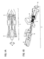
- FIG. 1 there are shown two examples of a turbine 1 suited for practice of the invention.
- FIG. 1A there is shown an aircraft gas turbine 1.
- the aircraft gas turbine 1 includes various turbine blades, or “buckets.”
- the blades are generally aerodynamic structures mounted circumferentially about a shaft which is centered in an axis of rotation.
- a compressor 2 having a plurality of blades for compressing intake air.
- a low-pressure-turbine 3 includes a plurality of blades for receiving combustion gases from a combustion chamber within the turbine 1.
- FIG. 1B there is shown a power generation gas turbine 1.
- the power generation gas turbine 1 also includes the compressor 2, and may further include additional pluralities of blades, such as in a latter stage 6 and within a steam turbine 5. Also shown, for perspective, is a generator 4 used for generation of electrical power from rotation of the shaft of the power generation gas turbine 1. In either embodiment of the turbine 1, the various blades will rotate about an axis of rotation, R.
- compressor low pressure turbine
- steam turbine steam turbine
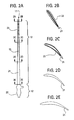
- the blade 10 includes a section generally referred to as a "tip" 11, a section generally referred to as a "root” 12, and a section generally referred to as a "body” 13.
- the tip 11 When installed in the gas turbine 1, the tip 11 is generally located near an inner wall of a housing to the gas turbine 1, and may be located within grooves or other such devices useful for ensuring alignment, strength, efficiency or other aspects of operation.
- the root 12 is a section of the blade 10 that provides for anchoring of the blade 10 about the central shaft which is centered in the axis of rotation, R.
- the body 13 of the blade 10 is of an aerodynamic form and provides for at least one of compressing gas in the compressor 2, or receiving expanding gas, such as in the low pressure turbine 3, latter stages 6 or the steam turbine 5.
- the blade 10 includes a high strength support structure 21.
- the high strength support structure 21 assumes an aerodynamic shape near the root (refer to sections 2D-2D and 2C-2C in FIG. 2 ), and gradually diminishes in stature to what is generally a flat or substantially flat spine for the blade 10 (refer to sections 2B-2B and then 2A-2A in FIG. 2 ).
- the high strength support structure 21 is of a curved, slightly offset or of some other shape such that it is of a profile that is reduced or smaller than the profile for a completed blade 10.
- the tapering down of the high strength support structure 21 provides for a complimentary use of a honeycomb skin 23 which is coupled to the surface of the high strength support structure 21.
- the high strength support structure 21 may be referred to as a "core” or a “central portion” and by other similar terms.
- the honeycomb skin 23 may be referred to as providing a "airfoil” “an aerodynamic portion” and by other similar terms.
- Exemplary materials for the high strength support structure 21 and the honeycomb skin 23 include alloys such as a superalloy, a cobalt based alloy, a hardened alloy, a carbide based alloy, a nickel based alloy, an undirectionally solidified alloy (in other words, an alloy solidified without a preferred direction), an iron based alloy, a wrought austenitic stainless steel, a martensitic stainless steel, a ferritic stainless steel, a carbon steel, a common titanium alloy and an inter-metallic titanium alloy.
- a ceramic matrix composite material may be used.
- the high strength support structure 21 may be fabricated using various techniques, such as, without limitation, casting, forging, welding (such as to assemble various parts), brazing, sanding, polishing, etching and the like. Fabrication of the high strength support structure 21 may include execution of combinations of techniques and through various stages of assembly.
- the high strength support structure 21 includes one to many perforations (not shown). In further embodiments, the high strength support structure 21 may include at least one of concave and convex gripping features. In such embodiments, the perforations and the gripping features 24 (examples being shown in FIG. 4B and 5C ) may provide for reduced weight, improved attaching of the honeycomb skin 23 and other such enhancements.
- the honeycomb skin 23 may be attached to the high strength support structure 21 by use of various techniques.
- the honeycomb skin 23 may be at least one of brazed, such as by using braze tapes or powder, welded such as by fusion welding, bonded, such as by diffusion bonding and attached by other techniques.
- the honeycomb skin 23 is attached to the high strength support structure 21 using techniques that provide for durable operation of the blade 10 under normal operating conditions.
- the high strength support structure 21 generally includes a section for a leading edge 31 and another section for a trailing edge 32. As this cross-sectional view is of the blade 10 near the tip 11, an intermediate area between the leading edge 31 and the trailing edge 32 is generally flat, or substantially flat. The flat or substantially flat portion of intermediate area is provided as a mounting section 33 for mounting of the honeycomb skin 23.
- the leading edge 31 includes an overlap 41.
- the trailing edge 32 includes the overlap 41.
- the overlap 41 may be formed of a comparatively thin layer of material used in the honeycomb skin 23.
- at least one of the leading edge 31 and the trailing edge 32 include a recessed zone for accepting the overlap 41 while providing for a smooth transition to material of the high strength support structure 21.
- the recessed zone may be included by a variety of techniques, such as, for example, machining, casting, etching and the like. Included in the recessed zone may be at least one gripping feature 24.
- the gripping feature 24 generally provides an irregular surface feature to improve the attachment of the overlap 41 or the honeycomb skin 23.
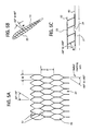
- FIG. 5A provides a side cross-sectional view of the honeycomb skin 23.
- each intersection 51 within the honeycomb skin 23 at a vertex of a honeycomb cell 55 includes an orientation angle of between about 20° to about 70°.
- the orientation angle is selected to reduce concentration of stress at the intersection 51.
- the honeycomb skin 23 may be oriented in any manner desired, such as in a manner that provides for reduced stress. In one embodiment, the orientation may be elliptical.
- An aspect ratio (Height, H, divided by Width, W (H/W)) for each cell 55 is about 2.5.
- the aspect ratio may range from about 0.5 to about 6.
- an angle formed between a wall of each cell 55 and a plane that is normal (denoted as "N") to a face of the mounting portion 33 is between about -60° to about +60°.
- the honeycomb skin 23 includes an outer surface 52, and may optionally include an inner surface 53.
- the outer surface 52 provides a smooth and aerodynamic surface for transition of gas over the blade 10.
- the optional inner surface 53 may be included to improve attachment to the high strength support structure 21, as well as to provide for improved strength of the honeycomb skin 23 during at least assembly processes.
- FIG. 5C is another example of the gripping feature 24.
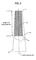
- the blade 10 includes a length L of honeycomb skin 23 that extends from about the tip 11 to some point along the body 13 of the blade 10.
- the length L may extend from about the tip 11 to about the root 12.
- the length, L starts at some distance from the tip 11, extending at least one of toward the root 12 and to the root 12.
- the honeycomb skin 23 need not have a uniform terminal edge 61, shown in FIG. 6 as perpendicular to the airfoil stacking axis.
- the terminal edge 61 of the honeycomb skin 23 may be shaped, such as according to the airfoil design, as indicated by the dashed line.
- the blade 10 may be implemented as a rotating component in any one of an aircraft engine (gas turbine 1), power generation gas turbine 1 and steam turbine 1.
- the blade 10 may be implemented advantageously in the fan compressor forward stages and the low pressure turbine latter stages.
- the blade 10 may be implemented advantageously in the compressor forward stages and the turbine latter stages.
- the blade 10 could be implemented advantageously in the low pressure section where the rotating blades become very large.
- the teachings herein provide for a large annulus area blade that uses a light weight honeycomb skin 23 forming an airfoil bonded (i.e., attached) to the high strength support structure 21.
- the high strength support structure 21 includes a thin wall casting or forging with a wall thickness less than about 0.03 inches at the tip 11. In other embodiments, an overall reduction of weight for the blade 10 is about 50%.
Landscapes
- Engineering & Computer Science (AREA)
- Architecture (AREA)
- Mechanical Engineering (AREA)
- General Engineering & Computer Science (AREA)
- Turbine Rotor Nozzle Sealing (AREA)
- Structures Of Non-Positive Displacement Pumps (AREA)
Applications Claiming Priority (1)
| Application Number | Priority Date | Filing Date | Title |
|---|---|---|---|
| US12/259,599 US20100104446A1 (en) | 2008-10-28 | 2008-10-28 | Fabricated hybrid turbine blade |
Publications (1)
| Publication Number | Publication Date |
|---|---|
| EP2182168A1 true EP2182168A1 (fr) | 2010-05-05 |
Family
ID=41632091
Family Applications (1)
| Application Number | Title | Priority Date | Filing Date |
|---|---|---|---|
| EP09173888A Withdrawn EP2182168A1 (fr) | 2008-10-28 | 2009-10-23 | Aube de turbine hybride fabriquée |
Country Status (4)
| Country | Link |
|---|---|
| US (1) | US20100104446A1 (fr) |
| EP (1) | EP2182168A1 (fr) |
| JP (1) | JP2010106833A (fr) |
| CN (1) | CN101725372A (fr) |
Cited By (4)
| Publication number | Priority date | Publication date | Assignee | Title |
|---|---|---|---|---|
| EP3064708A1 (fr) * | 2015-03-05 | 2016-09-07 | Techspace Aero S.A. | Aube composite de compresseur de turbomachine axiale avec une feuille de renfort et turbomachine comprenant une telle aube |
| WO2017189208A1 (fr) * | 2016-04-27 | 2017-11-02 | Siemens Energy, Inc. | Aube de turbine à gaz à paroi de pointe ondulée |
| US10260352B2 (en) | 2013-08-01 | 2019-04-16 | Siemens Energy, Inc. | Gas turbine blade with corrugated tip wall |
| EP3896255A1 (fr) * | 2020-04-17 | 2021-10-20 | Raytheon Technologies Corporation | Aube multi-matériaux pour un moteur à turbine à gaz |
Families Citing this family (3)
| Publication number | Priority date | Publication date | Assignee | Title |
|---|---|---|---|---|
| CN105050753B (zh) | 2013-01-16 | 2018-01-09 | 通用电气公司 | 金属结构 |
| DE102015203868A1 (de) * | 2015-03-04 | 2016-09-08 | Rolls-Royce Deutschland Ltd & Co Kg | Fanschaufel für einen Flugantrieb |
| US11519333B2 (en) * | 2020-09-10 | 2022-12-06 | General Electric Company | Turbine engine with shockwave attenuation |
Citations (5)
| Publication number | Priority date | Publication date | Assignee | Title |
|---|---|---|---|---|
| US5725354A (en) * | 1996-11-22 | 1998-03-10 | General Electric Company | Forward swept fan blade |
| US5725355A (en) * | 1996-12-10 | 1998-03-10 | General Electric Company | Adhesive bonded fan blade |
| EP1596036A1 (fr) * | 2004-05-14 | 2005-11-16 | General Electric Company | Aubes creuses soudées par friction-malaxage et procédé associé |
| US20070065291A1 (en) | 2005-09-16 | 2007-03-22 | General Electric Company | Hybrid blisk |
| EP1876324A2 (fr) * | 2006-07-06 | 2008-01-09 | Rolls-Royce Plc | Aube d'une turbine à gaz |
Family Cites Families (15)
| Publication number | Priority date | Publication date | Assignee | Title |
|---|---|---|---|---|
| US1992338A (en) * | 1931-06-05 | 1935-02-26 | Bendix Aviat Corp | Propeller blade and method of making the same |
| US2939944A (en) * | 1957-03-18 | 1960-06-07 | Budd Co | Method of fabricating honeycomb grid reinforced structure |
| US3217807A (en) * | 1964-08-28 | 1965-11-16 | Bell Aerospace Corp | Rotor blade |
| GB1214858A (en) * | 1968-05-20 | 1970-12-09 | Westland Aircraft Ltd | Improvements in or relating to the construction of rotor blades for rotary wing aircraft |
| US3644059A (en) * | 1970-06-05 | 1972-02-22 | John K Bryan | Cooled airfoil |
| US3782856A (en) * | 1972-05-31 | 1974-01-01 | United Aircraft Corp | Composite aerodynamic blade with twin-beam spar |
| US4084366A (en) * | 1975-11-14 | 1978-04-18 | Haworth Mfg., Inc. | Sound absorbing panel |
| US4382106A (en) * | 1981-09-08 | 1983-05-03 | International Honeycomb Corporation | Honeycomb panel with conformable surface |
| FR2602739B1 (fr) * | 1986-07-28 | 1988-11-18 | Aerospatiale | Pale en materiaux composites, a structure bilongeron et bicaisson, et a revetement stratifies a sandwich de nid d'abeilles, et son procede de fabrication |
| FR2746703B1 (fr) * | 1996-03-27 | 1998-04-24 | Cardo Door France | Procede et machine de fabrication de panneaux |
| US6372322B1 (en) * | 1998-05-28 | 2002-04-16 | Pactiv Corporation | Shaped honeycomb structures and method and apparatus for making shaped honeycomb structures |
| JP4086415B2 (ja) * | 1999-06-03 | 2008-05-14 | 株式会社荏原製作所 | タービン装置 |
| US6607358B2 (en) * | 2002-01-08 | 2003-08-19 | General Electric Company | Multi-component hybrid turbine blade |
| US8297027B2 (en) * | 2008-03-28 | 2012-10-30 | The United States Of America As Represented By The Secretary Of Agriculture | Engineered molded fiberboard panels and methods of making and using the same |
| US8366057B2 (en) * | 2009-07-28 | 2013-02-05 | University Of Kansas | Method and apparatus for pressure adaptive morphing structure |
-
2008
- 2008-10-28 US US12/259,599 patent/US20100104446A1/en not_active Abandoned
-
2009
- 2009-10-23 EP EP09173888A patent/EP2182168A1/fr not_active Withdrawn
- 2009-10-26 JP JP2009245093A patent/JP2010106833A/ja active Pending
- 2009-10-28 CN CN200910207871A patent/CN101725372A/zh active Pending
Patent Citations (5)
| Publication number | Priority date | Publication date | Assignee | Title |
|---|---|---|---|---|
| US5725354A (en) * | 1996-11-22 | 1998-03-10 | General Electric Company | Forward swept fan blade |
| US5725355A (en) * | 1996-12-10 | 1998-03-10 | General Electric Company | Adhesive bonded fan blade |
| EP1596036A1 (fr) * | 2004-05-14 | 2005-11-16 | General Electric Company | Aubes creuses soudées par friction-malaxage et procédé associé |
| US20070065291A1 (en) | 2005-09-16 | 2007-03-22 | General Electric Company | Hybrid blisk |
| EP1876324A2 (fr) * | 2006-07-06 | 2008-01-09 | Rolls-Royce Plc | Aube d'une turbine à gaz |
Cited By (7)
| Publication number | Priority date | Publication date | Assignee | Title |
|---|---|---|---|---|
| US10260352B2 (en) | 2013-08-01 | 2019-04-16 | Siemens Energy, Inc. | Gas turbine blade with corrugated tip wall |
| EP3064708A1 (fr) * | 2015-03-05 | 2016-09-07 | Techspace Aero S.A. | Aube composite de compresseur de turbomachine axiale avec une feuille de renfort et turbomachine comprenant une telle aube |
| BE1022809B1 (fr) * | 2015-03-05 | 2016-09-13 | Techspace Aero S.A. | Aube composite de compresseur de turbomachine axiale |
| US10280758B2 (en) | 2015-03-05 | 2019-05-07 | Safran Aero Boosters Sa | Composite compressor blade for an axial-flow turbomachine |
| WO2017189208A1 (fr) * | 2016-04-27 | 2017-11-02 | Siemens Energy, Inc. | Aube de turbine à gaz à paroi de pointe ondulée |
| EP3896255A1 (fr) * | 2020-04-17 | 2021-10-20 | Raytheon Technologies Corporation | Aube multi-matériaux pour un moteur à turbine à gaz |
| EP4353953A3 (fr) * | 2020-04-17 | 2024-06-12 | RTX Corporation | Aube en plusieurs matériaux pour un moteur à turbine à gaz |
Also Published As
| Publication number | Publication date |
|---|---|
| JP2010106833A (ja) | 2010-05-13 |
| US20100104446A1 (en) | 2010-04-29 |
| CN101725372A (zh) | 2010-06-09 |
Similar Documents
| Publication | Publication Date | Title |
|---|---|---|
| US6190133B1 (en) | High stiffness airoil and method of manufacture | |
| EP2182168A1 (fr) | Aube de turbine hybride fabriquée | |
| EP1887187B1 (fr) | Aube de rotor | |
| EP1980714B1 (fr) | Aube rotorique et turbine associée | |
| JP5550812B2 (ja) | タービンブレード装置 | |
| EP2348192B1 (fr) | Gaine d'aube de soufflante | |
| US7156622B2 (en) | Compressor blade for an aircraft engine | |
| US6524074B2 (en) | Gas turbine engine blade | |
| JP6692609B2 (ja) | タービンバケット組立体及びタービンシステム | |
| US10502064B2 (en) | Power beam welded cavity-back titanium hollow fan blade | |
| US20120021243A1 (en) | Components with bonded edges | |
| EP0924381A2 (fr) | Aube de turbomachine amortie en vibration | |
| US20130101423A1 (en) | Airfoil devices, leading edge components, and methods of making | |
| CN102947548A (zh) | 用于转子叶片的轻量围带翼片 | |
| US20060018761A1 (en) | Adaptable fluid flow device | |
| US7048507B2 (en) | Axial-flow thermal turbomachine | |
| US20150345314A1 (en) | Turbine bucket assembly and turbine system | |
| EP3617453B1 (fr) | Pale de soufflante dotée d'une gaine métallique fermée | |
| US7419363B2 (en) | Turbine blade with ceramic tip | |
| US20240376825A1 (en) | Flow body for a gas turbine, gas turbine, method for manufacturing a flow body for a gas turbine, and method for repairing a flow body of a gas turbine | |
| JP2015224635A (ja) | タービンバケット組立体及びタービンシステム | |
| US20240376826A1 (en) | Flow body for a gas turbine, gas turbine, method for manufacturing a flow body for a gas turbine, and method for repairing a flow body of a gas turbine | |
| EP3460188A1 (fr) | Composant de surface portante et procédé |
Legal Events
| Date | Code | Title | Description |
|---|---|---|---|
| PUAI | Public reference made under article 153(3) epc to a published international application that has entered the european phase |
Free format text: ORIGINAL CODE: 0009012 |
|
| AK | Designated contracting states |
Kind code of ref document: A1 Designated state(s): AT BE BG CH CY CZ DE DK EE ES FI FR GB GR HR HU IE IS IT LI LT LU LV MC MK MT NL NO PL PT RO SE SI SK SM TR |
|
| AX | Request for extension of the european patent |
Extension state: AL BA RS |
|
| 17P | Request for examination filed |
Effective date: 20101105 |
|
| 17Q | First examination report despatched |
Effective date: 20101207 |
|
| STAA | Information on the status of an ep patent application or granted ep patent |
Free format text: STATUS: THE APPLICATION IS DEEMED TO BE WITHDRAWN |
|
| 18D | Application deemed to be withdrawn |
Effective date: 20140501 |