EP1596202B1 - Méthode et système d'équilibrage d'un objet tournant - Google Patents
Méthode et système d'équilibrage d'un objet tournant Download PDFInfo
- Publication number
- EP1596202B1 EP1596202B1 EP05103857A EP05103857A EP1596202B1 EP 1596202 B1 EP1596202 B1 EP 1596202B1 EP 05103857 A EP05103857 A EP 05103857A EP 05103857 A EP05103857 A EP 05103857A EP 1596202 B1 EP1596202 B1 EP 1596202B1
- Authority
- EP
- European Patent Office
- Prior art keywords
- rotation
- article
- angle
- determining
- magnetic
- Prior art date
- Legal status (The legal status is an assumption and is not a legal conclusion. Google has not performed a legal analysis and makes no representation as to the accuracy of the status listed.)
- Expired - Lifetime
Links
Images


Classifications
-
- G—PHYSICS
- G01—MEASURING; TESTING
- G01P—MEASURING LINEAR OR ANGULAR SPEED, ACCELERATION, DECELERATION, OR SHOCK; INDICATING PRESENCE, ABSENCE, OR DIRECTION, OF MOVEMENT
- G01P3/00—Measuring linear or angular speed; Measuring differences of linear or angular speeds
- G01P3/42—Devices characterised by the use of electric or magnetic means
- G01P3/44—Devices characterised by the use of electric or magnetic means for measuring angular speed
- G01P3/48—Devices characterised by the use of electric or magnetic means for measuring angular speed by measuring frequency of generated current or voltage
- G01P3/481—Devices characterised by the use of electric or magnetic means for measuring angular speed by measuring frequency of generated current or voltage of pulse signals
- G01P3/487—Devices characterised by the use of electric or magnetic means for measuring angular speed by measuring frequency of generated current or voltage of pulse signals delivered by rotating magnets
-
- G—PHYSICS
- G01—MEASURING; TESTING
- G01D—MEASURING NOT SPECIALLY ADAPTED FOR A SPECIFIC VARIABLE; ARRANGEMENTS FOR MEASURING TWO OR MORE VARIABLES NOT COVERED IN A SINGLE OTHER SUBCLASS; TARIFF METERING APPARATUS; MEASURING OR TESTING NOT OTHERWISE PROVIDED FOR
- G01D2205/00—Indexing scheme relating to details of means for transferring or converting the output of a sensing member
- G01D2205/80—Manufacturing details of magnetic targets for magnetic encoders
Definitions
- the invention relates to a balancing method in which a magnetic mark is attached to a rotatable object to be positioned for determining rotational angles, rotational speeds or rotational behavior, and a balancing system with a device for mounting magnetic marks and a device for determining the angle of rotation.
- the mark denotes an object-fixed angular reference system. Such methods and devices are used to balance objects.
- the object is also called rotor.
- Such marks may be optical, magnetic or mechanical in nature.
- a color mark is attached to the rotor, which can be detected optically.
- An optical mark is not applicable in cases where the rotor is mounted in an optically opaque or optical pathway environment.
- Magnetic marks are usually small permanent magnets used, which are attached to the rotor. However, this leads to a change in the mass distribution on the rotor and influences the balancing of the rotor.
- a method for generating rectangular voltages for measuring and evaluation of balancing machines is known in which a mark of a rotor is scanned photoelectrically or electromagnetically. From the needle-pulse-shaped scanning voltages, two square-wave voltages which are phase-shifted by 90 ° relative to one another are derived, which are of an exact rectangular shape and whose shape is independent of the frequency of the needle pulses.
- a method for producing localized magnetizations for example for encoding purposes in information carriers, magnetic keys, magnetic identification devices and the like, as well as a corresponding device, is known.
- the method described in this document involves placing, at the point to be magnetized, a narrow radius hairpin-shaped loop of the conductor at a substantially right angle with its tip on the surface of the body of magnetizable material and applying it to the magnetizing current magnetic dipole with very small pole distance is generated in a near-surface layer of the body.
- a high information density is achieved in the body.
- the document makes no reference to methods and apparatus for attaching magnetic marks to a rotatable article to be positioned for determining angles of rotation.
- a method with the features of the preamble of claim 1 is known.
- a ferromagnetic circumferential track of a body to be balanced is first demagnetized or magnetically homogenized and then generated at a location in the vicinity of the circulating track by means of a short-time magnetic pulse of high intensity a locally limited magnetization to form a reference mark.
- the method has the disadvantage that with the aid of the reference mark located on a circumferential track, the angular position of an imbalance can not be detected directly, but that additionally a rotational angle measuring device scanning the reference mark is required.
- a system comprising a device for generating a magnetic reference mark is known with an electromagnet, which is connected via a controlled switch to a powered by a DC storage capacitor.
- the system has a scanner for scanning the circumferential track and the fiducial.
- GB 2 169 712 A there is described a method and apparatus for obtaining a repeating signal from a rotating wave, the repetition rate of the signal being proportional to the rotational speed of the wave.
- an electromagnetic probe is disposed at a distance close to the rotating shaft and is excited for a predetermined interval at a repetition rate equal to a multiple of the shaft rotation speed to record discrete magnetization areas, the number of which depends on the shaft rotation speed, on the shaft surface. Thereafter, the probe is no longer energized and used as a sensor to sample playback pulses generated by the magnetized portion of the rotating shaft.
- the repetition rate of the playback pulses is a measure of the instantaneous angular velocity of the shaft. A rotation angle measurement is not possible with this device.
- JP 01189517 A discloses a device for measuring a rotational movement of a rotor coupled to a rotatable magnetic spindle.
- a circular magnetic pattern is formed concentrically with the axis of rotation of the spindle.
- a magnetic sensor from the signal size and direction of the rotational movement of the spindle is calculated.
- a measured angular orientation is dependent on the initial position at the beginning of the measuring process, so that upon removal of the spindle from the measuring device, angle-related measurement results are lost.
- JP 04 337401 A an apparatus for recording magnetic signals in a magnetic layer formed on the peripheral surface of a rotatable shaft is known.
- a detector detects the beginning of the magnetic recording just before a full shaft revolution is reached.
- JP 63 182808 A An apparatus for producing small circular magnetic encoder disks of sufficient flux density is made JP 63 182808 A known.
- a current-carrying conductor loop is provided for magnetization, which has substantially the shape of a horizontal eight. This results in the magnetization of a single dipole.
- the invention has for its object to provide a method of the type specified, which allows a non-contact determination of the rotation angle of the rotating object to be positioned in different environments and at the same time avoids the problems of a mass tag. Likewise, problems of mechanically coupled devices for determining angles of rotation, for example associated with slippage by belt drives, should be avoided.
- the balancing method according to the invention and the balancing system according to the invention thus advantageously make use of the property of rotatable objects (rotors) to be positioned, made of readily magnetizable material, for example ferromagnetic material.
- a region of the rotating object to be positioned and itself becomes a mark, which can be used to determine angles of rotation.
- a mass change of the rotor does not occur.
- the mark can also be detected by the system according to the invention in an advantageous manner without contact and allows the position of the dipole, the determination of the rotational angle of the rotor to position the rotor for balancing.
- the acquisition of further measured values is not required.
- the problems associated with slippage by belt drives or other mechanical devices for determining the angle of rotation can therefore be advantageously avoided by the method and apparatus of the invention.
- An embodiment of the device according to the invention which is advantageous for the detection of the magnetic marks consists in that the conductor loop through which the current flows is arranged in its end closest to the rotating object to be positioned in a plane which runs essentially perpendicular to the axis of rotation of the object.
- the inventive device can be realized easily and inexpensively, when the current-carrying conductor loop is arranged in a substantially parallel to a plate surface plane extending groove of a ceramic plate, wherein the ceramic plate is disposed on the rotatable object to be positioned opposite end face of the device and in Substantially perpendicular to the axis of rotation of the article.
- the device for applying a magnetic mark further comprises a control device which controls the pulse duration and the pulse shape and the current strength of the current pulse flowing through the conductor for generating the magnetic field and is connected to the conductor loop.
- the current pulse which flows through the conductor loop and generates the magnetic mark in the rotor can be influenced in such a way that, in accordance with the respective rotor shape, a mark which is optimal for determining the rotational angle in shape and magnetic field strength is generated.
- the current-carrying conductor loop can be used in addition to the removal of the mark after completion of the balancing process.
- possibly occurring negative effects of the magnetized rotor are avoided in the intended use of the rotor.
- the development of the device according to the invention offers for this purpose a very simple possibility.
- the control device advantageously generates the electrical alternating currents of the required amplitude and frequency necessary for eliminating the mark.
- the system according to the invention of the device for applying magnetic marks and the device for determining the angle of rotation advantageously has two mutually offset magnetic field sensors, from whose signals a signal processing device determines the current angle of rotation of the rotatable object to be positioned.
- the signals which are generated by the magnetic field sensors and are dependent on the position of the mark, permit the direct determination of the current rotational angle when the magnetic field sensors are arranged offset by an angle of rotation of 90 ° relative to one another.
- the magnetic field sensors then generate sine and cosine functions which lead to the angle of rotation via the function of the arctan (arctan).
- a further advantageous use of the system according to the invention can be made if the device for determining the rotation angle additionally has a rotational speed determination device.
- abrasion-resistant ceramic materials are advantageously used on the end face of the respective device.
- the manual alignment of the apparatus for determining the angle of rotation is advantageous by the Anbrin Positioning removal of masses to eliminate the imbalance, the inventive system cooperates with a device which rotates the object to be balanced.
- the system may be modular in that the apparatus for attaching a magnetic tag is made detachable.
- FIG. 1 is the object to be balanced 1, also called rotor shown.
- the rotor 1 is in an in FIG. 1 not shown bracket or a balancing machine stored.
- the system 2 according to the invention is arranged from a device for applying a magnetic mark and the device for determining the angle of rotation 25.
- the device for attaching a magnetic mark consists of a ceramic plate 21 with not shown, current-carrying conductor loop and a control device 23.
- the arranged on or within the ceramic plate 21, current-carrying conductor loop is electrically connected to the control device 23, which is used to control the flowing through the conductor loop Current pulse with the parameters current, pulse shape and duration is used.
- this face 12 must consist of magnetizable material, in particular a ferromagnetic material such as iron, nickel, cobalt or a so-called Heusler alloy.
- the end face 12 of the rotor 1 is used to determine the angle of rotation and the magnetization introduced into this end face serves as a magnetic mark for determining this angle of rotation. This mark may also serve to rotate the rotor to a position with a predetermined angle of rotation.
- FIG. 1 also shows that the device for determining the angle of rotation 25 on its face facing the rotor 1 has ceramic material 252 in the form of a ceramic plate.
- the inventive system 2 is in FIG. 2 once again illustrated in an exploded view. It can be seen that the system 2 is of modular design, so that, if necessary, the device 23, 21 for attaching a magnetic mark without the device 25 for determining the angle of rotation can be used to apply only the magnetic mark on the end face 12 of the rotor 1 , In order to establish an electrical connection between the control device 23 and the current-carrying conductor loop of the ceramic plate 21, connections 232 are provided on the control device 23 and are inserted into recesses (not shown) of the ceramic plate 21.
- the former Since the device for determining the angle of rotation 25 can be used independently of the device 23, 21 for attaching the magnetic mark, the former has a face 252 made of ceramic material, which is resistant to abrasion and mechanical damage to the device for determining the angle of rotation 25 through the Rotor 1 minimized.
- the ceramic plate 21 has the function of preventing the destruction of the device for attaching a magnetic mark 21, 23 and in addition to isolating the current-carrying conductor loop from the environment.
- the ceramic plate 21 has a groove 211, in which in a first embodiment, the current-carrying conductor loop is realized in the form of a wire along the groove.
- the current-carrying conductor loop runs in this case along a straight line which is perpendicular to the axis of rotation 3 of the rotor 1.
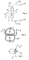
- FIG. 3 Such a conductor loop is in FIG. 3 shown schematically.
- the current-carrying conductor 212 with a current direction 5 generates around this conductor loop a magnetic field whose field line profile is illustrated by means of the circular line 7 with an arrow.
- the direction of the magnetic field generated by a current-carrying conductor is described by the Biot-Savartsche law.
- the polarity of the magnetic field is in FIG. 3 illustrated by the letters "N" and "S" for north and south.
- the current-carrying conductor 212 is connected by means of the connecting lines 214 and the terminals 216 via in the Figures 1 and 2 shown control device 23 connected to the power supply.
- FIG. 4 a further embodiment of a current-carrying conductor.
- the current-carrying conductor 217 has the shape of a horizontal eight, wherein the power supply and current discharge takes place respectively at the center line of the lying eight and the current passes through the two circular parts of the lying eight in different directions (clockwise and counterclockwise). Accordingly, magnetic poles of different polarity are generated in the interiors of the two circular parts of the lying eight, which are represented by the letters "S" and "N".
- the current-carrying conductors 212 and 217 may be embedded in the ceramic plate 21 or at least partially disposed on the surface of this ceramic plate 21. For this purpose, the ceramic plate 21 may have a correspondingly shaped recess or groove.
- the ceramic plate 21 accommodating the current-carrying conductors 212 and 217 can be selected in a preferred exemplary embodiment from a set having different plate sizes assigned to respective rotor diameter ranges.
- FIG. 5 shows the magnetic mark on the end surface 12 of the axis of the rotor 1.
- the position of the magnetic mark can be determined by a contactless sensor technique, which is arranged in the device for determining the angle of rotation 25.
- the magnetic marker can be generated analogously to the method explained above by means of a permanent magnet instead of a current-carrying conductor.
- a current-carrying Head higher and variable magnetic field strength is achievable, this method is preferred in the application.
- FIG. 6 shows the device for determining the angle of rotation 25 in an exploded view with the ceramic plate 252 and the signal receiving and processing means 254.
- the ceramic plate 252 is disposed in front of the rotor side of the signal receiving and processing device 254 and has a range of color-changed ceramic Material 253 on.
- the borderline between the areas of different color lies on the centerline and is a visible marker. It is used for manual alignment of the device relative to the rotor.
- the magnetic field sensors 256 and 257 are arranged along the center lines 8 and 9 of the rotor-facing end face of the signal receiving and processing device 254, the first magnetic field sensor 256 being offset from the second magnetic field sensor 257 by 90 °.
- the magnetic field sensors are preferably magnetoresistive sensors with high sensitivity. In a further embodiment, the magnetic field sensors can also be designed as Hall sensors.
- the magnetic field sensors 256 and 257 are connected to the signal processing device 259 via connection lines 258.
- the analog sine and cosine signals generated by the displacement of the magnetic field sensors 256 and 257 by 90 ° are first amplified by the signal processing device 259 in an amplifier and equalization stage. Subsequently, a known interpolation ASIC digital incremental signals are generated, which directly represent the current rotation angle of the rotor.
- the interpolation ASIC automatically corrects offset, amplitude or phase shift between the sine and cosine signals within small limits.
- a rough parameterization or calibration can be performed by a calibration and parameterizing device 13, for example a laptop, which is connected via a connecting line 10 to the signal processing device 259.
- the signal processing device 259 is further connected via a connecting line 10 to a device for rotating the object to be balanced 11.
- the object to be balanced can be moved controlled by the device for determining the angle of rotation 25 in a position with a certain angle of rotation. In such a position, by adding or removing mass to the rotor 1, it can be balanced.
- the speed of the rotor 1 can be determined by means of the signal processing device 259 from the sine and cosine signals obtained from the magnetic field sensors 256 and 257.
- the rotational behavior can be detected.
Landscapes
- Physics & Mathematics (AREA)
- General Physics & Mathematics (AREA)
- Measurement Of Length, Angles, Or The Like Using Electric Or Magnetic Means (AREA)
- Transmission And Conversion Of Sensor Element Output (AREA)
- Golf Clubs (AREA)
- Dynamo-Electric Clutches, Dynamo-Electric Brakes (AREA)
Claims (16)
- Procédé d'équilibrage, dans lequel, pour déterminer les angles de rotation, les vitesses de rotation ou le comportement de rotation d'un objet rotatif autour d'un axe et devant être positionné pour l'équilibrage, un dipôle magnétique est généré par un champ magnétique sous la forme d'un repère magnétique dans une zone de l'objet appropriée à la détermination de l'angle de rotation et réalisée dans un matériau magnétisable, l'angle de rotation de la position d'équilibrage étant déterminé au moyen de ce repère, caractérisé en ce qu'un dispositif pour générer un champ magnétique est disposé sur une face frontale de l'objet rotatif, et dans la zone de la face frontale, proche de la surface, un seul dipôle magnétique est généré dont les pôles sont disposés selon une symétrie de révolution par rapport à l'axe de rotation de l'objet.
- Procédé selon la revendication 1, caractérisé en ce que le champ magnétique est généré par une boucle conductrice traversée par un courant.
- Système d'équilibrage, comportant un dispositif pour appliquer un repère magnétique afin de déterminer les angles de rotation sur un objet (1) rotatif devant être positionné pour l'équilibrage, le dispositif comportant des moyens pour générer un dipôle magnétique dans une zone (12) magnétisable de l'objet (1) rotatif prévue pour la détermination de l'angle de rotation, et comportant un dispositif pour déterminer l'angle de rotation (25) et un dispositif premettant de faire tourner l'objet dans la position d'équilibrage, caractérisé en ce que le dispositif pour appliquer un repère magnétique est réalisé pour générer sur une face frontale de l'objet rotatif un dipôle magnétique présentant une symétrie de révolution par rapport à l'axe de rotation de l'objet (1) rotatif, et est disposé, selon une observation depuis l'objet (1) rotatif dans la direction de l'axe de rotation (3), devant le dispositif pour déterminer l'angle de rotation (25).
- Système selon la revendication 3, caractérisé en ce qu'une boucle conductrice traversée par un courant est utilisée comme moyens pour générer un champ magnétique.
- Système selon la revendication 4, caractérisé ce que la boucle conductrice traversée par un courant, dans son extrémité située au plus près de l'objet (1) rotatif à positionner, est disposée dans un plan sensiblement perpendiculaire à l'axe de rotation (3) de l'objet.
- Système selon la revendication 4 ou 5, caractérisé en ce que la boucle conductrice traversée par un courant est disposée dans une rainure (211) d'une plaque en céramique (21), ladite rainure étant sensiblement parallèle à un plan de la surface de la plaque, ladite plaque en céramique (21) étant disposée sur la face frontale du dispositif, située en face de l'objet et s'étendant sensiblement perpendiculairement à l'axe de rotation (3) de l'objet rotatif à positionner.
- Système selon la revendication 5 ou 6, caractérisé en ce que la boucle conductrice traversée par un courant épouse sensiblement la forme d'un huit couché.
- Système selon l'une quelconque des revendications 4 à 7, caractérisé en ce que le dispositif comporte un dispositif de commande (23) qui commande la durée d'impulsion et la forme de l'impulsion, ainsi que l'intensité du courant de l'impulsion de courant traversant la boucle pour générer le champ magnétique et qui est relié à la boucle conductrice.
- Système selon l'une des revendications 4 à 8, caractérisé en ce que le dispositif de commande (23) est conçu de telle sorte que des courants électriques alternatifs nécessaires pour éliminer le repère magnétique peuvent être générés avec l'amplitude et la fréquence nécessaires.
- Système selon l'une des revendications 3 à 9, caractérisé en ce que le dispositif pour déterminer l'angle de rotation (25) comporte deux capteurs de champ magnétique (256, 257) situés à distance d'un axe de mesure correspondant à l'axe de rotation (3) de l'objet (1) rotatif et qui sont décalés l'un par rapport à l'autre dans le sens de rotation par rapport à l'axe de mesure, à partir des signaux desquels un dispositif de traitement de signaux (254) détermine l'angle de rotation actuel de l'objet (1) rotatif à positionner.
- Système selon la revendication 10, caractérisé en ce que les deux capteurs de champ magnétique (256, 257) sont décalés l'un par rapport à l'autre par rapport à l'axe de mesure d'un angle de rotation de 90°.
- Système selon l'une des revendications 3 à 11, caractérisé en ce que le dispositif pour déterminer l'angle de rotation (25) comporte, en plus, des moyens pour déterminer la vitesse de rotation.
- Système selon l'une des revendications 3 à 12, caractérisé en ce que la face frontale du dispositif pour déterminer l'angle de rotation (25) qui est orientée vers l'objet (1) est réalisée dans un matériau céramique.
- Système selon l'une des revendications 3 à 13, caractérisé en ce que la face frontale du dispositif pour déterminer l'angle de rotation (25) qui est orientée vers l'objet (1) comporte un repère visible pour l'orientation manuelle de ce dispositif.
- Système selon l'une des revendications 3 à 14, caractérisé par un dispositif à l'aide duquel l'objet (1) peut être tourné dans un angle de rotation prédéfini.
- Système selon l'une des revendications 3 à 15, caractérisé en ce que le dispositif pour appliquer un repère magnétique est amovible.
Priority Applications (1)
| Application Number | Priority Date | Filing Date | Title |
|---|---|---|---|
| PL05103857T PL1596202T4 (pl) | 2004-05-14 | 2005-05-10 | Sposób i system wyważania obrotowego przedmiotu |
Applications Claiming Priority (2)
| Application Number | Priority Date | Filing Date | Title |
|---|---|---|---|
| DE102004024406 | 2004-05-14 | ||
| DE102004024406A DE102004024406A1 (de) | 2004-05-14 | 2004-05-14 | Verfahren zum Anbringen einer magnetischen Marke an einem zu positionierenden drehbaren Gegenstand und entsprechende Vorrichtung |
Publications (2)
| Publication Number | Publication Date |
|---|---|
| EP1596202A1 EP1596202A1 (fr) | 2005-11-16 |
| EP1596202B1 true EP1596202B1 (fr) | 2008-11-05 |
Family
ID=34939755
Family Applications (1)
| Application Number | Title | Priority Date | Filing Date |
|---|---|---|---|
| EP05103857A Expired - Lifetime EP1596202B1 (fr) | 2004-05-14 | 2005-05-10 | Méthode et système d'équilibrage d'un objet tournant |
Country Status (6)
| Country | Link |
|---|---|
| US (1) | US7505242B2 (fr) |
| EP (1) | EP1596202B1 (fr) |
| AT (1) | ATE413604T1 (fr) |
| DE (2) | DE102004024406A1 (fr) |
| ES (1) | ES2317144T3 (fr) |
| PL (1) | PL1596202T4 (fr) |
Families Citing this family (7)
| Publication number | Priority date | Publication date | Assignee | Title |
|---|---|---|---|---|
| DE102006036010A1 (de) * | 2006-08-02 | 2008-02-07 | Schaeffler Kg | Radsatzlagereinheit mit Drehzahlmesseinrichtung und Sensoranordnung hierfür |
| US9010461B2 (en) | 2009-06-01 | 2015-04-21 | Halliburton Energy Services, Inc. | Guide wire for ranging and subsurface broadcast telemetry |
| WO2011002461A1 (fr) | 2009-07-02 | 2011-01-06 | Halliburton Energy Services, Inc. | Réseau de forage pour la mesure de distances et la télémétrie en puits croisés |
| DE102009054575B4 (de) * | 2009-12-11 | 2020-03-12 | Aip Gmbh & Co. Kg | Stellvorrichtung für einen Fahrroboter |
| US9581718B2 (en) * | 2010-03-31 | 2017-02-28 | Halliburton Energy Services, Inc. | Systems and methods for ranging while drilling |
| EP2463664A1 (fr) | 2010-12-09 | 2012-06-13 | Turner Powertrain Systems Limited | Mesure de la vitesse, de déplacement, de la position ou du mouvement angulaires d'arbre |
| US11353337B2 (en) * | 2020-11-03 | 2022-06-07 | Semiconductor Components Industries, Llc | Offset cancel systems and methods for resolver-type sensors |
Family Cites Families (14)
| Publication number | Priority date | Publication date | Assignee | Title |
|---|---|---|---|---|
| DE1103637B (de) | 1958-11-26 | 1961-03-30 | Hofmann K G Maschinenfabrik | Verfahren und Einrichtung zur Erzeugung von Rechteckspannungen fuer Mess- und Auswerteeinrichtungen von Auswuchtmaschinen |
| US3555464A (en) * | 1969-08-07 | 1971-01-12 | Tdk Electronics Co Ltd | Compact lcr component and method of making |
| US4064704A (en) * | 1975-12-05 | 1977-12-27 | Ird Mechanalysis, Inc. | Vibration analyzing apparatus |
| DE2558159B2 (de) | 1975-12-23 | 1978-06-15 | Mrt Magnet-Regeltechnik Gmbh, 2000 Hamburg | Verfahren zum Herstellen von örtlichen Magnetisierungen in Körpern aus magnetisierbarem Werkstoff und mit Hilfe des Verfahrens hergestellter Magnetkörper, insbesondere Codeträger |
| DE2839819A1 (de) * | 1978-09-13 | 1980-03-27 | Reutlinger Wolf Dieter | Verfahren und vorrichtung zum aufbringen einer abtastbaren bezugsmarke auf einen auszuwuchtenden koerper |
| DE3600306A1 (de) * | 1985-01-11 | 1986-08-21 | General Electric Co., Schenectady, N.Y. | Verfahren und einrichtung zum erzeugen von winkelgeschwindigkeitssignalen durch magnetische aufzeichnung und wiedergabe |
| JPS63182808A (ja) * | 1987-01-23 | 1988-07-28 | Yaskawa Electric Mfg Co Ltd | 磁気エンコ−ダ用磁石の製造方法 |
| JPH01189517A (ja) * | 1988-01-26 | 1989-07-28 | Yamaha Corp | 磁気エンコーダ |
| JP2589786B2 (ja) * | 1988-10-18 | 1997-03-12 | 松下電器産業株式会社 | 磁気センサー |
| JPH04337401A (ja) * | 1991-05-14 | 1992-11-25 | Mazda Motor Corp | 磁気記録体への着磁方法及びその装置 |
| DE19646251C2 (de) * | 1996-11-08 | 1998-11-12 | Continental Ag | Luftreifen mit Mitteln zur Beschaffung von Informationen, seine Verwendung und Vorrichtung zu seiner Herstellung |
| DE19733885A1 (de) * | 1997-08-05 | 1999-02-11 | Horst Nahr Ges Fuer Elektronis | Verfahren zum Messen von Wegen und Drehwinkeln an bewegten Gegenständen mit einer hartmagnetischen Oberfläche und Vorrichtung zur Durchführung des Verfahrens |
| US6584838B2 (en) * | 2001-01-11 | 2003-07-01 | Sensor Solutions Corporation | Angular position sensor |
| US6954685B2 (en) * | 2002-04-23 | 2005-10-11 | Lord Corporation | Aircraft vehicular propulsion system monitoring device and method |
-
2004
- 2004-05-14 DE DE102004024406A patent/DE102004024406A1/de not_active Withdrawn
-
2005
- 2005-05-10 DE DE502005005851T patent/DE502005005851D1/de not_active Expired - Lifetime
- 2005-05-10 ES ES05103857T patent/ES2317144T3/es not_active Expired - Lifetime
- 2005-05-10 PL PL05103857T patent/PL1596202T4/pl unknown
- 2005-05-10 AT AT05103857T patent/ATE413604T1/de not_active IP Right Cessation
- 2005-05-10 EP EP05103857A patent/EP1596202B1/fr not_active Expired - Lifetime
- 2005-05-13 US US11/128,745 patent/US7505242B2/en not_active Expired - Fee Related
Also Published As
| Publication number | Publication date |
|---|---|
| PL1596202T4 (pl) | 2017-03-31 |
| US20050259377A1 (en) | 2005-11-24 |
| EP1596202A1 (fr) | 2005-11-16 |
| US7505242B2 (en) | 2009-03-17 |
| ES2317144T3 (es) | 2009-04-16 |
| ATE413604T1 (de) | 2008-11-15 |
| PL1596202T3 (pl) | 2009-04-30 |
| DE102004024406A1 (de) | 2005-12-08 |
| DE502005005851D1 (de) | 2008-12-18 |
Similar Documents
| Publication | Publication Date | Title |
|---|---|---|
| DE69927385T2 (de) | Bürstenloser elektrischer Motor mit zwei senkrechten Hall Wandlern | |
| DE69938221T2 (de) | Positionssensor | |
| EP3325979B1 (fr) | Procédé et dispositif de fonctionnement d'un capteur de vitesse de rotation, système de capteurs de vitesse de rotation | |
| EP2596318B1 (fr) | Détermination de l'accouplement de pièces à une machine | |
| EP0736183A1 (fr) | Dispositif de detection de mouvements rotatifs et angulaires | |
| DE112005001382B4 (de) | Magnetische Codiereinheit | |
| EP1556665B1 (fr) | Tete de sonde a aimant et element a effet hall a utiliser dans un appareil de mesure de coordonnees | |
| EP1510787B1 (fr) | Procédé et capteur angulaire de mesure de la position angulaire absolue | |
| EP1596202B1 (fr) | Méthode et système d'équilibrage d'un objet tournant | |
| DE4435678A1 (de) | Magnetfeldsensor | |
| DE102017123772B4 (de) | Elektromagnetisches Messsystem für die Erfassung von Länge und Winkel basierend auf dem Magnetoimpedanzeffekt | |
| DE10012202C2 (de) | Einrichtung zur Erfassung von Geschwindigkeit, Bewegungsrichtung und/oder Position eines zu bewegenden Geräteteils | |
| DE3836508C2 (fr) | ||
| WO2016150616A1 (fr) | Ensemble de détection pour la détection de la vitesse de rotation d'un composant en rotation | |
| EP2339299A2 (fr) | Agencement de détection d'angle rotatif et procédé de détermination de la position rotative d'un arbre | |
| EP0266585A1 (fr) | Dispositif compte-tours, en particulier pour des dispositifs antiblocages de véhicules comprenant un capteur magnétorésistif | |
| DE19504307A1 (de) | Einrichtung zur Erfassung von Position und/oder Geschwindigkeit eines beweglichen Geräteteils | |
| DE10123539B4 (de) | Magnetische Längenmessvorrichtung | |
| EP3695194B1 (fr) | Système de mesure électromagnétique permettant de détecter une longueur ou un angle, sur la base de l'effet de magnéto-impédance | |
| DE102004020734A1 (de) | Winkelmeßsystem auf Magnetbasis mit hoher Meßgenauigkeit und Verfahren zur Bestimmung der Offset-Korrekturen bei einem solchen Winkelmeßsystem | |
| DE102005061347A1 (de) | Anordnung zur Messung des absoluten Drehwinkels einer Welle | |
| WO2019120688A1 (fr) | Dispositif de roue émettrice et procédé de détermination d'une position angulaire absolue et d'un sens de rotation | |
| DE102005025417B4 (de) | Lagegeber | |
| EP0548674B1 (fr) | Dispositif pour mesurer la distance des essieux entre les cylindres | |
| EP3557188B1 (fr) | Bielle magnétisée destinée à la mesure de course |
Legal Events
| Date | Code | Title | Description |
|---|---|---|---|
| PUAI | Public reference made under article 153(3) epc to a published international application that has entered the european phase |
Free format text: ORIGINAL CODE: 0009012 |
|
| AK | Designated contracting states |
Kind code of ref document: A1 Designated state(s): AT BE BG CH CY CZ DE DK EE ES FI FR GB GR HU IE IS IT LI LT LU MC NL PL PT RO SE SI SK TR |
|
| AX | Request for extension of the european patent |
Extension state: AL BA HR LV MK YU |
|
| 17P | Request for examination filed |
Effective date: 20060112 |
|
| AKX | Designation fees paid |
Designated state(s): AT BE BG CH CY CZ DE DK EE ES FI FR GB GR HU IE IS IT LI LT LU MC NL PL PT RO SE SI SK TR |
|
| GRAP | Despatch of communication of intention to grant a patent |
Free format text: ORIGINAL CODE: EPIDOSNIGR1 |
|
| RTI1 | Title (correction) |
Free format text: METHOD AND SYSTEM FOR BALANCING A ROTATABLE OBJECT |
|
| GRAS | Grant fee paid |
Free format text: ORIGINAL CODE: EPIDOSNIGR3 |
|
| GRAA | (expected) grant |
Free format text: ORIGINAL CODE: 0009210 |
|
| AK | Designated contracting states |
Kind code of ref document: B1 Designated state(s): AT BE BG CH CY CZ DE DK EE ES FI FR GB GR HU IE IS IT LI LT LU MC NL PL PT RO SE SI SK TR |
|
| REG | Reference to a national code |
Ref country code: GB Ref legal event code: FG4D Free format text: NOT ENGLISH |
|
| REG | Reference to a national code |
Ref country code: CH Ref legal event code: EP |
|
| REG | Reference to a national code |
Ref country code: IE Ref legal event code: FG4D Free format text: LANGUAGE OF EP DOCUMENT: GERMAN |
|
| REF | Corresponds to: |
Ref document number: 502005005851 Country of ref document: DE Date of ref document: 20081218 Kind code of ref document: P |
|
| NLV1 | Nl: lapsed or annulled due to failure to fulfill the requirements of art. 29p and 29m of the patents act | ||
| REG | Reference to a national code |
Ref country code: ES Ref legal event code: FG2A Ref document number: 2317144 Country of ref document: ES Kind code of ref document: T3 |
|
| LTIE | Lt: invalidation of european patent or patent extension |
Effective date: 20081105 |
|
| PG25 | Lapsed in a contracting state [announced via postgrant information from national office to epo] |
Ref country code: LT Free format text: LAPSE BECAUSE OF FAILURE TO SUBMIT A TRANSLATION OF THE DESCRIPTION OR TO PAY THE FEE WITHIN THE PRESCRIBED TIME-LIMIT Effective date: 20081105 |
|
| REG | Reference to a national code |
Ref country code: PL Ref legal event code: T3 |
|
| PG25 | Lapsed in a contracting state [announced via postgrant information from national office to epo] |
Ref country code: SI Free format text: LAPSE BECAUSE OF FAILURE TO SUBMIT A TRANSLATION OF THE DESCRIPTION OR TO PAY THE FEE WITHIN THE PRESCRIBED TIME-LIMIT Effective date: 20081105 Ref country code: FI Free format text: LAPSE BECAUSE OF FAILURE TO SUBMIT A TRANSLATION OF THE DESCRIPTION OR TO PAY THE FEE WITHIN THE PRESCRIBED TIME-LIMIT Effective date: 20081105 Ref country code: IS Free format text: LAPSE BECAUSE OF FAILURE TO SUBMIT A TRANSLATION OF THE DESCRIPTION OR TO PAY THE FEE WITHIN THE PRESCRIBED TIME-LIMIT Effective date: 20090305 Ref country code: NL Free format text: LAPSE BECAUSE OF FAILURE TO SUBMIT A TRANSLATION OF THE DESCRIPTION OR TO PAY THE FEE WITHIN THE PRESCRIBED TIME-LIMIT Effective date: 20081105 |
|
| REG | Reference to a national code |
Ref country code: IE Ref legal event code: FD4D |
|
| PG25 | Lapsed in a contracting state [announced via postgrant information from national office to epo] |
Ref country code: RO Free format text: LAPSE BECAUSE OF FAILURE TO SUBMIT A TRANSLATION OF THE DESCRIPTION OR TO PAY THE FEE WITHIN THE PRESCRIBED TIME-LIMIT Effective date: 20081105 Ref country code: DK Free format text: LAPSE BECAUSE OF FAILURE TO SUBMIT A TRANSLATION OF THE DESCRIPTION OR TO PAY THE FEE WITHIN THE PRESCRIBED TIME-LIMIT Effective date: 20081105 Ref country code: IE Free format text: LAPSE BECAUSE OF FAILURE TO SUBMIT A TRANSLATION OF THE DESCRIPTION OR TO PAY THE FEE WITHIN THE PRESCRIBED TIME-LIMIT Effective date: 20081105 Ref country code: EE Free format text: LAPSE BECAUSE OF FAILURE TO SUBMIT A TRANSLATION OF THE DESCRIPTION OR TO PAY THE FEE WITHIN THE PRESCRIBED TIME-LIMIT Effective date: 20081105 Ref country code: BG Free format text: LAPSE BECAUSE OF FAILURE TO SUBMIT A TRANSLATION OF THE DESCRIPTION OR TO PAY THE FEE WITHIN THE PRESCRIBED TIME-LIMIT Effective date: 20090205 |
|
| PG25 | Lapsed in a contracting state [announced via postgrant information from national office to epo] |
Ref country code: SE Free format text: LAPSE BECAUSE OF FAILURE TO SUBMIT A TRANSLATION OF THE DESCRIPTION OR TO PAY THE FEE WITHIN THE PRESCRIBED TIME-LIMIT Effective date: 20090205 Ref country code: PT Free format text: LAPSE BECAUSE OF FAILURE TO SUBMIT A TRANSLATION OF THE DESCRIPTION OR TO PAY THE FEE WITHIN THE PRESCRIBED TIME-LIMIT Effective date: 20090406 |
|
| PLBE | No opposition filed within time limit |
Free format text: ORIGINAL CODE: 0009261 |
|
| STAA | Information on the status of an ep patent application or granted ep patent |
Free format text: STATUS: NO OPPOSITION FILED WITHIN TIME LIMIT |
|
| PG25 | Lapsed in a contracting state [announced via postgrant information from national office to epo] |
Ref country code: SK Free format text: LAPSE BECAUSE OF FAILURE TO SUBMIT A TRANSLATION OF THE DESCRIPTION OR TO PAY THE FEE WITHIN THE PRESCRIBED TIME-LIMIT Effective date: 20081105 |
|
| 26N | No opposition filed |
Effective date: 20090806 |
|
| BERE | Be: lapsed |
Owner name: SCHENCK ROTEC G.M.B.H. Effective date: 20090531 |
|
| PG25 | Lapsed in a contracting state [announced via postgrant information from national office to epo] |
Ref country code: MC Free format text: LAPSE BECAUSE OF NON-PAYMENT OF DUE FEES Effective date: 20090531 |
|
| REG | Reference to a national code |
Ref country code: CH Ref legal event code: PL |
|
| PG25 | Lapsed in a contracting state [announced via postgrant information from national office to epo] |
Ref country code: CH Free format text: LAPSE BECAUSE OF NON-PAYMENT OF DUE FEES Effective date: 20090531 Ref country code: LI Free format text: LAPSE BECAUSE OF NON-PAYMENT OF DUE FEES Effective date: 20090531 |
|
| PG25 | Lapsed in a contracting state [announced via postgrant information from national office to epo] |
Ref country code: BE Free format text: LAPSE BECAUSE OF NON-PAYMENT OF DUE FEES Effective date: 20090531 |
|
| PG25 | Lapsed in a contracting state [announced via postgrant information from national office to epo] |
Ref country code: AT Free format text: LAPSE BECAUSE OF NON-PAYMENT OF DUE FEES Effective date: 20090510 |
|
| PG25 | Lapsed in a contracting state [announced via postgrant information from national office to epo] |
Ref country code: GR Free format text: LAPSE BECAUSE OF FAILURE TO SUBMIT A TRANSLATION OF THE DESCRIPTION OR TO PAY THE FEE WITHIN THE PRESCRIBED TIME-LIMIT Effective date: 20090206 |
|
| PG25 | Lapsed in a contracting state [announced via postgrant information from national office to epo] |
Ref country code: LU Free format text: LAPSE BECAUSE OF NON-PAYMENT OF DUE FEES Effective date: 20090510 |
|
| PG25 | Lapsed in a contracting state [announced via postgrant information from national office to epo] |
Ref country code: HU Free format text: LAPSE BECAUSE OF FAILURE TO SUBMIT A TRANSLATION OF THE DESCRIPTION OR TO PAY THE FEE WITHIN THE PRESCRIBED TIME-LIMIT Effective date: 20090506 |
|
| PG25 | Lapsed in a contracting state [announced via postgrant information from national office to epo] |
Ref country code: TR Free format text: LAPSE BECAUSE OF FAILURE TO SUBMIT A TRANSLATION OF THE DESCRIPTION OR TO PAY THE FEE WITHIN THE PRESCRIBED TIME-LIMIT Effective date: 20081105 |
|
| PG25 | Lapsed in a contracting state [announced via postgrant information from national office to epo] |
Ref country code: CY Free format text: LAPSE BECAUSE OF FAILURE TO SUBMIT A TRANSLATION OF THE DESCRIPTION OR TO PAY THE FEE WITHIN THE PRESCRIBED TIME-LIMIT Effective date: 20081105 |
|
| REG | Reference to a national code |
Ref country code: FR Ref legal event code: PLFP Year of fee payment: 12 |
|
| REG | Reference to a national code |
Ref country code: FR Ref legal event code: PLFP Year of fee payment: 13 |
|
| REG | Reference to a national code |
Ref country code: FR Ref legal event code: PLFP Year of fee payment: 14 |
|
| PGFP | Annual fee paid to national office [announced via postgrant information from national office to epo] |
Ref country code: FR Payment date: 20210525 Year of fee payment: 17 |
|
| PGFP | Annual fee paid to national office [announced via postgrant information from national office to epo] |
Ref country code: ES Payment date: 20210618 Year of fee payment: 17 Ref country code: GB Payment date: 20210526 Year of fee payment: 17 |
|
| PGFP | Annual fee paid to national office [announced via postgrant information from national office to epo] |
Ref country code: IT Payment date: 20220523 Year of fee payment: 18 Ref country code: CZ Payment date: 20220509 Year of fee payment: 18 |
|
| PGFP | Annual fee paid to national office [announced via postgrant information from national office to epo] |
Ref country code: PL Payment date: 20220426 Year of fee payment: 18 |
|
| PGFP | Annual fee paid to national office [announced via postgrant information from national office to epo] |
Ref country code: DE Payment date: 20220728 Year of fee payment: 18 |
|
| GBPC | Gb: european patent ceased through non-payment of renewal fee |
Effective date: 20220510 |
|
| PG25 | Lapsed in a contracting state [announced via postgrant information from national office to epo] |
Ref country code: FR Free format text: LAPSE BECAUSE OF NON-PAYMENT OF DUE FEES Effective date: 20220531 |
|
| PG25 | Lapsed in a contracting state [announced via postgrant information from national office to epo] |
Ref country code: GB Free format text: LAPSE BECAUSE OF NON-PAYMENT OF DUE FEES Effective date: 20220510 |
|
| REG | Reference to a national code |
Ref country code: ES Ref legal event code: FD2A Effective date: 20230627 |
|
| P01 | Opt-out of the competence of the unified patent court (upc) registered |
Effective date: 20230530 |
|
| PG25 | Lapsed in a contracting state [announced via postgrant information from national office to epo] |
Ref country code: ES Free format text: LAPSE BECAUSE OF NON-PAYMENT OF DUE FEES Effective date: 20220511 |
|
| REG | Reference to a national code |
Ref country code: DE Ref legal event code: R119 Ref document number: 502005005851 Country of ref document: DE |
|
| PG25 | Lapsed in a contracting state [announced via postgrant information from national office to epo] |
Ref country code: CZ Free format text: LAPSE BECAUSE OF NON-PAYMENT OF DUE FEES Effective date: 20230510 |
|
| PG25 | Lapsed in a contracting state [announced via postgrant information from national office to epo] |
Ref country code: IT Free format text: LAPSE BECAUSE OF NON-PAYMENT OF DUE FEES Effective date: 20230510 Ref country code: DE Free format text: LAPSE BECAUSE OF NON-PAYMENT OF DUE FEES Effective date: 20231201 |
|
| PG25 | Lapsed in a contracting state [announced via postgrant information from national office to epo] |
Ref country code: PL Free format text: LAPSE BECAUSE OF NON-PAYMENT OF DUE FEES Effective date: 20230510 |
|
| PG25 | Lapsed in a contracting state [announced via postgrant information from national office to epo] |
Ref country code: PL Free format text: LAPSE BECAUSE OF NON-PAYMENT OF DUE FEES Effective date: 20230510 |