EP1596376A1 - Optisches informationsaufzeichnungsmedium - Google Patents
Optisches informationsaufzeichnungsmedium Download PDFInfo
- Publication number
- EP1596376A1 EP1596376A1 EP04708872A EP04708872A EP1596376A1 EP 1596376 A1 EP1596376 A1 EP 1596376A1 EP 04708872 A EP04708872 A EP 04708872A EP 04708872 A EP04708872 A EP 04708872A EP 1596376 A1 EP1596376 A1 EP 1596376A1
- Authority
- EP
- European Patent Office
- Prior art keywords
- light
- layer
- recording medium
- optical information
- information recording
- Prior art date
- Legal status (The legal status is an assumption and is not a legal conclusion. Google has not performed a legal analysis and makes no representation as to the accuracy of the status listed.)
- Withdrawn
Links
Images


Classifications
-
- G—PHYSICS
- G11—INFORMATION STORAGE
- G11B—INFORMATION STORAGE BASED ON RELATIVE MOVEMENT BETWEEN RECORD CARRIER AND TRANSDUCER
- G11B7/00—Recording or reproducing by optical means, e.g. recording using a thermal beam of optical radiation by modifying optical properties or the physical structure, reproducing using an optical beam at lower power by sensing optical properties; Record carriers therefor
- G11B7/24—Record carriers characterised by shape, structure or physical properties, or by the selection of the material
- G11B7/241—Record carriers characterised by shape, structure or physical properties, or by the selection of the material characterised by the selection of the material
- G11B7/252—Record carriers characterised by shape, structure or physical properties, or by the selection of the material characterised by the selection of the material of layers other than recording layers
-
- G—PHYSICS
- G11—INFORMATION STORAGE
- G11B—INFORMATION STORAGE BASED ON RELATIVE MOVEMENT BETWEEN RECORD CARRIER AND TRANSDUCER
- G11B7/00—Recording or reproducing by optical means, e.g. recording using a thermal beam of optical radiation by modifying optical properties or the physical structure, reproducing using an optical beam at lower power by sensing optical properties; Record carriers therefor
- G11B7/004—Recording, reproducing or erasing methods; Read, write or erase circuits therefor
- G11B7/0065—Recording, reproducing or erasing by using optical interference patterns, e.g. holograms
-
- G—PHYSICS
- G11—INFORMATION STORAGE
- G11B—INFORMATION STORAGE BASED ON RELATIVE MOVEMENT BETWEEN RECORD CARRIER AND TRANSDUCER
- G11B7/00—Recording or reproducing by optical means, e.g. recording using a thermal beam of optical radiation by modifying optical properties or the physical structure, reproducing using an optical beam at lower power by sensing optical properties; Record carriers therefor
- G11B7/007—Arrangement of the information on the record carrier, e.g. form of tracks, actual track shape, e.g. wobbled, or cross-section, e.g. v-shaped; Sequential information structures, e.g. sectoring or header formats within a track
- G11B7/00772—Arrangement of the information on the record carrier, e.g. form of tracks, actual track shape, e.g. wobbled, or cross-section, e.g. v-shaped; Sequential information structures, e.g. sectoring or header formats within a track on record carriers storing information in the form of optical interference patterns, e.g. holograms
- G11B7/00781—Auxiliary information, e.g. index marks, address marks, pre-pits, gray codes
-
- G—PHYSICS
- G11—INFORMATION STORAGE
- G11B—INFORMATION STORAGE BASED ON RELATIVE MOVEMENT BETWEEN RECORD CARRIER AND TRANSDUCER
- G11B7/00—Recording or reproducing by optical means, e.g. recording using a thermal beam of optical radiation by modifying optical properties or the physical structure, reproducing using an optical beam at lower power by sensing optical properties; Record carriers therefor
- G11B7/24—Record carriers characterised by shape, structure or physical properties, or by the selection of the material
- G11B7/2403—Layers; Shape, structure or physical properties thereof
- G11B7/24047—Substrates
- G11B7/2405—Substrates being also used as track layers of pre-formatted layers
-
- G—PHYSICS
- G11—INFORMATION STORAGE
- G11B—INFORMATION STORAGE BASED ON RELATIVE MOVEMENT BETWEEN RECORD CARRIER AND TRANSDUCER
- G11B7/00—Recording or reproducing by optical means, e.g. recording using a thermal beam of optical radiation by modifying optical properties or the physical structure, reproducing using an optical beam at lower power by sensing optical properties; Record carriers therefor
- G11B7/24—Record carriers characterised by shape, structure or physical properties, or by the selection of the material
- G11B7/241—Record carriers characterised by shape, structure or physical properties, or by the selection of the material characterised by the selection of the material
- G11B7/252—Record carriers characterised by shape, structure or physical properties, or by the selection of the material characterised by the selection of the material of layers other than recording layers
- G11B7/257—Record carriers characterised by shape, structure or physical properties, or by the selection of the material characterised by the selection of the material of layers other than recording layers of layers having properties involved in recording or reproduction, e.g. optical interference layers or sensitising layers or dielectric layers, which are protecting the recording layers
- G11B7/2572—Record carriers characterised by shape, structure or physical properties, or by the selection of the material characterised by the selection of the material of layers other than recording layers of layers having properties involved in recording or reproduction, e.g. optical interference layers or sensitising layers or dielectric layers, which are protecting the recording layers consisting essentially of organic materials
-
- G—PHYSICS
- G11—INFORMATION STORAGE
- G11B—INFORMATION STORAGE BASED ON RELATIVE MOVEMENT BETWEEN RECORD CARRIER AND TRANSDUCER
- G11B7/00—Recording or reproducing by optical means, e.g. recording using a thermal beam of optical radiation by modifying optical properties or the physical structure, reproducing using an optical beam at lower power by sensing optical properties; Record carriers therefor
- G11B7/24—Record carriers characterised by shape, structure or physical properties, or by the selection of the material
- G11B7/2403—Layers; Shape, structure or physical properties thereof
- G11B7/24035—Recording layers
- G11B7/24044—Recording layers for storing optical interference patterns, e.g. holograms; for storing data in three dimensions [3D], e.g. volume storage
-
- G—PHYSICS
- G11—INFORMATION STORAGE
- G11B—INFORMATION STORAGE BASED ON RELATIVE MOVEMENT BETWEEN RECORD CARRIER AND TRANSDUCER
- G11B7/00—Recording or reproducing by optical means, e.g. recording using a thermal beam of optical radiation by modifying optical properties or the physical structure, reproducing using an optical beam at lower power by sensing optical properties; Record carriers therefor
- G11B7/24—Record carriers characterised by shape, structure or physical properties, or by the selection of the material
- G11B7/241—Record carriers characterised by shape, structure or physical properties, or by the selection of the material characterised by the selection of the material
- G11B7/252—Record carriers characterised by shape, structure or physical properties, or by the selection of the material characterised by the selection of the material of layers other than recording layers
- G11B7/253—Record carriers characterised by shape, structure or physical properties, or by the selection of the material characterised by the selection of the material of layers other than recording layers of substrates
- G11B7/2531—Record carriers characterised by shape, structure or physical properties, or by the selection of the material characterised by the selection of the material of layers other than recording layers of substrates comprising glass
-
- G—PHYSICS
- G11—INFORMATION STORAGE
- G11B—INFORMATION STORAGE BASED ON RELATIVE MOVEMENT BETWEEN RECORD CARRIER AND TRANSDUCER
- G11B7/00—Recording or reproducing by optical means, e.g. recording using a thermal beam of optical radiation by modifying optical properties or the physical structure, reproducing using an optical beam at lower power by sensing optical properties; Record carriers therefor
- G11B7/24—Record carriers characterised by shape, structure or physical properties, or by the selection of the material
- G11B7/241—Record carriers characterised by shape, structure or physical properties, or by the selection of the material characterised by the selection of the material
- G11B7/252—Record carriers characterised by shape, structure or physical properties, or by the selection of the material characterised by the selection of the material of layers other than recording layers
- G11B7/253—Record carriers characterised by shape, structure or physical properties, or by the selection of the material characterised by the selection of the material of layers other than recording layers of substrates
- G11B7/2533—Record carriers characterised by shape, structure or physical properties, or by the selection of the material characterised by the selection of the material of layers other than recording layers of substrates comprising resins
- G11B7/2534—Record carriers characterised by shape, structure or physical properties, or by the selection of the material characterised by the selection of the material of layers other than recording layers of substrates comprising resins polycarbonates [PC]
-
- G—PHYSICS
- G11—INFORMATION STORAGE
- G11B—INFORMATION STORAGE BASED ON RELATIVE MOVEMENT BETWEEN RECORD CARRIER AND TRANSDUCER
- G11B7/00—Recording or reproducing by optical means, e.g. recording using a thermal beam of optical radiation by modifying optical properties or the physical structure, reproducing using an optical beam at lower power by sensing optical properties; Record carriers therefor
- G11B7/24—Record carriers characterised by shape, structure or physical properties, or by the selection of the material
- G11B7/241—Record carriers characterised by shape, structure or physical properties, or by the selection of the material characterised by the selection of the material
- G11B7/252—Record carriers characterised by shape, structure or physical properties, or by the selection of the material characterised by the selection of the material of layers other than recording layers
- G11B7/258—Record carriers characterised by shape, structure or physical properties, or by the selection of the material characterised by the selection of the material of layers other than recording layers of reflective layers
- G11B7/2585—Record carriers characterised by shape, structure or physical properties, or by the selection of the material characterised by the selection of the material of layers other than recording layers of reflective layers based on aluminium
-
- G—PHYSICS
- G11—INFORMATION STORAGE
- G11B—INFORMATION STORAGE BASED ON RELATIVE MOVEMENT BETWEEN RECORD CARRIER AND TRANSDUCER
- G11B7/00—Recording or reproducing by optical means, e.g. recording using a thermal beam of optical radiation by modifying optical properties or the physical structure, reproducing using an optical beam at lower power by sensing optical properties; Record carriers therefor
- G11B7/24—Record carriers characterised by shape, structure or physical properties, or by the selection of the material
- G11B7/241—Record carriers characterised by shape, structure or physical properties, or by the selection of the material characterised by the selection of the material
- G11B7/252—Record carriers characterised by shape, structure or physical properties, or by the selection of the material characterised by the selection of the material of layers other than recording layers
- G11B7/258—Record carriers characterised by shape, structure or physical properties, or by the selection of the material characterised by the selection of the material of layers other than recording layers of reflective layers
- G11B7/2595—Record carriers characterised by shape, structure or physical properties, or by the selection of the material characterised by the selection of the material of layers other than recording layers of reflective layers based on gold
Definitions
- the present invention relates to an optical information recording medium wherein information is recorded utilizing holography.
- the present invention relates to a structure of an optical information recording medium wherein the generation of diffusive light from a reflective surface which causes various adverse effects is prevented when the reflective surface provided on the substrate of an optical information recording medium is irradiated with information light and recording/reproduction reference light.
- Holographic recording for recording information to a recording medium using holography is generally performed by superimposing light holding image information and reference light within the recording medium and writing the interference pattern formed at this time to the recording medium.
- the image information is reproduced by diffraction due to the interference pattern by irradiating this recording medium with reference light.
- optical information recording medium implemented in this holographic recording
- Patent Publication Japanese Patent Laid-Open Publication No. 11-311936
- the optical information recording medium proposed in this patent publication comprises a servo pit 3 provided on plastic or glass substrate 1, over which aluminum film or the like is deposited to form reflective layer 2, and further comprises hologram recording layer 4 composed of recording material and substrate 5 on top of this reflective layer, as shown in Fig. 1.
- servo light red
- information light and reference light for recording used when recording and reference light for reproducing used when reproducing (all of which are green) reach reflective layer 2 by being irradiated onto the disk and thereby, is reflected and output from incident and output surface A as returning light.
- a portion of the light reflected from reflective layer 2 is reflected diffusely because reflective layer 2 is not completely flat. This diffused reflection light appears in reproducing light as scattering noise. This is problematic in that the reproduction image cannot be correctly detected by CMOS sensor or CCD and because it is extremely difficult to separate this noise.
- servo light is red light, it can be separated from the green light of information light and recording/reproduction reference lights, and therefore, scattering noise from reflective layer 2 becomes a problem when green light is emitted.
- the present invention was made in consideration of these issues, and the object thereof is to provide an optical information recording medium structure which can prevent diffused reflection from the reflective layer of the optical information recording medium due to information light and recording/reproduction reference light and reduce the amount of noise appearing in reproduction images.
- This filter layer passes light of a first wavelength (for example, red-colored light) and reflects light of a second wavelength (for example, green-colored light), thereby separating lights of two types of wavelengths.
- the transparent substrate has a servo pit pattern, and furthermore, a reflective layer is formed on this pattern. Through this construction, light of the second wavelength cannot reach the reflective layer.
- a polarization direction-changing layer for changing the polarization direction of light for example, a layer composed of a quarter-wavelength board, is provided between the recording layer and the filter layer.
- a layer composed of dichroic mirror or a layer composed of cholesteric liquid crystal can be uses as filter layer.
- combination with the afore-mentioned quarter-wavelength board layer is effective when using a layer composed of cholesteric liquid crystal as the filter layer, the reason being cholesteric liquid crystal characteristically reflects light of circularly-polarized light of a predetermined direction and transmits other lights.
- the reflective surface formed on the substrate is basically a metallic reflection coating but can also be a medium surface which can record or erase as well as reflect light.
- a gap layer for smoothing the substrate surface is provided between the filter layer and the reflective surface. This gap layer, aside from smoothing the substrate surface, works to adjust the size of the hologram recorded in the recording layer.
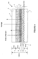
- Fig. 2 is a diagram showing the structure of an optical information recording medium according to a first embodiment.
- servo pit is formed on a polycarbonate or glass substrate 1 and is coated with aluminum, gold, platinum, etc. to provide a reflective layer 2.
- servo pit is formed on the entire surface of the substrate in Fig. 2, it can also be formed cyclically as in Fig. 1.
- the height of this servo pit is 1750 ⁇ maximum and is sufficiently small compared to the thickness of the substrate and other layers.
- a red-colored light transmitting filter layer 6 is provided on substrate 1 with reflective layer 2 and optical information recording medium 100 is constructed by sandwiching hologram recording material which is hologram recording layer 4 between this layer 6 and upper substrate 5 (polycarbonate, glass, etc).
- the red-colored light transmitting filter layer 6 transmits only red-colored light and does not pass light of other colors. Therefore, because information light and recording/reproducing reference light are green- or blue-colored light, they are not transmitted through filter 6, but become returning light without reaching reflective layer 2 and are output from incident and output surface A.
- This red-colored light transmitting filter layer 6 is, for example, a cholesteric liquid crystal layer, and Chisso Corporation-product CM-33 and the like can be used.
- cholesteric liquid crystal layer it can be placed within optical information recording medium 101, in an optical information recording medium structure wherein a quarter-wavelength board is placed between filter layer 6 (cholesteric liquid crystal layer) and incident and output surface A.
- a quarter-wavelength board is placed between dichroic mirror 13, hereafter described, and optical information recording medium 101 as an optical structure.
- This quarter-wavelength board is shifted by a quarter-wavelength for green-colored light only and when the green light incident, it becomes circularly-polarized light. However, if light of other colors (for example, red) is incident, it becomes elliptically-polarized light.
- Optical information recording medium 101 can be disk-shaped or card-shaped. If it is card-shaped, servo pit is not necessary.
- substrate 1 has a thickness of 0.6mm
- red-colored light passing filter 6 has a thickness of 2 to 3 ⁇ m
- hologram recording layer 4 has a thickness of 0.6mm
- substrate 5 has a thickness of 0.6mm. The total thickness is approximately 1.8mm.
- optical information recording medium 101 optical operations in the vicinity of optical information recording medium 101 are explained with reference to Fig. 6.
- light (red light) emitted from a servo laser is reflected 100% by dichroic mirror 13 and passes through object lens 12.
- Servo light is emitted to optical information recording medium 101 by object lens 12 such as to focus on reflective layer 2.
- dichroic mirror 13 transmits light of green- and blue-colored wavelengths and reflects light of red-colored wavelength almost 100%.
- Servo light incident on light incident and output surface A of optical information recording medium 101 is transmitted through substrate 5, hologram recording layer 4 and red-colored transmitting filter layer 6, reflected by reflective layer 2, transmitted through filter layer 6, hologram recording layer 4 and substrate 5 once again, and output from incident and output surface A.
- the output returning light is transmitted through objective lens 12 and reflected 100% by dichroic mirror 13, and servo information is detected by a servo information detector, which is not illustrated.
- the detected servo information is used for focus servo, tracking servo, slide servo and the like.
- Hologram material comprising hologram recording layer 4 does not react to red-colored light, and therefore the hologram recording layer 4 is not affected even when servo light is transmitted through hologram recording layer 4 or diffusedly reflected in reflective layer 2.
- returning light of servo light from reflective layer 2 is reflected almost 100% by dichroic mirror 13, and therefore, servo light is not detected by CMOS sensor or CCD14 for detecting reproduction image and does not interfere with reproduction light.
- information light and recording reference light generated by recording/reproduction laser pass through dichroic mirror 13 and are irradiated onto optical information recording medium 101 by object lens 11 such that information light and recording reference light generate interference patterns within hologram recording layer 4.
- Information light and recording reference light are incident from incident and output surface A, mutually interfere in hologram recording layer 4, and generate interference patterns therein.
- information light and recording reference light are transmitted through hologram recording layer 4 and incident on red-colored light transmitting filter layer 6. However, they are reflected before reaching the bottom surface of this layer and become returning light. In other words, information light and recording reference light only reach reflective layer 2 because red-colored light transmitting filter layer 6 has characteristics wherein only red-colored light is transmitted.
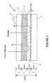
- Fig. 3 is a diagram showing the structure of an optical information recording medium according to a second embodiment.
- servo pit is formed on a polycarbonate or glass substrate 1 and is coated with aluminum, gold, platinum, etc. to provide a reflective layer 2. With regards to the height of this servo pit being a maximum of 1750 ⁇ , it is the same as in the first embodiment.
- the structural differences between the second embodiment and the first embodiment is that, in optical information recording medium 102 according to the second embodiment, there is a gap layer 8, a dichroic mirror layer 9 is provided in place of filter layer 6 of optical information recording medium 101, and furthermore, a quarter-wavelength board layer 7 is provided between dichroic mirror layer 9 and hologram recording layer 4.
- Gap layer 8 is formed on reflective layer 2 of substrate 1 by applying spin coat or the like on material such as UV range. Gap layer 8 protects reflective layer 2 as well as effectively adjusting the size of the hologram generated within hologram recording layer 4. In other words, the interference range of recording reference light and information light must be formed to a certain size in the hologram recording layer4. Therefore, it is effective to provide a gap between hologram recording layer 4 and the servo pit.
- Dichroic mirror layer 9 is formed by dielectric multilayer coating (sputtering) wavelength separation filter on gap layer 8.
- the dichroic mirror according to the second embodiment has characteristics wherein green-colored light is reflected and lights of other colors (for example, red-colored) are transmitted.
- Quarter-wavelength board layer 7 is formed by spin-coating azobenzene, for example, on dichroic mirror layer 9.
- the film generated by azobenzene is anisotropic and has characteristics wherein molecules are aligned perpendicular to the emitted polarized light.
- quarter-wavelength board layer 7 can be formed by implementing rubbing processing, as well.
- linear polarized light such as P polarized light and S polarized light is incident
- quarter-wavelength board layer 7 has characteristics wherein transmitted light is turned into circularly-polarized light from linear polarized light, if the angle of this linear polarized light is 45o to the axis of the optical system of the crystallization in the quarter-wavelength board.
- quarter-wavelength board layer 7 works to eliminate ghosts due to reflective holograms (horizontal fringe), and this layer is not necessary if the influence of ghosts can be ignored.
- substrate 1 has a thickness of 0.6mm
- gap layer 8 has a thickness of 2 to 3 ⁇ m
- dichroic mirror layer 9 has a thickness of 1 ⁇ m or smaller
- quarter-wavelength board layer 7 has a thickness of 20 ⁇ m or smaller
- hologram recording layer 4 has a thickness of 0.6mm
- substrate 5 has a thickness of 0.6mm. The total thickness is approximately 1.8mm.
- red-colored servo light, green-colored information light and recording/reproduction reference light are irradiated onto optical information recording medium 102 having a structure such as this.
- Servo light enters from incident and output surface A, passes through hologram recording layer 4, quarter-wavelength board layer 7, dichroic mirror layer 9, and gap layer 8, is reflected from reflective layer 2 and becomes returning light.
- This returning light passes through gap layer 8, dichroic mirror layer 9, quarter-wavelength board layer 7, hologram recording layer 4 and substrate 5 once again in sequential order, and exits incident and output surface A.
- the output returning light is used for focus servo, tracking servo and the like.
- the hologram material comprising hologram recording layer 4 does not react to red-colored light, and therefore, hologram recording layer 4 is not affected even when servo light passes through hologram recording layer 4 or is diffusedly reflected in reflective layer 2.
- Green-colored information light and the like enters from incident and output surface A, passes through hologram recording layer 4, quarter-wavelength board layer 7, is reflected from dichroic mirror layer 9 and becomes returning light. This returning light passes through quarter-wavelength board layer 7, hologram recording layer 4 and substrate 5 once again in sequential order, and exits incident and output surface A.
- reproduction reference light as well as reproduction light generated by irradiating hologram recording layer 4 with reproducing reference light is output from incident and output surface A without reaching reflective layer 2.
- reproduction light whether or not it is reflected by dichroic mirror layer 9 is determined by the recording method, namely, recording reflective hologram or transparent hologram.
- optical information recording medium 102 object lens 12, dichroic mirror 13 and CMOS, a detector, and CCD14
- object lens 12 dichroic mirror 13 and CMOS, a detector, and CCD14
- Fig. 4 is a diagram showing the structure of an optical information recording medium according to a third embodiment.
- a cholesteric liquid crystal layer 10 is provided in place of dichroic mirror layer 9 in the second embodiment.
- Other structures are the same as the second embodiment.
- this cholesteric liquid crystal layer 10 is also 1 to 2 ⁇ m, and as with the other embodiments, the thickness of the entire optical information recording medium is approximately 1.8mm.
- Cholesteric liquid crystal layer 10 is formed by applying, for example, cholesteric liquid crystal CM-33 (Chisso Corporation product), which is a chiral dopant, after forming gap layer (smooth layer) 8, and spin-coating.
- Cholesteric liquid crystal has characteristics wherein light is reflected when circularly-polarized light of a predetermined direction is incident, and light is transmitted when other light, for example, linear polarized light and elliptically-polarized light, is incident.
- quarter-wavelength board layer 7 has characteristics wherein it is shifted by a quarter-wavelength for only green-colored light.
- green linear polarized light information light and reference light
- red linear polarized light servo light
- green-colored information light and reference light which have been changed from linear polarized light to circularly-polarized light by quarter-wavelength board layer 7 are reflected in the cholesteric liquid crystal layer 10 and do not reach reflective layer 2.
- red-colored servo light which has been changed from linear polarized light to elliptically-polarized light by quarter-wavelength board layer 7 pass through cholesteric liquid crystal layer 10, reach reflective layer 2, and the returning light is used for focus servo, tracking servo and the like.
- Fig. 5 is a diagram showing the structure of an optical information recording medium according a fourth embodiment.
- reflective layer 2 according to the third embodiment is not a mere metallic reflective film as in A1, but is a recording medium which can be added or overwritten, such as that treated with phase-change film.
- Other structures are the same as the third embodiment, and therefore, explanations are omitted. Therefore, the effects of cholesteric liquid crystal layer 10 are the same as that in the third embodiment, and thus, explanations are omitted.
- optical information recording medium 100 having the structure in Fig. 1, because high light intensity information light and reference light (green-colored light) also converge on this reflective surface when recording holograms, ensuring reliability is problematic even when giving reflective layer 2 write function using the same red-colored light as servo light. In addition, the reflection rate of these films enabling write or over-write is not very high, and therefore, problems exist in that the reproduction efficiency of the holograms is reduced.
- reflection rate for green-colored light can be independently set by cholesteric liquid crystal layer 10 which is a wavelength separation layer through the method according to this embodiment, this is advantageous in that reflective layer 11 for red-colored light for acquiring servo can have low reflection rates.
- the two different wavelengths can be used for separate purposes without being influenced by each other.
- a polarization direction-changing layer for changing the polarization direction of light for example, a layer composed of a quarter-wavelength board, is provided between the recording layer and the filter layer.
- servo pit can be obtained from any form of pre-pit structure and is not limited to sample servo, unlike the conventional optical information recording medium in Fig. 1. Furthermore, the space between pits can be placed without being influenced by hologram size.
- the reflection rate of the reflection film for servo can be selected freely, and the material of the reflective film can also be chosen freely.
- recording medium which can be written or over-written for example DVD (digital video disk), can be used as reflective layer 11, and directory information, such as up to which area hologram is recorded and when over-write was performed, can be written and/or overwritten without affecting the hologram.
- Filter layer which is the wavelength separation layer, can be formed comparably thinner, at micron-level, and therefore, the influence of optical aberration of object lens caused by differences in the reflective surface of filter layer 6 and 9 and the reflective surface of reflective layer 2 and 11 can be ignored.
- red-colored light is implemented as servo light and green-colored light as recording/reproduction light
- red-colored light is implemented as recording/reproduction light
- blue-colored light is implemented as servo light
- red-colored light is implemented as recording/reproduction light. This is because this material reacts to red-colored light.
Landscapes
- Optical Recording Or Reproduction (AREA)
- Holo Graphy (AREA)
- Optical Record Carriers And Manufacture Thereof (AREA)
Applications Claiming Priority (5)
| Application Number | Priority Date | Filing Date | Title |
|---|---|---|---|
| US44555803P | 2003-02-06 | 2003-02-06 | |
| US445558P | 2003-02-06 | ||
| JP2003050645A JP4200026B2 (ja) | 2003-02-06 | 2003-02-27 | 光情報記録媒体 |
| JP2003050645 | 2003-02-27 | ||
| PCT/JP2004/001250 WO2004070714A1 (ja) | 2003-02-06 | 2004-02-06 | 光情報記録媒体 |
Publications (2)
| Publication Number | Publication Date |
|---|---|
| EP1596376A1 true EP1596376A1 (de) | 2005-11-16 |
| EP1596376A4 EP1596376A4 (de) | 2008-10-29 |
Family
ID=32852732
Family Applications (1)
| Application Number | Title | Priority Date | Filing Date |
|---|---|---|---|
| EP04708872A Withdrawn EP1596376A4 (de) | 2003-02-06 | 2004-02-06 | Optisches informationsaufzeichnungsmedium |
Country Status (2)
| Country | Link |
|---|---|
| EP (1) | EP1596376A4 (de) |
| WO (1) | WO2004070714A1 (de) |
Cited By (8)
| Publication number | Priority date | Publication date | Assignee | Title |
|---|---|---|---|---|
| EP1760707A3 (de) * | 2005-09-06 | 2007-12-05 | FUJIFILM Corporation | Optisches Aufzeichnungsmedium, Verfahren zu seiner Herstellung und optisches Aufzeichnungsverfahren sowie optisches Wiedergabeverfahren |
| EP1764796A3 (de) * | 2005-09-07 | 2007-12-05 | FUJIFILM Corporation | Optisches Aufzeichnungsmedium und Herstellungsverfahren dafür |
| EP1768119A3 (de) * | 2005-08-25 | 2007-12-19 | FUJIFILM Corporation | Optisches Informationsaufzeichnungsmedium, optisches Informationsaufzeichnungsverfahren und optisches Informationswiedergabeverfahren |
| EP1768120A3 (de) * | 2005-09-14 | 2008-03-05 | FUJIFILM Corporation | Optisches Aufzeichnungsmedium und Herstellungsverfahren dafür, und optisches Aufzeichnungsgerät und optisches Wiedergabegerät |
| EP1909269A4 (de) * | 2005-06-22 | 2008-11-26 | Fujifilm Corp | Optisches aufzeichnungsverfahren, optische aufzeichnungseinrichtung und optisches aufzeichnungsmedium |
| EP1981024A4 (de) * | 2006-02-03 | 2009-05-06 | Fujifilm Corp | Optisches aufzeichnungs-/wiedergabegerät, optisches aufzeichnungsverfahren und optisches wiedergabeverfahren |
| EP1965275A4 (de) * | 2005-12-22 | 2009-09-30 | Fujifilm Corp | Optisches aufzeichnungsmedium, optische aufzeichnungseinrichtung, optisches aufzeichnungsverfarhen und optisches wiedergabeverfahren |
| EP2337026A1 (de) * | 2009-12-18 | 2011-06-22 | Thomson Licensing | Optisches Aufzeichnungsmedium und Vorrichtung und Verfahren zum Lesen eines solchen Mediums |
Families Citing this family (3)
| Publication number | Priority date | Publication date | Assignee | Title |
|---|---|---|---|---|
| JP4125669B2 (ja) * | 2003-12-22 | 2008-07-30 | 大日本印刷株式会社 | 体積型ホログラム製造方法 |
| JP4373383B2 (ja) | 2005-08-24 | 2009-11-25 | 富士フイルム株式会社 | 光記録方法、光記録装置、光記録媒体及び光記録再生方法 |
| JP2007172732A (ja) * | 2005-12-21 | 2007-07-05 | Fujifilm Corp | 光情報記録媒体、情報記録方法及び情報記録システム |
Family Cites Families (11)
| Publication number | Priority date | Publication date | Assignee | Title |
|---|---|---|---|---|
| JPS59217244A (ja) * | 1983-05-24 | 1984-12-07 | Victor Co Of Japan Ltd | 情報信号記録円盤 |
| JPS61248231A (ja) * | 1985-04-25 | 1986-11-05 | Ricoh Co Ltd | 光記録方法および光記録媒体 |
| JP2796288B2 (ja) * | 1987-01-30 | 1998-09-10 | 株式会社日立製作所 | 記録媒体、その光再生方法及び光再生装置 |
| JP3453836B2 (ja) * | 1994-02-18 | 2003-10-06 | 株式会社デンソー | ホログラムの製造方法 |
| KR100465551B1 (ko) * | 1994-11-17 | 2005-04-19 | 마츠시타 덴끼 산교 가부시키가이샤 | 마킹생성장치,광디스크의레이저마킹형성방법,재생장치,광디스크및광디스크제조방법 |
| GB2296807A (en) * | 1994-12-29 | 1996-07-10 | Sharp Kk | Illumination system |
| CA2322006A1 (en) * | 1998-02-27 | 1999-09-02 | Optware Corporation | Apparatus and method for recording optical information, apparatus and method for reproducing optical information, apparatus for recording/reproducing optical information, and optical information recording medium |
| JP3393064B2 (ja) * | 1998-02-27 | 2003-04-07 | 株式会社オプトウエア | 光情報記録媒体 |
| JP3015792B1 (ja) * | 1998-12-24 | 2000-03-06 | 株式会社東芝 | 表示素子 |
| KR100691320B1 (ko) * | 2000-02-10 | 2007-03-12 | 엘지.필립스 엘시디 주식회사 | 콜레스테릭 액정 컬러필터를 갖는 반사형 액정표시장치 |
| KR100715906B1 (ko) * | 2000-12-26 | 2007-05-08 | 엘지.필립스 엘시디 주식회사 | Clc 컬러필터의 제조방법 |
-
2004
- 2004-02-06 EP EP04708872A patent/EP1596376A4/de not_active Withdrawn
- 2004-02-06 WO PCT/JP2004/001250 patent/WO2004070714A1/ja not_active Ceased
Cited By (10)
| Publication number | Priority date | Publication date | Assignee | Title |
|---|---|---|---|---|
| EP1909269A4 (de) * | 2005-06-22 | 2008-11-26 | Fujifilm Corp | Optisches aufzeichnungsverfahren, optische aufzeichnungseinrichtung und optisches aufzeichnungsmedium |
| US7742380B2 (en) | 2005-06-22 | 2010-06-22 | Fujifilm Corporation | Optical recording method, optical recording apparatus and optical recording medium |
| EP1768119A3 (de) * | 2005-08-25 | 2007-12-19 | FUJIFILM Corporation | Optisches Informationsaufzeichnungsmedium, optisches Informationsaufzeichnungsverfahren und optisches Informationswiedergabeverfahren |
| EP1760707A3 (de) * | 2005-09-06 | 2007-12-05 | FUJIFILM Corporation | Optisches Aufzeichnungsmedium, Verfahren zu seiner Herstellung und optisches Aufzeichnungsverfahren sowie optisches Wiedergabeverfahren |
| US7894319B2 (en) | 2005-09-06 | 2011-02-22 | Fujifilm Corporation | Optical recording medium, method of producing the same, and, optical recording method and optical reproducing method |
| EP1764796A3 (de) * | 2005-09-07 | 2007-12-05 | FUJIFILM Corporation | Optisches Aufzeichnungsmedium und Herstellungsverfahren dafür |
| EP1768120A3 (de) * | 2005-09-14 | 2008-03-05 | FUJIFILM Corporation | Optisches Aufzeichnungsmedium und Herstellungsverfahren dafür, und optisches Aufzeichnungsgerät und optisches Wiedergabegerät |
| EP1965275A4 (de) * | 2005-12-22 | 2009-09-30 | Fujifilm Corp | Optisches aufzeichnungsmedium, optische aufzeichnungseinrichtung, optisches aufzeichnungsverfarhen und optisches wiedergabeverfahren |
| EP1981024A4 (de) * | 2006-02-03 | 2009-05-06 | Fujifilm Corp | Optisches aufzeichnungs-/wiedergabegerät, optisches aufzeichnungsverfahren und optisches wiedergabeverfahren |
| EP2337026A1 (de) * | 2009-12-18 | 2011-06-22 | Thomson Licensing | Optisches Aufzeichnungsmedium und Vorrichtung und Verfahren zum Lesen eines solchen Mediums |
Also Published As
| Publication number | Publication date |
|---|---|
| EP1596376A4 (de) | 2008-10-29 |
| WO2004070714A1 (ja) | 2004-08-19 |
Similar Documents
| Publication | Publication Date | Title |
|---|---|---|
| US7719952B2 (en) | Optical information recording medium | |
| US5485452A (en) | Optical information recording medium | |
| EP1551011A1 (de) | Informationsaufzeichnungsverfahren, wiedergabeverfahren und aufzeichnungs-/wiedergabeverfahren mit holographie | |
| EP0520619A1 (de) | Optischer Informationsaufzeichnungsträger | |
| US7800802B2 (en) | Hologram recording medium and method for manufacturing same | |
| CN1932695B (zh) | 全息记录/再现装置和记录/再现光学设备 | |
| EP1596376A1 (de) | Optisches informationsaufzeichnungsmedium | |
| CN100388364C (zh) | 用于记录和再现全息数据的方法和全息记录介质 | |
| JPH04324133A (ja) | 光記録媒体の記録又は/及び再生装置 | |
| US20090290202A1 (en) | Hologram recording medium and hologram recording/reproduction device | |
| US8630041B2 (en) | Data storage assembly with diamond like carbon antireflective layer | |
| JP3439903B2 (ja) | 光ディスク装置用光学ヘッド | |
| JP2005032307A (ja) | 光情報記録装置 | |
| CN1229786C (zh) | 读取多层光盘的设备和方法 | |
| JPH10172171A (ja) | 開口制限素子及びこれを利用した光へッド装置 | |
| JP4461894B2 (ja) | ホログラム情報記録媒体 | |
| JP5298916B2 (ja) | 選択光学素子及び光ピックアップ装置 | |
| JP2005025906A (ja) | 光情報記録再生装置及びその方法 | |
| JP2006272654A (ja) | ホログラム記録媒体 | |
| KR100536715B1 (ko) | 홀로그래픽 롬 디스크와 이에 관련된 콤보 픽업 장치 | |
| KR19980023915A (ko) | 편광 빔 분리기(pbs) 및 이를 이용한 이종 광 디스크용 광 픽업 장치 | |
| KR100657728B1 (ko) | 홀로그래픽 롬 디스크와 디지털 데이터 디스크의 콤보 픽업 장치 및 그 장치에 사용되는 디스크 기록층 구조 | |
| TW200822096A (en) | Optical storage system | |
| JP2009099225A (ja) | 多値情報記録方法および多値情報記録装置 | |
| KR19980073038A (ko) | 편광조리개를 구비한 dvd용 광픽업장치 |
Legal Events
| Date | Code | Title | Description |
|---|---|---|---|
| PUAI | Public reference made under article 153(3) epc to a published international application that has entered the european phase |
Free format text: ORIGINAL CODE: 0009012 |
|
| 17P | Request for examination filed |
Effective date: 20050902 |
|
| AK | Designated contracting states |
Kind code of ref document: A1 Designated state(s): AT BE BG CH CY CZ DE DK EE ES FI FR GB GR HU IE IT LI LU MC NL PT RO SE SI SK TR |
|
| AX | Request for extension of the european patent |
Extension state: AL LT LV MK |
|
| DAX | Request for extension of the european patent (deleted) | ||
| RBV | Designated contracting states (corrected) |
Designated state(s): DE FR GB |
|
| A4 | Supplementary search report drawn up and despatched |
Effective date: 20080926 |
|
| STAA | Information on the status of an ep patent application or granted ep patent |
Free format text: STATUS: THE APPLICATION IS DEEMED TO BE WITHDRAWN |
|
| 18D | Application deemed to be withdrawn |
Effective date: 20081230 |