EP1596894B1 - Medizinische verbundvorrichtung - Google Patents
Medizinische verbundvorrichtung Download PDFInfo
- Publication number
- EP1596894B1 EP1596894B1 EP04714087A EP04714087A EP1596894B1 EP 1596894 B1 EP1596894 B1 EP 1596894B1 EP 04714087 A EP04714087 A EP 04714087A EP 04714087 A EP04714087 A EP 04714087A EP 1596894 B1 EP1596894 B1 EP 1596894B1
- Authority
- EP
- European Patent Office
- Prior art keywords
- medical device
- alloy
- bismuth
- opening
- section
- Prior art date
- Legal status (The legal status is an assumption and is not a legal conclusion. Google has not performed a legal analysis and makes no representation as to the accuracy of the status listed.)
- Expired - Lifetime
Links
Images


Classifications
-
- A—HUMAN NECESSITIES
- A61—MEDICAL OR VETERINARY SCIENCE; HYGIENE
- A61M—DEVICES FOR INTRODUCING MEDIA INTO, OR ONTO, THE BODY; DEVICES FOR TRANSDUCING BODY MEDIA OR FOR TAKING MEDIA FROM THE BODY; DEVICES FOR PRODUCING OR ENDING SLEEP OR STUPOR
- A61M25/00—Catheters; Hollow probes
- A61M25/01—Introducing, guiding, advancing, emplacing or holding catheters
- A61M25/09—Guide wires
-
- A—HUMAN NECESSITIES
- A61—MEDICAL OR VETERINARY SCIENCE; HYGIENE
- A61L—METHODS OR APPARATUS FOR STERILISING MATERIALS OR OBJECTS IN GENERAL; DISINFECTION, STERILISATION OR DEODORISATION OF AIR; CHEMICAL ASPECTS OF BANDAGES, DRESSINGS, ABSORBENT PADS OR SURGICAL ARTICLES; MATERIALS FOR BANDAGES, DRESSINGS, ABSORBENT PADS OR SURGICAL ARTICLES
- A61L31/00—Materials for other surgical articles, e.g. stents, stent-grafts, shunts, surgical drapes, guide wires, materials for adhesion prevention, occluding devices, surgical gloves, tissue fixation devices
- A61L31/02—Inorganic materials
- A61L31/022—Metals or alloys
-
- A—HUMAN NECESSITIES
- A61—MEDICAL OR VETERINARY SCIENCE; HYGIENE
- A61M—DEVICES FOR INTRODUCING MEDIA INTO, OR ONTO, THE BODY; DEVICES FOR TRANSDUCING BODY MEDIA OR FOR TAKING MEDIA FROM THE BODY; DEVICES FOR PRODUCING OR ENDING SLEEP OR STUPOR
- A61M25/00—Catheters; Hollow probes
- A61M25/01—Introducing, guiding, advancing, emplacing or holding catheters
- A61M25/09—Guide wires
- A61M2025/09108—Methods for making a guide wire
Definitions
- the invention generally pertains to medical devices, and more specifically to composite medical devices including two or more structural elements connected together, and a method of making the same.
- a wide variety of medical devices such as guidewires, catheters, and the like, have been developed for use in facilitating navigation and treatment throughout the anatomy of a patient. Because the anatomy of a patient may be very tortuous, it is desirable to combine a number of performance features in such a medical device. It is generally known to provide medical devices including multiple structural elements connected together to provide a number of performance features in a medical device.
- the prior art offers a number of different structures and mechanisms for connecting structural elements in medical devices. Each of these different structures and mechanisms has certain advantages and disadvantages. However, there is an ongoing need to provide alternative medical device structures and assemblies.
- the invention provides several alternative designs, materials and methods of manufacturing alternative medical device structures and assemblies.
- Weight percent, percent by weight, wt%, wt-%, % by weight, and the like are synonyms that refer to the concentration of a substance as the weight of that substance divided by the weight of the composition and multiplied by 100.
- At least some embodiments of the invention provide a medical device, or components or structures for use in a medical device; that include two or more structural elements that are connected using a bismuth alloy connector material.
- the bismuth alloy connector material is configured to expand when solidified.
- Some embodiments include a structural member defining an opening therein, and another component or structure that includes a portion that extends into the opening.
- the bismuth alloy connector material is also present within the opening, and upon solidification, the bismuth alloy connector material expands to exert a compressive force within the opening.
- the compressive force acts to connect the structural member to the other component or structure by exerting the compressive force on the inner surface of the opening of the structural member and on the portion of the other component or structure that extends into the opening.
- a mechanical interlock is thereby provided between the structural member and the other component or structure.
- the use of such a bismuth alloy connector material can provide for some advantages.
- the connection provided by the using such material does not depend on alloying with, or chemically adhering to the materials of the components being connected, there is less of a concern regarding providing surfaces to be attached that are absolutely free of contaminants or surface oxides.
- conventional preparation of surfaces of some materials that are to be connected may require a substantial amount of treatment or preparation
- many such treatments or preparations are not necessary in at least some embodiments using a bismuth alloy connector material.
- This can be advantageous for many reasons, especially in situations where the components to be connected are difficult to expose to such treatments.
- some components may be very small, or may include portions that are physically difficult to reach with such treatments or preparations.
- some components may be made of materials that do not react well with , or cannot be exposed to harsh preparation or treatment methods.
- the structural member is a connector member that is particularly adapted and configured to interconnect two or more other components or structures.
- the structural member may be a connector tube that is particularly adapted and configured to have portions of other structures, such as the ends of elongated members such as wires or hypotubes, inserted therein for connection using the bismuth alloy connector material.
- the structural member is a component of the medical device that includes an opening or aperture on a portion thereof that is adapted and configured for use in connecting the structural member with other components of the device using the bismuth alloy connector material.
- the structural member may be a wire or hypotube defining an opening or lumen in the end thereof, or other such structure.
- the invention may be applicable to almost any medical device.
- the invention may be applicable to shafts for catheters (e.g., guide catheters, balloon catheters, stent delivery catheters, etc.), infusion devices, distal protection devices, or shafts for rotational devices (atherectomy catheters, IVUS catheters, etc.).
- the medical device is particularly adapted and configured for use in intravascular applications.
- Figures 1-4 illustrate cross sectional views of a portion of a guidewire 10 including a connection 20 joining a proximal guidewire section 14 and a distal guidewire section 16.
- Figure 1 illustrates the guidewire 10 and the connection 20 before a final grinding step
- Figure 2 illustrates the guidewire 10 and the connection 20 after the final grinding step, which provides a smooth outer profile.
- the embodiment of Figures 1 and 2 utilizes an overlapping tapered joint 12, a connector structure 18 and a bismuth alloy connector material 30.
- the embodiment of Figure 3 is similar to the embodiment of Figures 1 and 2, except that the connection 20 between the proximal guidewire section 14 and the distal guidewire section 16 does not utilize an overlapping joint 12, but rather uses a butt joint 13.
- the embodiment of Figure 4 is also similar to the embodiment of Figures 1 and 2, except that the connection 20 between the proximal guidewire section 14 and the distal guidewire section 16 utilizes an overlapping joint 12 that is not tapered.
- proximal/distal guidewire sections 14/16 are dictated primary by the desired characteristics and function of the final guidewire, and that any of a broad range of materials, structures, and dimensions can be used.
- the proximal and distal guidewire sections 14/16 may have a solid cross-section as shown, or a hollow cross-section, and may be formed of any materials suitable for use, dependent upon the desired properties of the guidewire.
- suitable materials include metals, metal alloys, and polymers.
- the proximal section 14 and the distal section 16 may generically refer to any two adjacent guidewire sections along any portion of the guidewire.
- proximal guidewire section 14 may be formed of relatively stiff material such as straightened 304v stainless steel wire.
- proximal portion 14 may be comprised of a metal or metal alloy such as a nickel-titanium alloy, nickel-chromium alloy, nickel-chromium-iron alloy, cobalt alloy, a polymer material, such as a high performance polymer, or other suitable material, or the like.
- the material used to construct proximal portion 14 may be selected to be relatively stiff for pushability and torqueability.
- the distal guidewire section 16 may be formed of a relatively flexible material such as a straightened super elastic (i.e. pseudoelastic) or linear elastic alloy (e.g., nickel-titanium) wire, or a alternatively, a polymer material, such as a high performance polymer, or similar such material or the like.
- distal portion 16 may be comprised of a metal or metal alloy such as stainless steel, nickel-chromium alloy, nickel-chromium-iron alloy, cobalt alloy, or other suitable material.
- the material used to construct distal portion 16 may be selected to be relatively flexible for trackability.
- the distal section 16 is a linear elastic nickel-titanium alloy, for example, linear elastic nitinol.
- linear elastic nitinol was coined by a group of researchers at the United States Naval Ordinance Laboratory (NOL) who were the first to observe the shape memory behavior of this material.
- NOL United States Naval Ordinance Laboratory
- the word nitinol is an acronym including the chemical symbol for nickel (Ni), the chemical symbol for titanium (Ti), and an acronym identifying the Naval Ordinance Laboratory (NOL).
- linear elastic Within the family of commercially available nitinol alloys, is a category designated "linear elastic” which, although is similar in chemistry to conventional shape memory and superelastic varieties, exhibits distinct and useful mechanical properties.
- the wire By skilled applications of cold work, directional stress, and heat treatment, the wire is fabricated in such a way that it does not display a substantial "superelastic plateau” or “flat region” in its stress/strain curve. Instead, as recoverable strain increases, the stress continues to increase in an essentially linear relationship until plastic deformation begins.
- the linear elastic nickel-titanium alloy is an alloy that does not show any martensite/austenite phase changes that are detectable by DSC and DMTA analysis over a large temperature range.
- the mechanical bending properties of such material are therefore generally inert to the effect of temperature over this very broad range of temperature.
- the mechanical properties of the alloy at ambient or room temperature are substantially the same as the mechanical properties at body temperature.
- the use of the linear elastic nickel-titanium alloy for the distal portion 16 allows the guidewire to exhibit superior "pushability" around tortuous anatomy.
- the linear elastic nickel-titanium alloy comprises in the range of about 50 to about 60 wt.% nickel, with the remainder being essentially titanium. In some particular embodiments, the composition comprises in the range of about 54 to about 57 wt. % nickel.
- a suitable nickel-titanium alloy is FHP-NT alloy commercially available from Furukawa Techno Material Co. of Kanagawa, Japan. Some examples of nickel-titanium alloys are disclosed in U.S. Patent Nos. 5,238,004 and 6,508,803.
- the proximal guidewire section 14 is formed from a stainless steel wire having a diameter in the range of 0.01 to 0.02 inches, and a length in the range of about 50 to about 110 inches
- the distal guidewire section 16 is formed from a linear elastic nitinol wire having a diameter that ranges from a diameter to match the diameter of the proximal guidewire section 14 to as small as about 0.002 inches, and a length in the range of 3 to 15 inches.
- the distal end 24 of the proximal portion 14 and the proximal end 26 of distal portion 16 may form an overlapping tapered joint 12 as shown in Figures 1 - 2.
- the joined ends 24/26 may form a butt joint 13 as shown in Figure 3.
- the joined ends 24/26 in the butt joint 13 can be in direct contact with each other, or can include a degree of spacing between the joined ends, as shown in Figure 3.
- the joined ends 24/26 may form an overlapping joint 12 that is not tapered as shown in Figure 4.
- the one or both of the non-tapered end portions 24/26 may have a uniform profile (diameter) 23 as shown in Figure 5A, a bulbous portion 25 for purposes of mechanical interlocking as shown in Figure 5B, or a helical form 27 for purposes of mechanical interlocking as shown in Figure 5C. Additionally, in some embodiments, using either an overlapping type joint or using a butt type joint, portions of the outer surfaces of either of the joined ends can be provided with additional structures, such as grooves, ridges, a roughened or textured surface, or the like for the purpose of providing better mechanical interlocking between the joined ends and the connector structure or connector material.
- the end portions 24/26 overlap to form an overlapping joint 12.
- the overlapping joint 12 can act to blend the stiffness of proximal portion 14 and distal portion 16, if desired, by combining the properties of each end section 24/26 making up the cross section of the overlapping joint 12.
- the joint 12 forms a flexibility transition region that has a relative flexibility that is between the flexibility of the proximal portion 14 and the flexibility of the distal portion 16.
- the ends 24/26 may be tapered or otherwise formed to have a mating geometry that gradually decreases in cross sectional area toward the middle of the connection 20.
- the tapered overlapping portion 12 may define a uniform or a non-uniform transition of the sections 24/26, depending on the transition characteristics desired.
- the end sections 24/26 may be linearly tapered as shown, tapered in a curvilinear fashion, or tapered in a step-wise fashion. If tapered linearly as shown, the angle of the taper may vary.
- the angle of the taper is acute (i.e., less than 90 degrees), and may be in the range of 5 degrees to 45 degrees, for example. Varying the angle of the tapered ends 24/26 also varies the length of the overlapping joint 12 in accordance with geometric principles. The length of the overlapping joint 12 may be selected to obtain a more (longer length) or less (shorter length) gradual transition in stiffness.
- the proximal guidewire section 14 and the distal guidewire section 16 may be formed of different materials (i.e., materials having different moduli of elasticity) resulting in a difference in flexibility.
- the proximal guidewire section 14 may be formed of stainless steel wire and the distal guidewire section 16 may be formed of nickel-titanium alloy wire, both having the same dimensions, resulting in a 3:1 difference in elastic modulus.
- Such a difference in elastic modulus i.e., flexibility
- stress is distributed along the entire length of the connection 20 thereby decreasing the probability that guidewire 10 may kink at the junction.
- connection 20 may be located further distally.
- the distal portion 16 may be manufactured to be shorter than proximal portion 14. Including a relatively long proximal section 14 may advantageously increase the torquability and pushability of the guidewire 10.
- additional connections 20 may be used to connect other guidewire sections of varying stiffness.
- the connector structure 18 may comprise a structure defining one or more openings therein or one or more lumens extending there through.
- the connector structure 18 is a generally tubular structure such as a hypotube as shown, or a coiled wire, or the like.
- the connector 18 may have an inside diameter sized and shaped appropriately to receive the ends 24/26 of the proximal portion 14 and the distal portion 16, and an outside diameter sufficient to accommodate a final grinding procedure.
- the outside surface of the connector structure is generally circular in cross-sectional shape, however, other geometries, for example, oval, or multisided geometries may be used in other embodiments.
- the connector 18 can include one or more grooves, slits, slots, or the like, that are defined in the body of the connector, for example, to provide a desired degree of flexibility characteristics to the connector 18.
- Some examples of such structures are disclosed in a U.S. Patent Application entitled “ARTICULATING INTRACORPORAL MEDICAL DEVICE” (Attorney docket no. 1001.1668101) filed on even date herewith.
- Some other examples of suitable techniques and structures that can be used to interconnect different shaft sections are disclosed in U.S. Patent Application Nos. 09/972,276 filed on October 5, 2001 and 10/068,992 filed on February 28, 2002.
- the connector 18 is generally tubular, and can have an inner diameter in the range of 0.127 (0.005) to 0.508 mm (0.02 inches), and an outer diameter in the range of 0.254 (0.01) to 0.635 mm (0.025 inches). In some particular embodiments, the connector 18 can have an inner diameter of about 0.254 (0.010) mm (inches) and an outer diameter of about 0.014 inches. The final diameter of the guidewire 10 and the connector 18 may be in the range of 0.254 (0.010) to 0.457mm (0.018 inches) for example.
- the connector 18 may have a length of about 2.54 (1.0) to 7.62 cm (3.0 inches) for an overlapping portion 12 of about 6.35 (0.25) to 63.5 mm (2.5 inches).
- this type of construction can be applied to wires or other structures of larger diameter intended, for example, for peripheral intervention purposes. Such wires could range as large as .035 in diameter and therefore have an extended length connector and correspondingly longer overlapping sections.
- the connector 18 may include or be made of a metal or metal alloy, and may include radiopaque materials. Suitable metals and metal alloys include stainless steels, nickel-titanium alloys (e.g., nitinol), nickel-chromium alloys, nickel-chromium-iron alloys, cobalt alloys, nickel, or other suitable materials, and the like.
- nickel-chromium-iron alloy designated UNS N06625 and is available under the trade name INCONEL 625, which may be obtained from California Fine Wire Company of Grover Beach, California.
- connector 18 may be comprised of a polymer or a metal-polymer composite, and the like.
- the connector 18, or portions thereof can also be made of or include a radiopaque material.
- Radiopaque materials are understood to be materials capable of producing a relatively bright image on a fluoroscopy screen or another imaging technique during a medical procedure. This relatively bright image aids the user of device 10 in determining its location.
- Some examples of radiopaque materials can include, but are not limited to, gold, platinum, palladium, tantalum, tungsten alloy, plastic material loaded with a radiopaque filler, and the like.
- the connector structure may be part of, or integral with, one of the structural elements being connected together.
- the connector structure could be defined by an end of a wire or hypotube that includes an opening, recess, or lumen defined therein, into which the bismuth alloy connector material and the end of another structure are inserted for connection thereto.
- the connector structure may be attached to one of the structures being connected together using more conventional techniques, such as adhesive bonding, thermal bonding, soldering, brazing, welding, mechanical connection (e.g. crimping, friction fitting, etc...), while being connected to another structures using the bismuth alloy connector material as discussed herein.
- the bismuth alloy connector materials for example connector material 30, for use in making the connection are adapted and configured to have the characteristic of expansion or growth upon or after solidification.
- the crystalline structure that forms during solidification occupies a larger volume than the same mass of liquid.
- suitable bismuth alloy connector materials include alloys of bismuth including additional alloying elements such as tin, indium, cadmium, lead, and the like. Due to the fact that the final medical device will make contact with or be inserted into a living body, in some embodiments, the alloy should include only elements that are known to be acceptable for contact with the body. For example, bismuth alloys including elements such as tin, indium, or the like, may be more acceptable for contact with the body. Some example alloys can include in the range of about 4 to about 80 wt. % bismuth, with the remainder being other alloying elements. Some examples of suitable alloys, and example ranges of wt.
- % of components within some alloys include those having the ranges of components as illustrated in Table 1 as follows:
- Table 1 Type of alloy Range of components in some embodiments: One example of a specific alloy falling within these ranges: Bismuth-Tin alloy 35 to 45 wt. % Bi, and 40 wt. Bi, and 55 to 65 wt. % Sn 60 wt. % Sn Bismuth-Tin alloy 53 to 63 wt. % Bi, and 58 wt. % Bi, and 37 to 47 wt. % Sn 42 wt. % Sn Bismuth-Indium alloy 2 to 10 wt. % Bi, and 5 wt.
- the bismuth alloys that can be used as the connector material are characterized by relatively low melting temperatures compared to some other metal alloys.
- the bismuth alloy used is characterized as being a "fusible" alloy, meaning that it has a melting point in the range of about 50 to about 260°C.
- the alloy has a melting point in the range of about 200°C or below, or in the range of about 150°C or below.
- the alloy used is the eutectic alloy for the particular type of alloy being used, meaning that it is the particular alloy having the lowest melting point (i.e. eutectic point) that is obtainable by varying the proportions of the components of the alloy.
- Eutectic alloys have definite and minimum melting points in contrast to other combinations of the same metals. For such eutectic alloys, the minimum melting points as given above would be the eutectic melting point.
- the low melting temperatures can be useful when the connector material is used in conjunction with structural elements that are made of or include temperature sensitive material.
- some nickel-titanium alloys are annealed or shape set by exposure to higher temperatures. Therefore, the use of alloys having a lower temperature melting point can help to preserve the desired heat-treat state of structures made of such nickel-titanium alloys that need to be connected to other structures.
- the ends 24/26 of the proximal and distal guidewire sections 14/16 may be ground or otherwise worked to form the desired size and shape (e.g., uniform diameter 23, bulbous portion 25, helix 27, taper, or mechanical interlocking features, such as grooves, ridges, roughened surfaces, etc.) to accommodate the size and shape of the connector structure 18, or to accommodate the type of joint being constructed (e.g. an overlapping joint, a butt joint, etc.).
- the size and shape of the ends 24/26 and the connector structure 18 can be configured to allow for the inclusion of the bismuth alloy connector material 30, and for the flow of the connector material in a liquid state.
- a recess step may be ground into the proximal and distal guidewire sections 14/16 to accommodate the connector structure, such as the connector tube 18.
- the ends 24/26 of the proximal and distal guidewire sections 14/16 and the bismuth alloy connector material 30 are disposed within the lumen defined in the connector structure 18 in such a manner that the bismuth alloy connector material 30 solidifies and expands to exert a compressive force within the lumen.
- the compressive force within the lumen acts to connect the connector structure 18 to the ends 24/26 of the proximal and distal guidewire sections 14/16, and thereby connect the proximal and distal guidewire sections 14/16 to each other.
- the ends 24/26 of the proximal and distal guidewire sections 14/16 and the bismuth alloy connector material 30 can be disposed within the lumen of the connector structure 18 using any suitable process or method that allows for such a connection to be formed.
- a sufficient amount of the bismuth alloy connector material is applied to either one or both ends 24/26 of the proximal and distal guidewire sections 14/16, and bismuth alloy connector material is allowed to solidify.
- the bismuth alloy connector material can be applied to the ends 24/26 using any suitable process, for example, a hot dipping process, a coating process, a spraying process, a plating process, or the like. The ends 24/26 are then inserted into the lumen within the connector tube 18 until a dimensional interference is created.
- the bismuth alloy connector material is then heated above its melting point of the bismuth alloy connector material, and an additional insertion force is applied to the guidewire sections 14/16 to provide axial movement of the ends 24/26 further into the connector structure and into a bonding position.
- the distal end 24 of the proximal portion 14 and proximal end 26 of the distal portion 16 can be positioned adjacent one another in an overlapping 12 or an end-to-end 13 arrangement within the connector structure 18.
- some excess bismuth alloy connector material may be displaced from within the lumen in the connector structure 18, indicating that the opening or lumen if full to capacity.
- the bismuth alloy connector material 30 is allowed to cool and solidify within the lumen.
- the compressive force within the lumen acts to provide a mechanical interlock between the connector structure 18 to the ends 24/26 of the proximal and distal guidewire sections 14/16, and thereby connect the proximal and distal guidewire sections 14/16 to each other.
- the bismuth alloy that may solidify outside of the connector 18 can serve to form or function as strain relief just proximal and distal of the connector. In some embodiments, bismuth alloy that may solidify outside of the connector 18 may have a constant diameter, which can be beneficial for strain relief.
- a sufficient amount of the bismuth alloy connector material can be applied to either one or both ends 24/26 of the proximal and distal guidewire sections 14/16, and either one or both ends 24/26 are inserted into a bonding position within the lumen within the connector tube 18 prior to solidification of the bismuth alloy connector material.
- the bismuth alloy connector material 30 can then be allowed to cool, solidify, and expand to provide a connection as discussed above.
- Another alternative method can entail disposing the bismuth alloy connector material within the lumen of the connector structure 18 prior to insertion of the ends 24/26 into the lumen.
- the ends 24/26 can be inserted in a bonding position within the lumen prior to solidification of the bismuth alloy connector material.
- the bismuth alloy connector material can be allowed to solidify, and is then reheated prior to or during the insertion of the ends 24/26 into a bonding position within the lumen.
- the bismuth alloy connector material 30 can then be allowed to cool, solidify, and expand to provide a connection as discussed above.
- the joint can be disconnected, or reworked by reheating the connector material and separating or reworking the components of the joint.
- the connector tube 18 and the proximal and distal guidewire sections 14/16 can be worked or formed to provide desired characteristics, such as shape or flexibility characteristics.
- connector tube 18 and the proximal and distal guidewire sections 14/16 can be centerless ground to provide a smooth and uniform profile across the connection 20, and to straighten out small misalignments between the proximal and distal guidewire sections 14/16.
- Other portions of the guidewire 10 may be ground as well to provide the desired tapers and changes in diameter.
- one or both of the proximal and distal guidewire sections 14/16 can be continuously tapered, can have a tapered section or a number or series of tapered sections of differing diameters, or can have a constant diameter.
- the sections 14/16 are tapered or otherwise formed to have a geometry that decreases in cross sectional area toward the distal end thereof. If tapered, the sections 14/16 can include a uniform or a non-uniform transition of the sections, depending on the transition characteristics desired. For example, one or both of the sections 14/16 may be linearly tapered, tapered in a curvilinear fashion, or tapered in a step-wise fashion. The angle of any such tapers can vary, depending upon the desired flexibility characteristics. The length of the taper may be selected to obtain a more (longer length) or less (shorter length) gradual transition in stiffness.
- the centerless grinding technique may utilize an indexing system employing sensors (e.g., optical/reflective, magnetic) to avoid excessive grinding of the connection 20.
- sensors e.g., optical/reflective, magnetic
- the presence of dissimilar materials in the construction can influence the grinding technique and tooling used to accomplish uniform material removal, create smooth transitions, and successfully bridge across adjacent components.
- the centerless grinding technique may utilize a CBN or diamond abrasive grinding wheel that is well shaped and dressed to avoid grabbing the connector 20 during the grinding process.
- a flexible coil such as a coil tip
- a polymer jacket such as a polymer tip
- other such structure such as radiopaque markers, safety and/or shaping ribbons (coiled or uncoiled), and the like
- guidewire constructions for example tip constructions, are disclosed in U.S. Patent Application Number 10/068,992 filed February 28, 2002, entitled “Composite Guidewire”.
- a coating for example a lubricious (e.g., hydrophylic) or other type of coating may be applied to all or portions of the guidewire. Different coatings can be applied to different sections of the guidewire. Some examples of such coatings and materials and methods used to create such coatings can be found in U.S. Patent Nos. 6,139,510 and 5,772,609.
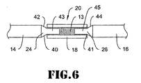
- FIG. 6 illustrates another example embodiment similar to the embodiment of Figure 3, except that the connection 20 between the proximal guidewire section 14 and the distal guidewire section 16 uses a butt type joint 13, but wherein the joined ends 24/26 are spaced from one another.
- the joined ends 24/26 include reduced diameter portions 40 and 41.
- the reduced diameter portion 40 includes tapering portion 42 and constant diameter portion 43.
- Reduced diameter portion 41 includes tapering portion 44 and constant diameter portion 45.
- the constant diameter portions 43 and 45 are configured to fit within the connector 18, and are attached to the connector 18 using a bismuth fusible alloy material, as discussed above.
Landscapes
- Health & Medical Sciences (AREA)
- Life Sciences & Earth Sciences (AREA)
- Heart & Thoracic Surgery (AREA)
- Veterinary Medicine (AREA)
- Public Health (AREA)
- General Health & Medical Sciences (AREA)
- Animal Behavior & Ethology (AREA)
- Biomedical Technology (AREA)
- Vascular Medicine (AREA)
- Anesthesiology (AREA)
- Engineering & Computer Science (AREA)
- Pulmonology (AREA)
- Biophysics (AREA)
- Chemical & Material Sciences (AREA)
- Inorganic Chemistry (AREA)
- Surgery (AREA)
- Hematology (AREA)
- Epidemiology (AREA)
- Media Introduction/Drainage Providing Device (AREA)
- Materials For Medical Uses (AREA)
- Surgical Instruments (AREA)
- Radiation-Therapy Devices (AREA)
- Electrotherapy Devices (AREA)
- Prostheses (AREA)
Claims (34)
- Medizinische Vorrichtung mit:einem länglichen Abschnitt mit einem Ende;einem Strukturteil, das eine Öffnung darin bildet, wobei sich das Ende des länglichen Abschnitts in die Öffnung erstreckt; undeinem Verbindermaterial aus Wismutlegierung, das in der Öffnung angeordnet ist, wobei das Verbindermaterial so konfiguriert ist, daß es sich beim Erstarren ausdehnt, um eine Druckkraft in der Öffnung in dem Abschnitt auszuüben.
- Medizinische Vorrichtung nach Anspruch 1, wobei das Verbindermaterial aus Wismutlegierung erstarrt ist und sich ausgedehnt hat, um eine Druckkraft auf das Strukturteil und das Ende des länglichen Abschnitts auszuüben, um für eine mechanische Verriegelung zwischen dem Strukturteil und dem länglichen Abschnitt zu sorgen.
- Medizinische Vorrichtung nach Anspruch 1, wobei das Strukturteil eine zweite Öffnung darin bildet und die medizinische Vorrichtung ferner aufweist: einen zweiten länglichen Abschnitt mit einem Ende, wobei sich das Ende des zweiten länglichen Abschnitts in die zweite Öffnung erstreckt; und
ein Verbindermaterial aus Wismutlegierung, das in der zweiten Öffnung angeordnet ist, wobei das Verbindermaterial so konfiguriert ist, daß es sich beim Erstarren ausdehnt, um eine Druckkraft im Strukturteil auszuüben. - Medizinische Vorrichtung nach Anspruch 3, wobei die erste Öffnung und die zweite Öffnung Öffnungen an den entgegengesetzten Enden eines gemeinsamen Lumens sind, das im Strukturteil gebildet ist.
- Medizinische Vorrichtung nach Anspruch 4, wobei der erste längliche Abschnitt einen proximalen Abschnitt mit einem distalen Ende aufweist, der zweite längliche Abschnitt einen distalen Abschnitt mit einem proximalen Ende aufweist; und das Strukturteil ein Verbinderteil aufweist, das das Lumen mit der ersten Öffnung und der zweiten Öffnung bildet, wobei sich das distale Ende des proximalen Abschnitts in das Lumen durch die erste Öffnung erstreckt, und sich das proximale Ende des distalen Abschnitts in das Lumen durch die zweite Öffnung erstreckt, und das Verbindermaterial aus Wismutlegierung im Lumen angeordnet ist und das Verbindermaterial so konfiguriert ist, daß es sich beim Erstarren ausdehnt, um Druckkräfte im Verbinderteil auszuüben.
- Medizinische Vorrichtung nach einem der Ansprüche 1 bis 5, wobei das Verbindermaterial aus Wismutlegierung einen eutektischen Schmelzpunkt im Bereich von 200 °C oder darunter hat oder alternativ das Verbindermaterial aus Wismutlegierung einen eutektischen Schmelzpunkt im Bereich von 150 °C oder darunter hat.
- Medizinische Vorrichtung nach einem der Ansprüche 1 bis 6, wobei das Verbindermaterial aus Wismutlegierung Wismut im Bereich von 4 bis 80 Gew.-% aufweist.
- Medizinische Vorrichtung nach einem der Ansprüche 1 bis 7, wobei das Verbindermaterial aus Wismutlegierung Wismut und ein zusätzliches Legierungselement aufweist, das aus Zinn, Indium oder deren Mischungen ausgewählt ist.
- Medizinische Vorrichtung nach einem der Ansprüche 1 bis 8, wobei das Verbindermaterial aus Wismutlegierung Wismut im Bereich von 35 bis 45 Gew.-% und Zinn im Bereich von 55 bis 65 Gew.-% aufweist oder alternativ das Verbindermaterial aus Wismutlegierung Wismut im Bereich von 53 bis 63 Gew.-% und zinn im Bereich von 37 bis 47 Gew.-% aufweist.
- Medizinische Vorrichtung nach einem der Ansprüche 1 bis 9, wobei das Verbindermaterial aus Wismutlegierung eine eutektische Wismut-Zinn-Legierung aufweist.
- Medizinische Vorrichtung nach einem der Ansprüche 1 bis 8, wobei das Verbindermaterial aus Wismutlegierung Wismut im Bereich von 2 bis 10 Gew.-% und Indium im Bereich von 90 bis 98 Gew.-% aufweist oder alternativ das Verbindermaterial aus Wismutlegierung Wismut im Bereich von 62 bis 72 Gew.-% und Indium im Bereich von 28 bis 38 Gew.-% aufweist oder alternativ das Verbindermaterial aus Wismutlegierung Wismut im Bereich von 29 bis 39 Gew.-% und Indium im Bereich von 61 bis 71 Gew.-% aufweist.
- Medizinische Vorrichtung nach einem der Ansprüche 1 bis 8 oder 11, wobei das Verbindermaterial aus Wismutlegierung eine eutektische Wismut-Indium-Legierung aufweist.
- Medizinische Vorrichtung nach einem der Ansprüche 1 bis 8, wobei das Verbindermaterial aus Wismutlegierung Wismut im Bereich von 53 bis 63 Gew.-%, Indium im Bereich von 20 bis 30 Gew.-% und Zinn im Bereich von 12 bis 22 Gew.-% aufweist.
- Medizinische Vorrichtung nach einem der Ansprüche 1 bis 8 oder 13, wobei das Verbindermaterial aus Wismutlegierung eine eutektische Wismut-Indium-Zinn-Legierung aufweist.
- Medizinische Vorrichtung nach Anspruch 5, wobei das Verbindermaterial aus Wismutlegierung erstarrt ist und sich ausgedehnt hat, um eine Druckkraft auf das Verbinderteil sowie das distale Ende des proximalen Abschnitts und das proximale Ende des distalen Abschnitts auszuüben, um für eine mechanische Verriegelung zwischen dem Verbinderteil und den Enden der länglichen Abschnitte zu sorgen.
- Medizinische Vorrichtung nach Anspruch 5 oder 15, wobei der proximale Abschnitt eine erste Flexibilität hat und der distale Abschnitt eine zweite Flexibilität hat und wobei sich das distale Ende des proximalen Abschnitts und das proximale Ende des distalen Abschnitts überlappen, um einen Bereich zu bilden, in dem die erste Flexibilität und die zweite Flexibilität ineinander übergehen.
- Medizinische Vorrichtung nach Anspruch 5, 15 oder 16, wobei das distale Ende des proximalen Abschnitts eine reduzierte Größe hat und das proximale Ende des distalen Abschnitts eine reduzierte Größe hat.
- Medizinische Vorrichtung nach Anspruch 17, wobei die Teile mit reduzierter Größe ein gleichmäßiges Profil haben.
- Medizinische Vorrichtung nach Anspruch 17, wobei die Teile mit reduzierter Größe eine Verjüngung haben.
- Medizinische Vorrichtung nach Anspruch 17, wobei die Teile mit reduzierter Größe eine ineinandergreifende Form haben.
- Medizinische Vorrichtung nach Anspruch 5 oder 15, wobei das distale Ende des proximalen Abschnitts und das proximale Ende des distalen Abschnitts so zusammengefügt sind, daß sie einen Stumpfstoß im Verbinderteil bilden.
- Medizinische Vorrichtung nach Anspruch 5 oder 15 bis 20, wobei das distale Ende des proximalen Abschnitts ein zulaufendes Teil bildet und das proximale Ende des distalen Abschnitts ein zulaufendes Teil bildet und sich die zulaufenden Teile mindestens teilweise überlappen.
- Medizinische Vorrichtung nach einem der Ansprüche 1 bis 22, wobei der längliche Abschnitt ein Metall oder eine Metallegierung aufweist und optional das Metall oder die Metallegierung Edelstahl, Nickel-Titan-Legierung, Nickel-Chrom-Legierung, Nickel-Chrom-Eisen-Legierung, Kobaltlegierung oder deren Kombinationen aufweist.
- Medizinische Vorrichtung nach einem der Ansprüche 5 oder 15 bis 22, wobei die medizinische Vorrichtung ferner eine Außenstruktür aufweist, die um mindestens einen Teil des distalen Abschnitts angeordnet ist.
- Medizinische Vorrichtung nach einem der Ansprüche 1 bis 24, wobei das Strukturteil ein Metall oder eine Metalllegierung aufweist und optional das Metall oder die Metallegierung Edelstahl, Nickel-Titan-Legierung, Nickel-Chrom-Legierung, Nickel-Chrom-Eisen-Legierung, Kobaltlegierung, Nickel oder deren Kombinationen aufweist.
- Medizinische Vorrichtung nach einem der Ansprüche 1 bis 24, wobei das Strukturteil ein Polymer oder einen Metall-Polymer-Verbundstoff aufweist.
- Medizinische Vorrichtung nach einem der Ansprüche 5 oder 15 bis 22, wobei die Verbinderstruktur ein Röhrenteil aufweist, das um das distale Ende des proximalen Abschnitts und das proximale Ende des distalen Abschnitts angeordnet ist.
- Medizinische Vorrichtung nach einem der Ansprüche 3 bis 5 oder 15 bis 22, wobei der zweite längliche Abschnitt ein Metall oder eine Metallegierung aufweist und optional das Metall oder die Metallegierung Edelstahl, Nickel-Titan-Legierung, Nickel-Chrom-Legierung, Nickel-Chrom-Eisen-Legierung, Kobaltlegierung oder deren Kombinationen aufweist.
- Medizinische Vorrichtung nach einem der Ansprüche 1 bis 28, wobei die medizinische Vorrichtung einen Führungsdraht aufweist.
- Führungsdraht mit:einem proximalen Abschnitt mit einem distalen Ende;einem distalen Abschnitt mit einem proximalen Ende; undeiner Verbinderstruktur, die benachbart zum distalen Ende des proximalen Abschnitts und zum proximalen Ende des distalen Abschnitts angeordnet ist; undeiner Einrichtung zum Ausüben einer Druckkraft auf die Verbinderstruktur und die Enden des proximalen und distalen Abschnitts, um für eine mechanische Verriegelung zwischen der Verbinderstruktur und dem proximalen und distalen Abschnitts zu sorgen, wobei die Einrichtung ein Verbindermaterial aus Wismutlegierung aufweist.
- Verfahren zur Herstellung der medizinischen Vorrichtung nach einem der Ansprüche 1 bis 29, wobei das Verfahren die folgenden Schritte aufweist:Bereitstellen des länglichen Abschnitts mit dem Ende;Bereitstellen des Strukturteils, das die Öffnung darin bildet;Anordnen des Endes des länglichen Abschnitts in der Öffnung;Anordnen des Verbindermaterials aus Wismutlegierung in der Öffnung; undErstarren- und Ausdehnenlassen des Verbindermaterials aus Wismutlegierung, um eine Druckkraft in der Öffnung im Strukturteil auszuüben.
- Verfahren zur Herstellung der medizinischen Vorrichtung nach einem der Ansprüche 3 bis 5, 15 bis 24 oder 27 bis 28, wobei das Verfahren die folgenden Schritte aufweist:Bereitstellen des ersten länglichen Abschnitts mit dem Ende;Bereitstellen des zweiten länglichen Abschnitts mit dem Ende;Bereitstellen des Strukturteils, das die erste Öffnung und zweite Öffnung darin bildet;Anordnen des Endes des ersten länglichen Abschnitts in der ersten Öffnung;Anordnen des Endes des zweiten länglichen Abschnitts in der zweiten Öffnung;Anordnen des Verbindermaterials aus Wismutlegierung in der ersten Öffnung und der zweiten Öffnung; undErstarren- und Ausdehnenlassen des Verbindermaterials aus Wismutlegierung, um eine Druckkraft in der erstenÖffnung und der zweiten Öffnung im Strukturteil auszuüben.
- Verfahren nach Anspruch 32, wobei die erste Öffnung und die zweite Öffnung Öffnungen an den entgegengesetzten Enden eines gemeinsamen Lumens sind, das im Strukturteil gebildet ist.
- Verfahren nach Anspruch 32 oder 33, wobei die medizinische Vorrichtung einen Führungsdraht aufweist.
Applications Claiming Priority (3)
| Application Number | Priority Date | Filing Date | Title |
|---|---|---|---|
| US10/375,766 US20040167441A1 (en) | 2003-02-26 | 2003-02-26 | Composite medical device |
| US375766 | 2003-02-26 | ||
| PCT/US2004/005343 WO2004075941A1 (en) | 2003-02-26 | 2004-02-24 | Composite medical device |
Publications (2)
| Publication Number | Publication Date |
|---|---|
| EP1596894A1 EP1596894A1 (de) | 2005-11-23 |
| EP1596894B1 true EP1596894B1 (de) | 2006-06-28 |
Family
ID=32869036
Family Applications (1)
| Application Number | Title | Priority Date | Filing Date |
|---|---|---|---|
| EP04714087A Expired - Lifetime EP1596894B1 (de) | 2003-02-26 | 2004-02-24 | Medizinische verbundvorrichtung |
Country Status (8)
| Country | Link |
|---|---|
| US (1) | US20040167441A1 (de) |
| EP (1) | EP1596894B1 (de) |
| JP (1) | JP2006519059A (de) |
| AT (1) | ATE331539T1 (de) |
| CA (1) | CA2515383C (de) |
| DE (1) | DE602004001394T2 (de) |
| ES (1) | ES2267054T3 (de) |
| WO (1) | WO2004075941A1 (de) |
Families Citing this family (51)
| Publication number | Priority date | Publication date | Assignee | Title |
|---|---|---|---|---|
| ES2274984T3 (es) | 2001-07-05 | 2007-06-01 | Precision Vascular Systems, Inc. | Dispositivo medico de punta blanda que puede someterse a torsion y metodo para conformarlo. |
| US6863678B2 (en) | 2001-09-19 | 2005-03-08 | Advanced Cardiovascular Systems, Inc. | Catheter with a multilayered shaft section having a polyimide layer |
| US7914467B2 (en) | 2002-07-25 | 2011-03-29 | Boston Scientific Scimed, Inc. | Tubular member having tapered transition for use in a medical device |
| US8377035B2 (en) | 2003-01-17 | 2013-02-19 | Boston Scientific Scimed, Inc. | Unbalanced reinforcement members for medical device |
| US7182735B2 (en) * | 2003-02-26 | 2007-02-27 | Scimed Life Systems, Inc. | Elongated intracorporal medical device |
| US7553287B2 (en) * | 2003-10-30 | 2009-06-30 | Boston Scientific Scimed, Inc. | Guidewire having an embedded matrix polymer |
| US7237313B2 (en) * | 2003-12-05 | 2007-07-03 | Boston Scientific Scimed, Inc. | Elongated medical device for intracorporal use |
| US7824345B2 (en) | 2003-12-22 | 2010-11-02 | Boston Scientific Scimed, Inc. | Medical device with push force limiter |
| US7747314B2 (en) | 2003-12-30 | 2010-06-29 | Boston Scientific Scimed, Inc. | Distal assembly for a medical device |
| US9636115B2 (en) * | 2005-06-14 | 2017-05-02 | Stryker Corporation | Vaso-occlusive delivery device with kink resistant, flexible distal end |
| US7850623B2 (en) | 2005-10-27 | 2010-12-14 | Boston Scientific Scimed, Inc. | Elongate medical device with continuous reinforcement member |
| US8292827B2 (en) * | 2005-12-12 | 2012-10-23 | Boston Scientific Scimed, Inc. | Micromachined medical devices |
| US7651578B2 (en) * | 2006-06-08 | 2010-01-26 | Boston Scientific Scimed, Inc. | Guidewire with polymer jacket and method of making |
| US8382738B2 (en) | 2006-06-30 | 2013-02-26 | Abbott Cardiovascular Systems, Inc. | Balloon catheter tapered shaft having high strength and flexibility and method of making same |
| US20080045908A1 (en) * | 2006-08-16 | 2008-02-21 | Boston Scientific Scimed, Inc. | Medical device including a metallic tube fillet welded to a core member |
| US8728010B2 (en) * | 2006-08-24 | 2014-05-20 | Boston Scientific Scimed, Inc. | Elongate medical device including deformable distal end |
| US8419658B2 (en) * | 2006-09-06 | 2013-04-16 | Boston Scientific Scimed, Inc. | Medical device including structure for crossing an occlusion in a vessel |
| US8551020B2 (en) | 2006-09-13 | 2013-10-08 | Boston Scientific Scimed, Inc. | Crossing guidewire |
| US8556914B2 (en) | 2006-12-15 | 2013-10-15 | Boston Scientific Scimed, Inc. | Medical device including structure for crossing an occlusion in a vessel |
| JP5214878B2 (ja) * | 2006-12-28 | 2013-06-19 | テルモ株式会社 | ガイドワイヤ |
| US8409114B2 (en) | 2007-08-02 | 2013-04-02 | Boston Scientific Scimed, Inc. | Composite elongate medical device including distal tubular member |
| US8105246B2 (en) | 2007-08-03 | 2012-01-31 | Boston Scientific Scimed, Inc. | Elongate medical device having enhanced torque and methods thereof |
| US8821477B2 (en) | 2007-08-06 | 2014-09-02 | Boston Scientific Scimed, Inc. | Alternative micromachined structures |
| US9808595B2 (en) | 2007-08-07 | 2017-11-07 | Boston Scientific Scimed, Inc | Microfabricated catheter with improved bonding structure |
| US7841994B2 (en) | 2007-11-02 | 2010-11-30 | Boston Scientific Scimed, Inc. | Medical device for crossing an occlusion in a vessel |
| US8403885B2 (en) | 2007-12-17 | 2013-03-26 | Abbott Cardiovascular Systems Inc. | Catheter having transitioning shaft segments |
| US8460213B2 (en) * | 2008-01-03 | 2013-06-11 | Boston Scientific Scimed, Inc. | Cut tubular members for a medical device and methods for making and using the same |
| US8376961B2 (en) | 2008-04-07 | 2013-02-19 | Boston Scientific Scimed, Inc. | Micromachined composite guidewire structure with anisotropic bending properties |
| US8002715B2 (en) * | 2008-05-30 | 2011-08-23 | Boston Scientific Scimed, Inc. | Medical device including a polymer sleeve and a coil wound into the polymer sleeve |
| US8535243B2 (en) | 2008-09-10 | 2013-09-17 | Boston Scientific Scimed, Inc. | Medical devices and tapered tubular members for use in medical devices |
| US8052638B2 (en) | 2008-11-26 | 2011-11-08 | Abbott Cardiovascular Systems, Inc. | Robust multi-layer balloon |
| US8444608B2 (en) | 2008-11-26 | 2013-05-21 | Abbott Cardivascular Systems, Inc. | Robust catheter tubing |
| US8795254B2 (en) | 2008-12-10 | 2014-08-05 | Boston Scientific Scimed, Inc. | Medical devices with a slotted tubular member having improved stress distribution |
| JP4913180B2 (ja) * | 2009-07-02 | 2012-04-11 | 株式会社パテントストラ | 医療用ガイドワイヤ、その製造方法、及び医療用ガイドワイヤとバルーンカテーテルとガイディングカテーテルとの組立体 |
| JP4913198B2 (ja) * | 2009-10-27 | 2012-04-11 | 株式会社パテントストラ | 医療用ガイドワイヤ、医療用ガイドワイヤの製造方法、医療用ガイドワイヤとマイクロカテーテルとガイディングカテーテルとの組立体、および医療用ガイドワイヤとバルーンカテーテルとガイディングカテーテルとの組立体 |
| US8137293B2 (en) | 2009-11-17 | 2012-03-20 | Boston Scientific Scimed, Inc. | Guidewires including a porous nickel-titanium alloy |
| US8551021B2 (en) | 2010-03-31 | 2013-10-08 | Boston Scientific Scimed, Inc. | Guidewire with an improved flexural rigidity profile |
| EP2670470B1 (de) | 2011-02-04 | 2019-04-24 | Boston Scientific Scimed, Inc. | Führungsdrähte |
| US9072874B2 (en) | 2011-05-13 | 2015-07-07 | Boston Scientific Scimed, Inc. | Medical devices with a heat transfer region and a heat sink region and methods for manufacturing medical devices |
| EP2714179A1 (de) | 2011-05-26 | 2014-04-09 | Abbott Cardiovascular Systems Inc. | Durchgangsspitze eines katheters |
| US10029076B2 (en) | 2012-02-28 | 2018-07-24 | Covidien Lp | Intravascular guidewire |
| EP2941293B1 (de) * | 2013-01-03 | 2019-11-06 | Summit Access, LLC | Verbunddrähte zur verwendung bei medizinischen eingriffen und zugehörige verfahren |
| US20150051696A1 (en) | 2013-08-14 | 2015-02-19 | Boston Scientific Scimed, Inc. | Medical guidewire |
| US10124437B2 (en) * | 2013-08-19 | 2018-11-13 | Covidien Lp | Laser welding of nickel titanium alloys |
| ES2928683T3 (es) | 2015-05-04 | 2022-11-21 | Suzhou Innomed Medical Device Co Ltd | Endoprótesis intravascular |
| WO2019109063A2 (en) | 2017-12-03 | 2019-06-06 | Paul Ram H Jr | Mri compatible interventional wireguide |
| WO2020016986A1 (ja) * | 2018-07-19 | 2020-01-23 | 朝日インテック株式会社 | ガイドワイヤ及びガイドワイヤを製造する方法 |
| CN113925649B (zh) * | 2021-09-30 | 2025-01-24 | 艾柯医疗器械(北京)股份有限公司 | 自膨式血管支架 |
| CN113925652A (zh) * | 2021-09-30 | 2022-01-14 | 艾柯医疗器械(北京)有限公司 | 机械球囊、支架输送装置及支架系统 |
| CN113925653B (zh) * | 2021-09-30 | 2024-12-13 | 艾柯医疗器械(北京)股份有限公司 | 支架输送装置及系统 |
| CN118662760B (zh) * | 2024-08-22 | 2024-11-22 | 杭州亿科医疗科技有限公司 | 血管介入导丝 |
Family Cites Families (73)
| Publication number | Priority date | Publication date | Assignee | Title |
|---|---|---|---|---|
| US2313312A (en) * | 1941-04-02 | 1943-03-09 | Harding F Bakewell | Toolholder |
| US2464821A (en) * | 1942-08-03 | 1949-03-22 | Indium Corp America | Method of preparing a surface for soldering by coating with indium |
| US2508488A (en) * | 1947-01-07 | 1950-05-23 | Bell Telephone Labor Inc | Sealing method for wiped joints |
| US2787346A (en) * | 1953-05-12 | 1957-04-02 | Libbey Owens Ford Glass Co | Hardware attaching means |
| US4003369A (en) * | 1975-04-22 | 1977-01-18 | Medrad, Inc. | Angiographic guidewire with safety core wire |
| US4456017A (en) * | 1982-11-22 | 1984-06-26 | Cordis Corporation | Coil spring guide with deflectable tip |
| CA1232814A (en) * | 1983-09-16 | 1988-02-16 | Hidetoshi Sakamoto | Guide wire for catheter |
| US4538622A (en) * | 1983-11-10 | 1985-09-03 | Advanced Cardiovascular Systems, Inc. | Guide wire for catheters |
| USRE34695E (en) * | 1986-04-25 | 1994-08-16 | Advanced Cardiovascular Systems, Inc. | Torsionally stabilized guide wire with outer jacket |
| US4763647A (en) * | 1987-01-06 | 1988-08-16 | C. R. Bard, Inc. | Dual coil steerable guidewire |
| US4813434A (en) * | 1987-02-17 | 1989-03-21 | Medtronic Versaflex, Inc. | Steerable guidewire with deflectable tip |
| US4875489A (en) * | 1987-08-14 | 1989-10-24 | Advanced Cardiovascular Systems, Inc. | Extendable guidewire |
| US4846186A (en) * | 1988-01-12 | 1989-07-11 | Cordis Corporation | Flexible guidewire |
| US4884579A (en) * | 1988-04-18 | 1989-12-05 | Target Therapeutics | Catheter guide wire |
| US4984581A (en) * | 1988-10-12 | 1991-01-15 | Flexmedics Corporation | Flexible guide having two-way shape memory alloy |
| US4966163A (en) * | 1989-02-14 | 1990-10-30 | Advanced Cardiovascular Systems, Inc. | Extendable guidewire for vascular procedures |
| US4879096A (en) * | 1989-04-19 | 1989-11-07 | Oatey Company | Lead- and antimony-free solder composition |
| US5063935A (en) * | 1989-04-27 | 1991-11-12 | C. R. Bard, Inc. | Catheter guidewire with varying radiopacity |
| DE69007841T2 (de) * | 1989-04-28 | 1994-08-11 | Terumo Corp | Schnell betriebsbereiter Führungsdraht für Katheter unter Anwendung einer Memory-Legierung mit Pseudoelastizität. |
| US5312356A (en) * | 1989-05-22 | 1994-05-17 | Target Therapeutics | Catheter with low-friction distal segment |
| US5039576A (en) * | 1989-05-22 | 1991-08-13 | Atochem North America, Inc. | Electrodeposited eutectic tin-bismuth alloy on a conductive substrate |
| US5111829A (en) * | 1989-06-28 | 1992-05-12 | Boston Scientific Corporation | Steerable highly elongated guidewire |
| US5144959A (en) * | 1989-08-15 | 1992-09-08 | C. R. Bard, Inc. | Catheter guidewire with varying radiopacity |
| US5238004A (en) | 1990-04-10 | 1993-08-24 | Boston Scientific Corporation | High elongation linear elastic guidewire |
| US5433200A (en) * | 1990-07-09 | 1995-07-18 | Lake Region Manufacturing, Inc. | Low profile, coated, steerable guide wire |
| US5345945A (en) * | 1990-08-29 | 1994-09-13 | Baxter International Inc. | Dual coil guidewire with radiopaque distal tip |
| US5127780A (en) * | 1990-09-20 | 1992-07-07 | Kennametal Inc. | Expandable holding device using a fusible alloy |
| US5341818A (en) * | 1992-12-22 | 1994-08-30 | Advanced Cardiovascular Systems, Inc. | Guidewire with superelastic distal portion |
| EP0491349B1 (de) * | 1990-12-18 | 1998-03-18 | Advanced Cardiovascular Systems, Inc. | Verfahren zur Herstellung eines super-elastischen Führungsteils |
| US6165292A (en) * | 1990-12-18 | 2000-12-26 | Advanced Cardiovascular Systems, Inc. | Superelastic guiding member |
| US5109867A (en) * | 1991-04-19 | 1992-05-05 | Target Therapeutics | Extendable guidewire assembly |
| US5443907A (en) * | 1991-06-18 | 1995-08-22 | Scimed Life Systems, Inc. | Coating for medical insertion guides |
| CA2068584C (en) * | 1991-06-18 | 1997-04-22 | Paul H. Burmeister | Intravascular guide wire and method for manufacture thereof |
| US5213111A (en) * | 1991-07-10 | 1993-05-25 | Cook Incorporated | Composite wire guide construction |
| US5188621A (en) * | 1991-08-26 | 1993-02-23 | Target Therapeutics Inc. | Extendable guidewire assembly |
| US5333620A (en) * | 1991-10-30 | 1994-08-02 | C. R. Bard, Inc. | High performance plastic coated medical guidewire |
| US5273052A (en) * | 1992-01-08 | 1993-12-28 | Danforth Biomedical, Incorporated | Guidewire with reversible contact seal for releasable securement to catheter |
| US5271415A (en) * | 1992-01-28 | 1993-12-21 | Baxter International Inc. | Guidewire extension system |
| US5313967A (en) * | 1992-07-24 | 1994-05-24 | Medtronic, Inc. | Helical guidewire |
| US5328004A (en) * | 1992-08-21 | 1994-07-12 | General Motors Corporation | Bypass valve assembly for a hydraulic damper |
| US5221038A (en) * | 1992-10-05 | 1993-06-22 | Motorola, Inc. | Method for forming tin-indium or tin-bismuth solder connection having increased melting temperature |
| US5299580A (en) * | 1992-10-09 | 1994-04-05 | Scimed Life Systems, Inc. | Guidewire with safety ribbon with substantially axially symmetric flexibility |
| US5365943A (en) * | 1993-03-12 | 1994-11-22 | C. R. Bard, Inc. | Anatomically matched steerable PTCA guidewire |
| US5772609A (en) * | 1993-05-11 | 1998-06-30 | Target Therapeutics, Inc. | Guidewire with variable flexibility due to polymeric coatings |
| CA2172539A1 (en) * | 1993-09-24 | 1995-03-30 | Kathleen M. Mah | Extension device, assembly thereof, heater for use therewith and method |
| JPH0737199U (ja) * | 1993-12-24 | 1995-07-11 | テルモ株式会社 | ガイドワイヤー |
| DE69421386T2 (de) * | 1994-04-11 | 2000-03-23 | Schneider (Europe) Gmbh, Buelach | Halteverbindung für die Verlängerung eines Führungsdrahtes |
| US6139510A (en) * | 1994-05-11 | 2000-10-31 | Target Therapeutics Inc. | Super elastic alloy guidewire |
| DK0689850T3 (da) * | 1994-05-11 | 1997-03-17 | Schneider Europ Ag | Fastholdelsesforbindelse til forlængelse af en føringstråd |
| US5601560A (en) * | 1994-10-07 | 1997-02-11 | The Anspach Effort, Inc. | Tool bit for a motor driven surgical instrument |
| US5429293A (en) * | 1994-12-19 | 1995-07-04 | Motorola, Inc. | Soldering process |
| WO1997011735A1 (en) * | 1995-09-27 | 1997-04-03 | Interventional Innovations Corporation | Nickel titanium guide wires for occlusion and drug delivery |
| US5772641A (en) * | 1995-12-12 | 1998-06-30 | Medi-Dyne Inc. | Overlapping welds for catheter constructions |
| US5813996A (en) * | 1995-12-21 | 1998-09-29 | Scimed Life Systems, Inc. | Guide wire extension system with magnetic coupling |
| US5836893A (en) * | 1996-03-08 | 1998-11-17 | Scimed Life Systems, Inc. | Intravascular guidewire |
| US6488637B1 (en) * | 1996-04-30 | 2002-12-03 | Target Therapeutics, Inc. | Composite endovascular guidewire |
| US5833631A (en) * | 1996-06-28 | 1998-11-10 | Target Therapeutics, Inc. | Fiber tip guidewire |
| US5820571A (en) * | 1996-06-24 | 1998-10-13 | C. R. Bard, Inc. | Medical backloading wire |
| US5827201A (en) * | 1996-07-26 | 1998-10-27 | Target Therapeutics, Inc. | Micro-braided guidewire |
| US6001068A (en) * | 1996-10-22 | 1999-12-14 | Terumo Kabushiki Kaisha | Guide wire having tubular connector with helical slits |
| JPH1157014A (ja) * | 1997-08-11 | 1999-03-02 | Terumo Corp | ガイドワイヤ |
| US6183420B1 (en) * | 1997-06-20 | 2001-02-06 | Medtronic Ave, Inc. | Variable stiffness angioplasty guide wire |
| US5980471A (en) * | 1997-10-10 | 1999-11-09 | Advanced Cardiovascular System, Inc. | Guidewire with tubular connector |
| US6306105B1 (en) * | 1998-05-14 | 2001-10-23 | Scimed Life Systems, Inc. | High performance coil wire |
| US6106488A (en) * | 1998-08-11 | 2000-08-22 | Scimed Life Systems, Inc. | Flexural rigidity profile guidewire tip |
| US6508803B1 (en) | 1998-11-06 | 2003-01-21 | Furukawa Techno Material Co., Ltd. | Niti-type medical guide wire and method of producing the same |
| US6234981B1 (en) * | 1998-12-30 | 2001-05-22 | Advanced Cardiovascular Systems, Inc. | Vapor deposition coated intracorporeal device |
| US6352515B1 (en) * | 1999-12-13 | 2002-03-05 | Advanced Cardiovascular Systems, Inc. | NiTi alloyed guidewires |
| US6918882B2 (en) * | 2001-10-05 | 2005-07-19 | Scimed Life Systems, Inc. | Guidewire with stiffness blending connection |
| JP4494782B2 (ja) * | 2001-10-05 | 2010-06-30 | ボストン サイエンティフィック リミテッド | 複合ガイドワイヤ |
| US7147367B2 (en) * | 2002-06-11 | 2006-12-12 | Saint-Gobain Performance Plastics Corporation | Thermal interface material with low melting alloy |
| JP2004016359A (ja) * | 2002-06-13 | 2004-01-22 | Terumo Corp | ガイドワイヤ |
| US6866642B2 (en) * | 2002-11-25 | 2005-03-15 | Advanced Cardiovascular Systems, Inc. | Enhanced method for joining two core wires |
-
2003
- 2003-02-26 US US10/375,766 patent/US20040167441A1/en not_active Abandoned
-
2004
- 2004-02-24 CA CA2515383A patent/CA2515383C/en not_active Expired - Fee Related
- 2004-02-24 EP EP04714087A patent/EP1596894B1/de not_active Expired - Lifetime
- 2004-02-24 AT AT04714087T patent/ATE331539T1/de not_active IP Right Cessation
- 2004-02-24 ES ES04714087T patent/ES2267054T3/es not_active Expired - Lifetime
- 2004-02-24 DE DE602004001394T patent/DE602004001394T2/de not_active Expired - Lifetime
- 2004-02-24 JP JP2006503816A patent/JP2006519059A/ja active Pending
- 2004-02-24 WO PCT/US2004/005343 patent/WO2004075941A1/en not_active Ceased
Also Published As
| Publication number | Publication date |
|---|---|
| WO2004075941A1 (en) | 2004-09-10 |
| ATE331539T1 (de) | 2006-07-15 |
| CA2515383A1 (en) | 2004-09-10 |
| JP2006519059A (ja) | 2006-08-24 |
| EP1596894A1 (de) | 2005-11-23 |
| DE602004001394D1 (de) | 2006-08-10 |
| ES2267054T3 (es) | 2007-03-01 |
| CA2515383C (en) | 2012-10-16 |
| US20040167441A1 (en) | 2004-08-26 |
| DE602004001394T2 (de) | 2007-06-06 |
Similar Documents
| Publication | Publication Date | Title |
|---|---|---|
| EP1596894B1 (de) | Medizinische verbundvorrichtung | |
| EP1603625B1 (de) | Längliches intrakorporales medizinprodukt | |
| EP1581294B1 (de) | Führungsdraht mit Kontrast-Markierungen | |
| EP1432467B1 (de) | Kompositführungsdraht | |
| US7074197B2 (en) | Composite guidewire | |
| EP2183013B1 (de) | Zusammengesetztes längliches medizinprodukt mit distalem röhrenförmigem element | |
| US7747314B2 (en) | Distal assembly for a medical device | |
| US8728010B2 (en) | Elongate medical device including deformable distal end | |
| US20040167436A1 (en) | Elongate medical device with distal cap | |
| WO2005007033A1 (en) | Embolic protection filtering device |
Legal Events
| Date | Code | Title | Description |
|---|---|---|---|
| PUAI | Public reference made under article 153(3) epc to a published international application that has entered the european phase |
Free format text: ORIGINAL CODE: 0009012 |
|
| 17P | Request for examination filed |
Effective date: 20050907 |
|
| AK | Designated contracting states |
Kind code of ref document: A1 Designated state(s): AT BE BG CH CY CZ DE DK EE ES FI FR GB GR HU IE IT LI LU MC NL PT RO SE SI SK TR |
|
| AX | Request for extension of the european patent |
Extension state: AL LT LV MK |
|
| GRAP | Despatch of communication of intention to grant a patent |
Free format text: ORIGINAL CODE: EPIDOSNIGR1 |
|
| DAX | Request for extension of the european patent (deleted) | ||
| GRAS | Grant fee paid |
Free format text: ORIGINAL CODE: EPIDOSNIGR3 |
|
| GRAA | (expected) grant |
Free format text: ORIGINAL CODE: 0009210 |
|
| AK | Designated contracting states |
Kind code of ref document: B1 Designated state(s): AT BE BG CH CY CZ DE DK EE ES FI FR GB GR HU IE IT LI LU MC NL PT RO SE SI SK TR |
|
| PG25 | Lapsed in a contracting state [announced via postgrant information from national office to epo] |
Ref country code: AT Free format text: LAPSE BECAUSE OF FAILURE TO SUBMIT A TRANSLATION OF THE DESCRIPTION OR TO PAY THE FEE WITHIN THE PRESCRIBED TIME-LIMIT Effective date: 20060628 Ref country code: CZ Free format text: LAPSE BECAUSE OF FAILURE TO SUBMIT A TRANSLATION OF THE DESCRIPTION OR TO PAY THE FEE WITHIN THE PRESCRIBED TIME-LIMIT Effective date: 20060628 Ref country code: IT Free format text: LAPSE BECAUSE OF FAILURE TO SUBMIT A TRANSLATION OF THE DESCRIPTION OR TO PAY THE FEE WITHIN THE PRESCRIBED TIME-LIMIT;WARNING: LAPSES OF ITALIAN PATENTS WITH EFFECTIVE DATE BEFORE 2007 MAY HAVE OCCURRED AT ANY TIME BEFORE 2007. THE CORRECT EFFECTIVE DATE MAY BE DIFFERENT FROM THE ONE RECORDED. Effective date: 20060628 Ref country code: RO Free format text: LAPSE BECAUSE OF FAILURE TO SUBMIT A TRANSLATION OF THE DESCRIPTION OR TO PAY THE FEE WITHIN THE PRESCRIBED TIME-LIMIT Effective date: 20060628 Ref country code: LI Free format text: LAPSE BECAUSE OF FAILURE TO SUBMIT A TRANSLATION OF THE DESCRIPTION OR TO PAY THE FEE WITHIN THE PRESCRIBED TIME-LIMIT Effective date: 20060628 Ref country code: SK Free format text: LAPSE BECAUSE OF FAILURE TO SUBMIT A TRANSLATION OF THE DESCRIPTION OR TO PAY THE FEE WITHIN THE PRESCRIBED TIME-LIMIT Effective date: 20060628 Ref country code: CH Free format text: LAPSE BECAUSE OF FAILURE TO SUBMIT A TRANSLATION OF THE DESCRIPTION OR TO PAY THE FEE WITHIN THE PRESCRIBED TIME-LIMIT Effective date: 20060628 Ref country code: FI Free format text: LAPSE BECAUSE OF FAILURE TO SUBMIT A TRANSLATION OF THE DESCRIPTION OR TO PAY THE FEE WITHIN THE PRESCRIBED TIME-LIMIT Effective date: 20060628 Ref country code: SI Free format text: LAPSE BECAUSE OF FAILURE TO SUBMIT A TRANSLATION OF THE DESCRIPTION OR TO PAY THE FEE WITHIN THE PRESCRIBED TIME-LIMIT Effective date: 20060628 |
|
| REG | Reference to a national code |
Ref country code: GB Ref legal event code: FG4D |
|
| REG | Reference to a national code |
Ref country code: CH Ref legal event code: EP |
|
| REG | Reference to a national code |
Ref country code: IE Ref legal event code: FG4D |
|
| REF | Corresponds to: |
Ref document number: 602004001394 Country of ref document: DE Date of ref document: 20060810 Kind code of ref document: P |
|
| PG25 | Lapsed in a contracting state [announced via postgrant information from national office to epo] |
Ref country code: DK Free format text: LAPSE BECAUSE OF FAILURE TO SUBMIT A TRANSLATION OF THE DESCRIPTION OR TO PAY THE FEE WITHIN THE PRESCRIBED TIME-LIMIT Effective date: 20060928 Ref country code: SE Free format text: LAPSE BECAUSE OF FAILURE TO SUBMIT A TRANSLATION OF THE DESCRIPTION OR TO PAY THE FEE WITHIN THE PRESCRIBED TIME-LIMIT Effective date: 20060928 |
|
| PG25 | Lapsed in a contracting state [announced via postgrant information from national office to epo] |
Ref country code: PT Free format text: LAPSE BECAUSE OF FAILURE TO SUBMIT A TRANSLATION OF THE DESCRIPTION OR TO PAY THE FEE WITHIN THE PRESCRIBED TIME-LIMIT Effective date: 20061128 |
|
| REG | Reference to a national code |
Ref country code: CH Ref legal event code: PL |
|
| ET | Fr: translation filed | ||
| PG25 | Lapsed in a contracting state [announced via postgrant information from national office to epo] |
Ref country code: MC Free format text: LAPSE BECAUSE OF NON-PAYMENT OF DUE FEES Effective date: 20070228 |
|
| REG | Reference to a national code |
Ref country code: ES Ref legal event code: FG2A Ref document number: 2267054 Country of ref document: ES Kind code of ref document: T3 |
|
| PLBE | No opposition filed within time limit |
Free format text: ORIGINAL CODE: 0009261 |
|
| STAA | Information on the status of an ep patent application or granted ep patent |
Free format text: STATUS: NO OPPOSITION FILED WITHIN TIME LIMIT |
|
| 26N | No opposition filed |
Effective date: 20070329 |
|
| PG25 | Lapsed in a contracting state [announced via postgrant information from national office to epo] |
Ref country code: GR Free format text: LAPSE BECAUSE OF FAILURE TO SUBMIT A TRANSLATION OF THE DESCRIPTION OR TO PAY THE FEE WITHIN THE PRESCRIBED TIME-LIMIT Effective date: 20060929 |
|
| PG25 | Lapsed in a contracting state [announced via postgrant information from national office to epo] |
Ref country code: BG Free format text: LAPSE BECAUSE OF FAILURE TO SUBMIT A TRANSLATION OF THE DESCRIPTION OR TO PAY THE FEE WITHIN THE PRESCRIBED TIME-LIMIT Effective date: 20060928 |
|
| PG25 | Lapsed in a contracting state [announced via postgrant information from national office to epo] |
Ref country code: EE Free format text: LAPSE BECAUSE OF FAILURE TO SUBMIT A TRANSLATION OF THE DESCRIPTION OR TO PAY THE FEE WITHIN THE PRESCRIBED TIME-LIMIT Effective date: 20060628 |
|
| PG25 | Lapsed in a contracting state [announced via postgrant information from national office to epo] |
Ref country code: LU Free format text: LAPSE BECAUSE OF NON-PAYMENT OF DUE FEES Effective date: 20070224 Ref country code: CY Free format text: LAPSE BECAUSE OF FAILURE TO SUBMIT A TRANSLATION OF THE DESCRIPTION OR TO PAY THE FEE WITHIN THE PRESCRIBED TIME-LIMIT Effective date: 20060628 |
|
| PG25 | Lapsed in a contracting state [announced via postgrant information from national office to epo] |
Ref country code: TR Free format text: LAPSE BECAUSE OF FAILURE TO SUBMIT A TRANSLATION OF THE DESCRIPTION OR TO PAY THE FEE WITHIN THE PRESCRIBED TIME-LIMIT Effective date: 20060628 Ref country code: HU Free format text: LAPSE BECAUSE OF FAILURE TO SUBMIT A TRANSLATION OF THE DESCRIPTION OR TO PAY THE FEE WITHIN THE PRESCRIBED TIME-LIMIT Effective date: 20061229 |
|
| PGFP | Annual fee paid to national office [announced via postgrant information from national office to epo] |
Ref country code: ES Payment date: 20110222 Year of fee payment: 8 Ref country code: BE Payment date: 20110309 Year of fee payment: 8 |
|
| PGFP | Annual fee paid to national office [announced via postgrant information from national office to epo] |
Ref country code: FR Payment date: 20120203 Year of fee payment: 9 |
|
| PGFP | Annual fee paid to national office [announced via postgrant information from national office to epo] |
Ref country code: IT Payment date: 20120217 Year of fee payment: 9 Ref country code: GB Payment date: 20120127 Year of fee payment: 9 |
|
| PGFP | Annual fee paid to national office [announced via postgrant information from national office to epo] |
Ref country code: NL Payment date: 20120215 Year of fee payment: 9 |
|
| BERE | Be: lapsed |
Owner name: *BOSTON SCIENTIFIC LTD Effective date: 20120228 |
|
| PG25 | Lapsed in a contracting state [announced via postgrant information from national office to epo] |
Ref country code: BE Free format text: LAPSE BECAUSE OF NON-PAYMENT OF DUE FEES Effective date: 20120228 |
|
| REG | Reference to a national code |
Ref country code: ES Ref legal event code: FD2A Effective date: 20130708 |
|
| PG25 | Lapsed in a contracting state [announced via postgrant information from national office to epo] |
Ref country code: ES Free format text: LAPSE BECAUSE OF NON-PAYMENT OF DUE FEES Effective date: 20120225 |
|
| REG | Reference to a national code |
Ref country code: NL Ref legal event code: V1 Effective date: 20130901 |
|
| GBPC | Gb: european patent ceased through non-payment of renewal fee |
Effective date: 20130224 |
|
| PG25 | Lapsed in a contracting state [announced via postgrant information from national office to epo] |
Ref country code: NL Free format text: LAPSE BECAUSE OF NON-PAYMENT OF DUE FEES Effective date: 20130901 |
|
| REG | Reference to a national code |
Ref country code: FR Ref legal event code: ST Effective date: 20131031 |
|
| PG25 | Lapsed in a contracting state [announced via postgrant information from national office to epo] |
Ref country code: IT Free format text: LAPSE BECAUSE OF NON-PAYMENT OF DUE FEES Effective date: 20130224 |
|
| PG25 | Lapsed in a contracting state [announced via postgrant information from national office to epo] |
Ref country code: GB Free format text: LAPSE BECAUSE OF NON-PAYMENT OF DUE FEES Effective date: 20130224 Ref country code: FR Free format text: LAPSE BECAUSE OF NON-PAYMENT OF DUE FEES Effective date: 20130228 |
|
| REG | Reference to a national code |
Ref country code: DE Ref legal event code: R082 Ref document number: 602004001394 Country of ref document: DE Representative=s name: VOSSIUS & PARTNER PATENTANWAELTE RECHTSANWAELT, DE |
|
| REG | Reference to a national code |
Ref country code: DE Ref legal event code: R082 Ref document number: 602004001394 Country of ref document: DE Representative=s name: VOSSIUS & PARTNER PATENTANWAELTE RECHTSANWAELT, DE Effective date: 20150202 Ref country code: DE Ref legal event code: R081 Ref document number: 602004001394 Country of ref document: DE Owner name: BOSTON SCIENTIFIC LIMITED, BM Free format text: FORMER OWNER: BOSTON SCIENTIFIC LTD., ST. MICHAEL, BARBADOS, BB Effective date: 20150202 |
|
| PGFP | Annual fee paid to national office [announced via postgrant information from national office to epo] |
Ref country code: IE Payment date: 20200210 Year of fee payment: 17 Ref country code: DE Payment date: 20200211 Year of fee payment: 17 |
|
| REG | Reference to a national code |
Ref country code: DE Ref legal event code: R119 Ref document number: 602004001394 Country of ref document: DE |
|
| PG25 | Lapsed in a contracting state [announced via postgrant information from national office to epo] |
Ref country code: DE Free format text: LAPSE BECAUSE OF NON-PAYMENT OF DUE FEES Effective date: 20210901 Ref country code: IE Free format text: LAPSE BECAUSE OF NON-PAYMENT OF DUE FEES Effective date: 20210224 |