EP1596999B2 - Procede de regulation de la temperature d'une bande metallique, en particulier dans un parcours de refroidissement - Google Patents
Procede de regulation de la temperature d'une bande metallique, en particulier dans un parcours de refroidissement Download PDFInfo
- Publication number
- EP1596999B2 EP1596999B2 EP04710798A EP04710798A EP1596999B2 EP 1596999 B2 EP1596999 B2 EP 1596999B2 EP 04710798 A EP04710798 A EP 04710798A EP 04710798 A EP04710798 A EP 04710798A EP 1596999 B2 EP1596999 B2 EP 1596999B2
- Authority
- EP
- European Patent Office
- Prior art keywords
- cooling
- temperature
- regulating
- control
- cooling path
- Prior art date
- Legal status (The legal status is an assumption and is not a legal conclusion. Google has not performed a legal analysis and makes no representation as to the accuracy of the status listed.)
- Expired - Lifetime
Links
- 238000001816 cooling Methods 0.000 title claims abstract description 90
- 239000002184 metal Substances 0.000 title claims abstract description 36
- 238000000034 method Methods 0.000 title claims abstract description 30
- 230000001105 regulatory effect Effects 0.000 title claims abstract description 14
- 238000005457 optimization Methods 0.000 claims abstract description 19
- 230000001276 controlling effect Effects 0.000 claims abstract description 6
- 238000005096 rolling process Methods 0.000 claims description 12
- 229910000831 Steel Inorganic materials 0.000 claims description 5
- 239000010959 steel Substances 0.000 claims description 5
- 238000004590 computer program Methods 0.000 claims description 4
- 238000011144 upstream manufacturing Methods 0.000 claims description 3
- 230000004913 activation Effects 0.000 claims 2
- 238000005098 hot rolling Methods 0.000 abstract 2
- 238000004364 calculation method Methods 0.000 description 5
- 239000002826 coolant Substances 0.000 description 5
- 239000000463 material Substances 0.000 description 5
- 238000005057 refrigeration Methods 0.000 description 4
- 238000009826 distribution Methods 0.000 description 2
- 238000009434 installation Methods 0.000 description 2
- 238000004519 manufacturing process Methods 0.000 description 2
- 238000004422 calculation algorithm Methods 0.000 description 1
- 238000009749 continuous casting Methods 0.000 description 1
- 238000011161 development Methods 0.000 description 1
- 230000018109 developmental process Effects 0.000 description 1
- 238000005516 engineering process Methods 0.000 description 1
- 239000000203 mixture Substances 0.000 description 1
- 238000002360 preparation method Methods 0.000 description 1
- 238000012913 prioritisation Methods 0.000 description 1
- 238000009628 steelmaking Methods 0.000 description 1
- 239000000126 substance Substances 0.000 description 1
- 230000002123 temporal effect Effects 0.000 description 1
- 230000009466 transformation Effects 0.000 description 1
Images


Classifications
-
- B—PERFORMING OPERATIONS; TRANSPORTING
- B21—MECHANICAL METAL-WORKING WITHOUT ESSENTIALLY REMOVING MATERIAL; PUNCHING METAL
- B21B—ROLLING OF METAL
- B21B37/00—Control devices or methods specially adapted for metal-rolling mills or the work produced thereby
- B21B37/74—Temperature control, e.g. by cooling or heating the rolls or the product
Definitions
- the invention relates to a method for controlling and / or regulating the temperature of a metal strip in a plant of the steel industry, namely in a cooling section, according to the preamble of claim 1.
- a method for controlling and / or regulating the temperature of a metal strip in a plant of the steel industry, namely in a cooling section according to the preamble of claim 1.
- Such a method is known from DE 199 63 186 A1 known.
- a control method for a cooling line is known, which is preceded by a finishing train for rolling metal hot strip.
- band points and their initial temperatures are detected and individual setpoint temperature profiles are assigned to the detected band points.
- the band points, their initial temperatures and their desired temperature curves are fed to a model for the cooling section.
- the band points are tracked as they pass through the cooling section.
- the hot strip is subjected to temperature influencing by means of temperature influencing devices.
- the tracking and the temperature changes are also fed to the model.
- the model determines in real time expected actual temperatures of the recorded band points and assigns them to the band points.
- the temperature as a function of the strip thickness is available for each band point at any time. Furthermore, it determines control values for the temperature-influencing devices on the basis of the setpoint temperature profiles assigned to the detected band points and the expected actual temperatures, and supplies the control values to them.
- the temperature control is used in particular for targeted adjustment of material and structural properties of the metal hot strip. As a rule, the temperature control is carried out in such a way that a predetermined reel temperature curve is achieved as well as possible from the outlet of the cooling section.
- the control range of the cooling section is divided into several sections, which are seen in the direction of the metal strip behind the other. Each subarea is assigned a group of several valves.
- Decisive for material and structural properties of the metal strip are, in addition to the chemical composition and parameters of the forming process, such as. the acceptance distribution over the stands of the finishing scale and the temporal temperature profile of the strip material as it passes through the plant.
- the last actuators for the temperature profile of the metal strip within the system are usually located within the cooling section. In the cooling section, the phase transformation of the material often takes place. As actuators usually serve the valves of the cooling section. For certain cooling sections, such as Heavy plate mills, in addition, the mass flow, i. in particular, the belt speed, are provided.
- the object of the present invention is to improve the control or regulation of the temperature of a metal strip, in particular in a cooling section, in a system of the steel industry in such a way that the disadvantages of known controls or regulations are largely avoided and the efficiency of the control or Control is increased.
- the object is achieved by a method for controlling and / or regulating the temperature of a metal strip in a plant of the steel industry, namely in a cooling section, which is arranged downstream of a rolling mill for rolling metal heat, wherein for determining positioning signals a desired temperature profile with an actual Temperature characteristic is compared, and wherein band points are tracked, wherein a temperature profile for individual band points is determined and wherein, taking into account side conditions at least one target function for a plurality of actuators in a control range of the cooling section is formed.
- the objective function is minimized or maximized by solving an optimization problem.
- the groups of several valves of the cooling section are considered as an actuator.
- a control value is calculated, which is divided in the context of the control of the valves according to a switching heuristic to the individual valves of each group.
- the valves are controlled in groups.
- a quadratic optimization problem is solved.
- the time to solve the optimization problem is usually significantly reduced.
- the actual temperature profile and / or the desired temperature profile of the metal strip is determined with the aid of at least one model.
- improved control or regulation of the temperature of the metal strip is also made possible if the actual strip temperature at locations relevant for the control or regulation, in particular the cooling section, can not be measured.
- the actual enthalpy profile and / or the desired enthalpy profile are determined.
- the objective function is minimized or maximized by solving the optimization problem by means of precalculation.
- the time required for presetting the actuators is significantly reduced in this way.
- the actuators are optimally preset with regard to a subsequent online control,
- the objective function is preferably iterated online by solving the optimization problem minimized or maximized.
- FIG. 1 shows a plant for the production of metal strip 6, which includes a roughing 2, a finishing train 3 and a cooling section 4.
- the metal strip 6 is preferably rolled hot.
- a reel device 5 is preferably arranged. From her rolled in the streets 2 and 3 and cooled in the cooling section 4 metal strip 6 is reeled.
- the streets 2 and 3, a band source 1 is arranged upstream.
- the band source 1 is designed, for example, as a furnace in which metal slabs are heated.
- the band source 1 may for example also be formed as a continuous casting plant, is produced in the metal strip 6, which is then fed to the roughing train 2.
- the plant for steelmaking and in particular the roads 2, 3 and the cooling section 4 and the at least one reel device 5 are controlled by means of a control method which is carried out by a computing device 10.
- the computing device 10 is coupled with one or more of the components 1 to 5 of the plant for steel production control technology.
- the computing device 10 is programmed with a computer program designed as a control program, based on which it performs the inventive method for controlling or regulating the temperature of the metal strip 6.
- FIG. 1 leaves the metal strip or the slab 6, the band source 1 and is first rolled in the roughing train 2 to an input thickness for the finished section 3. Within the finishing train, the belt 6 is then rolled by means of the rolling stands 3 'to its final thickness. The subsequent cooling section 4 cools the belt to a predetermined reel temperature.
- a suitable temperature profile for the finishing train 3 and for the cooling section 4 must be maintained.
- a target temperature profile is preferably predetermined as a function of, for example, the type of installation, the operating mode, the respective application and desired properties of the metal strip 6.
- FIG. 5 shows a computing device 10 for controlling a cooling section 4.
- the computing device 10 has a Vorbeticiansmodul 21 and a module 22 for preferably online calculations, in particular during the cooling process.
- the actuators of the finishing train 4 can be initialized.
- estimated values for missing measured values for example the input speed of the metal strip, the temperature of the metal strip at the end of the finishing train 3 and the strip thickness, are used.
- desired material values 105 serve as input-side input values for the prediction module 21.
- the prediction 20 within the prediction module 21 is iteratively executed. This means that calculations with different amounts of coolant are repeated until predetermined errors are minimized.
- the pre-calculation 20 is therefore coupled with online-enabled cooling-distance monitor 11 and an A-adaptation 18.
- the calculation module 22 has a cooling line monitor 11 and a cooling line control 12, which are coupled together.
- the refrigeration line monitor 11 and the refrigeration line controller 12 control the actuators of the refrigeration section 4 and are preferably provided with one or more models of the refrigeration line, e.g. can be stored in a model library 19, coupled. Preferably, one of the models is used to control the actuators.
- the cooling line control 12 sends control signals 101 to the cooling section 4, for example in the form of control patterns for coolant valves.
- FIG. 2 describes the operation of the cooling distance monitor 11 and the cooling line control 12 in more detail.
- the cooling distance monitor 11 determines the state of the cooling section 4.
- the input parameters for the cooling section monitor 11 are, for example, values such as the speed of the metal strip 6, strip temperatures and coolant temperatures and coolant pressure.
- a final rolling temperature measuring station 8 for measuring the temperature of the metal strip 6 is arranged in the entrance area of the cooling section 4.
- a final temperature measuring station 9 is preferably arranged.
- the temperature is measured in front of the reel device 5 or at the end of the cooling section 4.
- Input variables of the cooling distance monitor 11 are the input temperatures 103 of the metal strip determined at the final rolling temperature measuring station 8, the starting temperatures 104 of the metal strip determined at the coiling temperature measuring station 9 and further strip data 102 which are preferably in the finishing train 3, for example at or shortly after the last rolling stand 3 '. , be determined.
- valve positions 101 are transmitted to the cooling line monitor, which are usually not checked by the cooling line monitor 11 for plausibility.
- the cooling distance monitor 11 always determines the current state of the cooling section 4.
- the control or regulation according to the invention takes place clock cycle, preferably in control steps.
- the cooling line control 12 determines the valve positions 101 of the valves 7 of the cooling section 4 for the next control step. In this case, an optimization problem is preferably solved, which will be discussed in more detail in the text
- an iteration step is preferably carried out in each time cycle, whereby, starting from the solution of the optimization problem assigned to a current time cycle, at least one actuating signal is applied to the installation. Preferably, further updated measured values are taken into account in the solution of the optimization problem for a subsequent clock cycle. In this way, a closed loop can be formed.
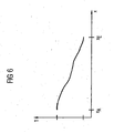
- FIG. 6 shows a possible temperature profile T over the locations x of the cooling section 4, wherein the cooling section 4 by the beginning of the cooling section x A and the end of the cooling section x E is limited.
- a comparable image would result from applying a temperature history T over time.
- FIG. 3 represents the model-predictive control of the cooling section closer.
- the cooling line control 12 preferably not individual valves 7a and 7b, collectively referred to as 7, driven, but from one or more valves 7 existing valve groups.
- the control region 14 can be divided into a plurality of subregions 14a and 14b, wherein preferably each subregion 14a or 14b is assigned a valve group.
- control range 14 Within the limits of the control range 14, the boundaries of which usually coincide with the limits of the cooling path, a distinction can be made with regard to the control between a main control range 15 and a trim control range 16.
- individual band points (13a, 13b) are tracked.
- a model-predictive algorithm is used to control and regulate the cooling section.
- actuators for N u time steps are determined in the future as a solution of a preferably quadratic optimization problem, wherein predictions are made with the model for N y time steps.
- N u may be 1 or even a natural number greater than 1. In the latter case, only the calculated actuator settings for the first time step are usually implemented. For the next time step, we recalculated taking into account current measured values or predicted values.
- N y must be chosen large enough to overcome the largest dead time available.
- the largest dead time results from the largest distance of a temperature measuring point and the position of the nearest upstream free control valve.
- a suitable, preferably linearized, strip temperature model is used.
- a model predictive control of the cooling section can also be based on the enthalpy curve in the cooling section.
- the enthalpy course over the location x or over time is comparable to the temperature course over the location (see also FIG. 6 ) or over time.
- the computing device 10 it is possible for the computing device 10 to have a cooling line control module 12, which in turn has a plurality of partial control modules 17a, 17b, which correspond to different control regions 14a and 14b.
- the control or regulation of the cooling section 4 according to the invention is independent of the cooling route layout and, because of the model-predictive control, also offers optimum control of the control limits at the control limits. Specifications can be weighted differently in terms of prioritization in a flexible way. Edge-masking can be integrated into the control method according to the invention.
- the inventive method can be designed such that the speed of the metal strip 6 can be controlled, which makes its use possible, for example, for heavy plate mills.
- a finishing train 3 can also be regulated according to the invention.
- interstand cooling devices are further possible actuators in a finishing line.
- a typical number of actuators for a cooling line are about 200 valves 7. This is a significantly higher number of actuators than for a typical finishing line 3.
- An overall control for a plurality of plant parts 1 to 5 can preferably be achieved as described below, for example for a finishing train 3 and a cooling section 4.
- the temperature model of the finishing train 3 and the temperature model of the cooling section 4 are concatenated.
- a preferably quadratic optimization problem with preferably linear secondary conditions is determined, by means of which a common control method is provided for both equipment parts 3 and 4.
- the optimization of the problem thus provides the settings for the interstitial cooling of the finishing train 3, the cooling line valves 7 of the cooling section 4 and speed of the metal strip 6, in particular for each next control step.
Landscapes
- Engineering & Computer Science (AREA)
- Mechanical Engineering (AREA)
- Control Of Metal Rolling (AREA)
- Control Of Heat Treatment Processes (AREA)
- Heat Treatment Of Strip Materials And Filament Materials (AREA)
Claims (16)
- Procédé pour se rendre maître et/ou régler la température d'un feuillard ( 5 ) métallique dans une installation de la sidérurgie, notamment dans une zone ( 4 ) de refroidissement, qui est montée en aval d'un train ( 2, 3 ) de laminoir pour laminer du feuillard ( 6 ) à chaud métallique dans lequel, pour déterminer des signaux de réglage, on compare une courbe de température de consigne à une courbe de température réelle, dans lequel on suit le trajet de points ( 13a, 13b ) du feuillard, on détermine une courbe de température pour divers points ( 13a, 13b ) du feuillard et, en tenant compte de contraintes secondaires, on forme au moins une fonction performance pour plusieurs organes de réglage dans une partie ( 14 ) de régulation de la section ( 4 ) de refroidissement, la partie ( 14 ) de régulation de la zone ( 4 ) de refroidissement étant subdivisée en plusieurs sous-parties ( 14a, 14b ) qui se succèdent dans la direction de passage du feuillard ( 6 ) métallique et un groupe de respectivement plusieurs soupapes ( 7 ) étant associé à chaque sous partie ( 14a, 14b ), caractérisé en ce que l'on minimise ou maximise la fonction performance en résolvant un problème d'optimisation, en ce que, dans le cadre de la résolution du problème d'optimisation, on conçoit les groupes de respectivement plusieurs soupapes ( 7 ) de la zone ( 4 ) de refroidissement comme organes de réglage et ce que pour chaque organe de réglage de ce genre, on calcule une valeur de réglage qui, dans le cadre de la commande des soupapes ( 7 ), est subdivisé suivant une heuristique de commutation entre les diverses soupapes des groupes respectifs et en ce que l'on commande groupe par groupe les soupapes ( 7 ) dans le cadre de leur commande.
- Procédé suivant la revendication 1, caractérisé en ce que l'on résout un problème d'optimisation quadratique.
- Procédé suivant l'une des revendications précédentes, caractérisé en ce que l'on détermine la courbe de température réelle et/ou la courbe de température de consigne du feuillard ( 6 ) métallique en s'aidant d'au moins un modèle.
- Procédé suivant l'une des revendications précédentes, caractérisé en ce que l'on détermine la courbe d'enthalpie réelle et/ou la courbe d'enthalpie de consigne en s'aidant d'au moins un modèle.
- Procédé suivant la revendication 3 ou 4, caractérisé en ce que l'on adapte le modèle en ligne.
- Procédé suivant l'une des revendications 2 à 5, caractérisé en ce que l'on minimise ou l'on maximise la fonction de performance en résolvant le problème d'optimisation au moyen d'un calcul préalable.
- Procédé suivant l'une des revendications précédentes, caractérisé en ce que l'on minimise ou maximise par itération la fonction performance de préférence en ligne en résolvant le problème d'optimisation.
- Procédé suivant la revendication 7, caractérisé en ce que l'on effectue dans chaque cadence de temps un stade d'itération dans lequel, à partir d'une solution du problème d'optimisation associée à une cadence de temps instantanée, on entre au moins un signal de réglage dans l'installation.
- Procédé suivant la revendication 8, caractérisé en ce que l'on tient compte pour une cadence de temps venant ensuite d'autres valeurs de mesure dans la solution du problème d'optimisation.
- Procédé suivant la revendication 9, caractérisé en ce que l'on forme un circuit de régulation fermé.
- Procédé suivant l'une des revendications précédentes, caractérisé en ce que l'on résout le problème d'optimisation avec des contraintes linéaires.
- Procédé suivant l'une des revendications précédentes, caractérisé en ce que l'on commande et/ou régule la température du feuillard ( 5 ) métallique dans plusieurs parties ( 1 à 5 ) de l'installation de la sidérurgie, notamment dans le train ( 3 ) finisseur et dans une zone ( 4 ) de refroidissement en aval de celui-ci.
- Produit de programme informatique comprenant un moyen de code programme propre à effectuer les stades d'un procédé suivant l'une des revendications précédentes lorsque le produit de programme informatique est réalisé sur un dispositif à ordinateur.
- Dispositif ( 10 ) à ordinateur pour la mise en oeuvre du procédé suivant l'une des revendications 1 à 12, dans lequel le dispositif ( 10 ) à ordinateur influe directement et/ou indirectement sur la température du feuillard ( 6 ) métallique, caractérisé en ce que le dispositif à ordinateur est programmé par un produit de programme informatique suivant la revendication 15.
- Dispositif ( 10 ) à ordinateur suivant la revendication 14, caractérisé en ce qu'il comporte un moniteur ( 11 ) de zone de refroidissement, un module de calcul ( 20 ) à l'avance, un module d'adaptation ( 18 ) et un module de régulation ( 12 ) de la zone de refroidissement.
- Dispositif ( 10 ) à ordinateur suivant la revendication 14 ou 15, caractérisé en ce qu'il comporte plusieurs modules ( 17a, 17b ) de régulation d'organes de réglage ( 7 ) et/ou d'un ou de plusieurs domaines ( 14a, 14b ) de régulation comprenant des organes de réglage.
Applications Claiming Priority (5)
| Application Number | Priority Date | Filing Date | Title |
|---|---|---|---|
| DE10308222 | 2003-02-25 | ||
| DE10308222 | 2003-02-25 | ||
| DE2003121792 DE10321792A1 (de) | 2003-05-14 | 2003-05-14 | Verfahren zur Regelung der Temperatur eines Metallbandes, insbesondere in einer Kühlstrecke |
| DE10321792 | 2003-05-14 | ||
| PCT/EP2004/001365 WO2004076085A2 (fr) | 2003-02-25 | 2004-02-13 | Procede de regulation de la temperature d'une bande metallique, en particulier dans un parcours de refroidissement |
Publications (3)
| Publication Number | Publication Date |
|---|---|
| EP1596999A2 EP1596999A2 (fr) | 2005-11-23 |
| EP1596999B1 EP1596999B1 (fr) | 2006-12-20 |
| EP1596999B2 true EP1596999B2 (fr) | 2011-05-25 |
Family
ID=32928839
Family Applications (1)
| Application Number | Title | Priority Date | Filing Date |
|---|---|---|---|
| EP04710798A Expired - Lifetime EP1596999B2 (fr) | 2003-02-25 | 2004-02-13 | Procede de regulation de la temperature d'une bande metallique, en particulier dans un parcours de refroidissement |
Country Status (7)
| Country | Link |
|---|---|
| US (1) | US7251971B2 (fr) |
| EP (1) | EP1596999B2 (fr) |
| JP (1) | JP2006518669A (fr) |
| AT (1) | ATE348671T1 (fr) |
| DE (1) | DE502004002370D1 (fr) |
| NO (1) | NO20054189L (fr) |
| WO (1) | WO2004076085A2 (fr) |
Families Citing this family (18)
| Publication number | Priority date | Publication date | Assignee | Title |
|---|---|---|---|---|
| KR100847974B1 (ko) * | 2004-10-14 | 2008-07-22 | 도시바 미쓰비시덴키 산교시스템 가부시키가이샤 | 압연, 단조 또는 교정 라인의 재질 제어 방법 및 그 장치 |
| DE102007007560A1 (de) * | 2007-02-15 | 2008-08-21 | Siemens Ag | Verfahren zur Unterstützung einer wenigstens teilweise manuellen Steuerung einer Metallbearbeitungsstraße |
| DE102008011303B4 (de) * | 2008-02-27 | 2013-06-06 | Siemens Aktiengesellschaft | Betriebsverfahren für eine Kühlstrecke zum Kühlen eines Walzguts mit von der Temperatur losgelöster Kühlung auf einen Endenthalpiewert |
| KR101285990B1 (ko) * | 2008-11-19 | 2013-07-15 | 도시바 미쓰비시덴키 산교시스템 가부시키가이샤 | 제어 장치 |
| EP2301685A1 (fr) * | 2009-09-23 | 2011-03-30 | Siemens Aktiengesellschaft | Procédé de commande pour une installation de traitement d'un produit de laminage étendu en longueur |
| CN102069095B (zh) * | 2009-11-20 | 2014-05-21 | 浙江汇高机电科技有限公司 | 一种基于统计学习的精轧终轧温度预测和控制方法 |
| EP2540404A1 (fr) * | 2011-06-27 | 2013-01-02 | Siemens Aktiengesellschaft | Procédé de commande pour un laminoir à bandes à chaud |
| DE102013225579A1 (de) | 2013-05-22 | 2014-11-27 | Sms Siemag Ag | Vorrichtung und Verfahren zur Steuerung und/oder Regelung eines Glüh- oder Wärmebehandlungsofens einer Metallmaterial bearbeitenden Fertigungsstraße |
| CN104043660B (zh) * | 2013-09-26 | 2015-09-30 | 北大方正集团有限公司 | 一种非调质钢的生产工艺 |
| EP2898963A1 (fr) | 2014-01-28 | 2015-07-29 | Siemens Aktiengesellschaft | Section de refroidissement avec refroidissement double à une valeur de consigne respective |
| CN105689407B (zh) * | 2016-01-20 | 2019-03-19 | 北京首钢股份有限公司 | 一种提高厚规格带钢超快冷后温度控制精度的方法 |
| EP3495056B1 (fr) * | 2017-12-11 | 2020-09-16 | Primetals Technologies Austria GmbH | Commande améliorée de la gestion de l'eau d'un circuit de refroidissement |
| JP7058182B2 (ja) * | 2018-06-08 | 2022-04-21 | 株式会社日立製作所 | 目標温度履歴作成装置、目標温度履歴作成方法およびプログラム |
| DE102018220382A1 (de) * | 2018-11-28 | 2020-05-28 | Sms Group Gmbh | Verfahren zur Herstellung eines metallischen Bandes |
| DE102019104419A1 (de) | 2019-02-21 | 2020-08-27 | Sms Group Gmbh | Verfahren zur Einstellung verschiedener Kühlverläufe von Walzgut über der Bandbreite einer Kühlstrecke in einer Warmband- oder Grobblech-Straße |
| EP3825789A1 (fr) | 2019-11-20 | 2021-05-26 | Primetals Technologies Germany GmbH | Télécommande d'une installation de fabrication et/ou de traitement d'un produit de laminage métallique |
| CN113601806A (zh) * | 2021-06-29 | 2021-11-05 | 无锡有孚精工科技有限公司 | 一种模具生产用气液冷却装置、系统及方法 |
| EP4124398B1 (fr) * | 2021-07-27 | 2024-04-10 | Primetals Technologies Austria GmbH | Procédé de détermination des propriétés mécaniques d'un produit laminé a l'aide d'un modèle hybride |
Citations (2)
| Publication number | Priority date | Publication date | Assignee | Title |
|---|---|---|---|---|
| EP0997203A1 (fr) † | 1998-10-31 | 2000-05-03 | Sms Schloemann-Siemag Aktiengesellschaft | Procédé et système pour contrôler des lignes de refroidissement |
| DE19963186A1 (de) † | 1999-12-27 | 2001-07-12 | Siemens Ag | Verfahren zur Steuerung und/oder Regelung der Kühlstrecke einer Warmbandstrasse zum Walzen von Metallband und zugehörige Vorrichtung |
Family Cites Families (9)
| Publication number | Priority date | Publication date | Assignee | Title |
|---|---|---|---|---|
| JPS58221606A (ja) * | 1982-06-18 | 1983-12-23 | Sumitomo Metal Ind Ltd | 鋼帯の冷却制御方法 |
| JPH02169119A (ja) | 1988-12-22 | 1990-06-29 | Toshiba Corp | 板平坦度制御方法 |
| US5691921A (en) * | 1996-01-05 | 1997-11-25 | Xerox Corporation | Thermal sensors arrays useful for motion tracking by thermal gradient detection |
| JPH09285810A (ja) | 1996-04-25 | 1997-11-04 | Kawasaki Steel Corp | 形状の良好なh形鋼の製造方法 |
| AT408623B (de) * | 1996-10-30 | 2002-01-25 | Voest Alpine Ind Anlagen | Verfahren zur überwachung und steuerung der qualität von walzprodukten aus warmwalzprozessen |
| DE19717615A1 (de) | 1997-04-25 | 1998-10-29 | Siemens Ag | Verfahren und Einrichtung zur Kühlung von Metallen in einem Hüttenwerk |
| JP2000167615A (ja) * | 1998-12-03 | 2000-06-20 | Toshiba Corp | 巻取温度制御方法及び制御装置 |
| EP1014239B1 (fr) | 1998-12-16 | 2003-06-04 | VOEST-ALPINE INDUSTRIEANLAGENBAU GESELLSCHAFT m.b.H. | Procédé de calcul d' un patron de réduction |
| DE10203787A1 (de) * | 2002-01-31 | 2003-08-14 | Siemens Ag | Verfahren zur Regelung eines industriellen Prozesses |
-
2004
- 2004-02-13 AT AT04710798T patent/ATE348671T1/de active
- 2004-02-13 JP JP2006501836A patent/JP2006518669A/ja active Pending
- 2004-02-13 US US10/545,701 patent/US7251971B2/en not_active Expired - Fee Related
- 2004-02-13 EP EP04710798A patent/EP1596999B2/fr not_active Expired - Lifetime
- 2004-02-13 WO PCT/EP2004/001365 patent/WO2004076085A2/fr not_active Ceased
- 2004-02-13 DE DE502004002370T patent/DE502004002370D1/de not_active Expired - Lifetime
-
2005
- 2005-09-09 NO NO20054189A patent/NO20054189L/no not_active Application Discontinuation
Patent Citations (2)
| Publication number | Priority date | Publication date | Assignee | Title |
|---|---|---|---|---|
| EP0997203A1 (fr) † | 1998-10-31 | 2000-05-03 | Sms Schloemann-Siemag Aktiengesellschaft | Procédé et système pour contrôler des lignes de refroidissement |
| DE19963186A1 (de) † | 1999-12-27 | 2001-07-12 | Siemens Ag | Verfahren zur Steuerung und/oder Regelung der Kühlstrecke einer Warmbandstrasse zum Walzen von Metallband und zugehörige Vorrichtung |
Non-Patent Citations (4)
| Title |
|---|
| "Einführung in die Regelungs-technik", 1986, CARL HANSER VERLAGE MÜNCHEN WIEN, article PROF.DIPL.-ING. HEINZ MANN UND PROF.DR.-ING. HORST SCHIFFELGEN, pages: 56,57,76 - ,77,168, † |
| "HÜTTE", 1989, INTERDRUCK, LEIPZICH, ISBN: 3-540-19077-5, article H. CZICHOS: "Springer-Verlag Berlin Heidelberg 1989", pages: I2,I3,I4 - I52,I53 † |
| LEITHOFF M.D.; RICHARD DAHM J.: "Model reference control of runout table cooling at LTV", IRON AND STEEL ENGINEER, August 1989 (1989-08-01), PITTSBURGH, pages 31 - 35, XP000069320 † |
| SATYANARAYANA A.; BISWAS S.K.; CHEN J.S.: "Control system design for accelerated cooling process for optimized temperature-time tracking.", MANUFACTURING SCIENCE AND ENGINEERING, vol. 2, 1994, pages 663 - 674 † |
Also Published As
| Publication number | Publication date |
|---|---|
| WO2004076085A2 (fr) | 2004-09-10 |
| US7251971B2 (en) | 2007-08-07 |
| US20060225474A1 (en) | 2006-10-12 |
| EP1596999B1 (fr) | 2006-12-20 |
| WO2004076085A3 (fr) | 2004-10-21 |
| DE502004002370D1 (de) | 2007-02-01 |
| ATE348671T1 (de) | 2007-01-15 |
| JP2006518669A (ja) | 2006-08-17 |
| EP1596999A2 (fr) | 2005-11-23 |
| NO20054189L (no) | 2005-09-09 |
Similar Documents
| Publication | Publication Date | Title |
|---|---|---|
| EP1596999B1 (fr) | Procede de regulation de la temperature d'une bande metallique, en particulier dans un parcours de refroidissement | |
| EP1624982B2 (fr) | Procede de regulation de la temperature d'une bande metallique, en particulier dans un train finisseur pour le laminage a chaud de bandes metalliques | |
| EP1444059B1 (fr) | Procede pour commander un train finisseur monte en amont d'une section de refroidissement et concu pour laminer des feuillards metalliques a chaud | |
| EP2566633B1 (fr) | Procédé pour faire fonctionner un train finisseur avec prédiction de la vitesse de commande | |
| EP2456897B1 (fr) | Procédé de commande et/ou de réglage d'un four à induction pour un laminoir, dispositif de commande et/ou de réglage pour un laminoir et laminoir destiné à la fabrication d'un produit de laminage | |
| EP2697001B1 (fr) | Procédé de commande pour train de laminage | |
| AT414316B (de) | Verfahren und einrichtung zur steuerung einer hüttentechnischen anlage | |
| EP2697002B1 (fr) | Procédé de commande pour train de laminoir | |
| EP1567681A1 (fr) | Procede de commande ou de regulation de processus d'une installation de formage, de refroidissement et/ou de traitement thermique de metal | |
| EP3642372B1 (fr) | Procédé permettant de faire fonctionner un four de recuit | |
| EP3720623B1 (fr) | Système d'étirement, de courbure et de redressement et son procédé d'actionnement | |
| EP2480351B1 (fr) | Procédé de commande pour une installation de traitement d'un matériau laminé allongé | |
| EP4247574A1 (fr) | Procédé de correction des propriétés d'une bande laminée à chaud ayant une composition chimique spécifique dans un laminoir à chaud | |
| EP4101553B1 (fr) | Refroidissement d'un produit laminé en amont d'un train finisseur d'un laminoir à chaud | |
| EP1014239B1 (fr) | Procédé de calcul d' un patron de réduction | |
| WO2023186585A1 (fr) | Procédé de fabrication d'un produit métallique | |
| DE10321791A1 (de) | Verfahren zur Regelung der Temperatur eines Metallbandes, insbesondere in einer Fertigstraße zum Walzen von Metall-Warmband | |
| DE10321792A1 (de) | Verfahren zur Regelung der Temperatur eines Metallbandes, insbesondere in einer Kühlstrecke | |
| EP4122613A1 (fr) | Procédé de fabrication d'une bande métallique | |
| EP4311606B1 (fr) | Procédé de régulation d'un train de laminage ainsi que train de laminage | |
| DE102022212627A1 (de) | Verfahren zum Herstellen eines Stahlbandes aus einem Vorprodukt, bei dem die Sollwerte über die Länge eines einzelnen Stahlbandes und / oder zeitlich in Bezug auf eine einzelne Produktionsanlage einer Walzstraße variabel vorgegeben werden | |
| EP3660173B1 (fr) | Procédé de fabrication d'une bande métallique | |
| WO2013160166A1 (fr) | Adaptation des propriétés d'une bande par refroidissement d'une ébauche de bande en fonction de sa largeur | |
| DE102019203088A1 (de) | Verfahren zur Herstellung eines metallischen Bandes oder Blechs |
Legal Events
| Date | Code | Title | Description |
|---|---|---|---|
| PUAI | Public reference made under article 153(3) epc to a published international application that has entered the european phase |
Free format text: ORIGINAL CODE: 0009012 |
|
| 17P | Request for examination filed |
Effective date: 20050720 |
|
| AK | Designated contracting states |
Kind code of ref document: A2 Designated state(s): AT BE BG CH CY CZ DE DK EE ES FI FR GB GR HU IE IT LI LU MC NL PT RO SE SI SK TR |
|
| AX | Request for extension of the european patent |
Extension state: AL LT LV MK |
|
| DAX | Request for extension of the european patent (deleted) | ||
| GRAP | Despatch of communication of intention to grant a patent |
Free format text: ORIGINAL CODE: EPIDOSNIGR1 |
|
| GRAS | Grant fee paid |
Free format text: ORIGINAL CODE: EPIDOSNIGR3 |
|
| GRAA | (expected) grant |
Free format text: ORIGINAL CODE: 0009210 |
|
| AK | Designated contracting states |
Kind code of ref document: B1 Designated state(s): AT BE BG CH CY CZ DE DK EE ES FI FR GB GR HU IE IT LI LU MC NL PT RO SE SI SK TR |
|
| PG25 | Lapsed in a contracting state [announced via postgrant information from national office to epo] |
Ref country code: IE Free format text: LAPSE BECAUSE OF FAILURE TO SUBMIT A TRANSLATION OF THE DESCRIPTION OR TO PAY THE FEE WITHIN THE PRESCRIBED TIME-LIMIT Effective date: 20061220 Ref country code: RO Free format text: LAPSE BECAUSE OF FAILURE TO SUBMIT A TRANSLATION OF THE DESCRIPTION OR TO PAY THE FEE WITHIN THE PRESCRIBED TIME-LIMIT Effective date: 20061220 Ref country code: SI Free format text: LAPSE BECAUSE OF FAILURE TO SUBMIT A TRANSLATION OF THE DESCRIPTION OR TO PAY THE FEE WITHIN THE PRESCRIBED TIME-LIMIT Effective date: 20061220 Ref country code: SK Free format text: LAPSE BECAUSE OF FAILURE TO SUBMIT A TRANSLATION OF THE DESCRIPTION OR TO PAY THE FEE WITHIN THE PRESCRIBED TIME-LIMIT Effective date: 20061220 Ref country code: NL Free format text: LAPSE BECAUSE OF FAILURE TO SUBMIT A TRANSLATION OF THE DESCRIPTION OR TO PAY THE FEE WITHIN THE PRESCRIBED TIME-LIMIT Effective date: 20061220 Ref country code: CZ Free format text: LAPSE BECAUSE OF FAILURE TO SUBMIT A TRANSLATION OF THE DESCRIPTION OR TO PAY THE FEE WITHIN THE PRESCRIBED TIME-LIMIT Effective date: 20061220 Ref country code: DK Free format text: LAPSE BECAUSE OF FAILURE TO SUBMIT A TRANSLATION OF THE DESCRIPTION OR TO PAY THE FEE WITHIN THE PRESCRIBED TIME-LIMIT Effective date: 20061220 |
|
| REG | Reference to a national code |
Ref country code: GB Ref legal event code: FG4D Free format text: NOT ENGLISH |
|
| REG | Reference to a national code |
Ref country code: CH Ref legal event code: EP |
|
| REF | Corresponds to: |
Ref document number: 502004002370 Country of ref document: DE Date of ref document: 20070201 Kind code of ref document: P |
|
| REG | Reference to a national code |
Ref country code: IE Ref legal event code: FG4D Free format text: LANGUAGE OF EP DOCUMENT: GERMAN |
|
| PG25 | Lapsed in a contracting state [announced via postgrant information from national office to epo] |
Ref country code: MC Free format text: LAPSE BECAUSE OF NON-PAYMENT OF DUE FEES Effective date: 20070228 |
|
| PG25 | Lapsed in a contracting state [announced via postgrant information from national office to epo] |
Ref country code: BG Free format text: LAPSE BECAUSE OF FAILURE TO SUBMIT A TRANSLATION OF THE DESCRIPTION OR TO PAY THE FEE WITHIN THE PRESCRIBED TIME-LIMIT Effective date: 20070320 |
|
| REG | Reference to a national code |
Ref country code: SE Ref legal event code: TRGR |
|
| PG25 | Lapsed in a contracting state [announced via postgrant information from national office to epo] |
Ref country code: ES Free format text: LAPSE BECAUSE OF FAILURE TO SUBMIT A TRANSLATION OF THE DESCRIPTION OR TO PAY THE FEE WITHIN THE PRESCRIBED TIME-LIMIT Effective date: 20070331 |
|
| PG25 | Lapsed in a contracting state [announced via postgrant information from national office to epo] |
Ref country code: PT Free format text: LAPSE BECAUSE OF FAILURE TO SUBMIT A TRANSLATION OF THE DESCRIPTION OR TO PAY THE FEE WITHIN THE PRESCRIBED TIME-LIMIT Effective date: 20070424 |
|
| NLV1 | Nl: lapsed or annulled due to failure to fulfill the requirements of art. 29p and 29m of the patents act | ||
| ET | Fr: translation filed | ||
| GBV | Gb: ep patent (uk) treated as always having been void in accordance with gb section 77(7)/1977 [no translation filed] |
Effective date: 20061220 |
|
| PLBI | Opposition filed |
Free format text: ORIGINAL CODE: 0009260 |
|
| PLAX | Notice of opposition and request to file observation + time limit sent |
Free format text: ORIGINAL CODE: EPIDOSNOBS2 |
|
| 26 | Opposition filed |
Opponent name: SMS DEMAG AG Effective date: 20070920 |
|
| PG25 | Lapsed in a contracting state [announced via postgrant information from national office to epo] |
Ref country code: GB Free format text: LAPSE BECAUSE OF FAILURE TO SUBMIT A TRANSLATION OF THE DESCRIPTION OR TO PAY THE FEE WITHIN THE PRESCRIBED TIME-LIMIT Effective date: 20061220 |
|
| PLBB | Reply of patent proprietor to notice(s) of opposition received |
Free format text: ORIGINAL CODE: EPIDOSNOBS3 |
|
| PG25 | Lapsed in a contracting state [announced via postgrant information from national office to epo] |
Ref country code: GR Free format text: LAPSE BECAUSE OF FAILURE TO SUBMIT A TRANSLATION OF THE DESCRIPTION OR TO PAY THE FEE WITHIN THE PRESCRIBED TIME-LIMIT Effective date: 20070321 |
|
| REG | Reference to a national code |
Ref country code: CH Ref legal event code: PL |
|
| PG25 | Lapsed in a contracting state [announced via postgrant information from national office to epo] |
Ref country code: LI Free format text: LAPSE BECAUSE OF NON-PAYMENT OF DUE FEES Effective date: 20080229 Ref country code: CH Free format text: LAPSE BECAUSE OF NON-PAYMENT OF DUE FEES Effective date: 20080229 |
|
| PG25 | Lapsed in a contracting state [announced via postgrant information from national office to epo] |
Ref country code: EE Free format text: LAPSE BECAUSE OF FAILURE TO SUBMIT A TRANSLATION OF THE DESCRIPTION OR TO PAY THE FEE WITHIN THE PRESCRIBED TIME-LIMIT Effective date: 20061220 |
|
| APBM | Appeal reference recorded |
Free format text: ORIGINAL CODE: EPIDOSNREFNO |
|
| APBP | Date of receipt of notice of appeal recorded |
Free format text: ORIGINAL CODE: EPIDOSNNOA2O |
|
| APAH | Appeal reference modified |
Free format text: ORIGINAL CODE: EPIDOSCREFNO |
|
| APBQ | Date of receipt of statement of grounds of appeal recorded |
Free format text: ORIGINAL CODE: EPIDOSNNOA3O |
|
| PG25 | Lapsed in a contracting state [announced via postgrant information from national office to epo] |
Ref country code: LU Free format text: LAPSE BECAUSE OF NON-PAYMENT OF DUE FEES Effective date: 20070213 Ref country code: CY Free format text: LAPSE BECAUSE OF FAILURE TO SUBMIT A TRANSLATION OF THE DESCRIPTION OR TO PAY THE FEE WITHIN THE PRESCRIBED TIME-LIMIT Effective date: 20061220 |
|
| PG25 | Lapsed in a contracting state [announced via postgrant information from national office to epo] |
Ref country code: HU Free format text: LAPSE BECAUSE OF FAILURE TO SUBMIT A TRANSLATION OF THE DESCRIPTION OR TO PAY THE FEE WITHIN THE PRESCRIBED TIME-LIMIT Effective date: 20070621 Ref country code: TR Free format text: LAPSE BECAUSE OF FAILURE TO SUBMIT A TRANSLATION OF THE DESCRIPTION OR TO PAY THE FEE WITHIN THE PRESCRIBED TIME-LIMIT Effective date: 20061220 |
|
| APBU | Appeal procedure closed |
Free format text: ORIGINAL CODE: EPIDOSNNOA9O |
|
| PG25 | Lapsed in a contracting state [announced via postgrant information from national office to epo] |
Ref country code: IT Free format text: LAPSE BECAUSE OF NON-PAYMENT OF DUE FEES Effective date: 20100213 |
|
| PUAH | Patent maintained in amended form |
Free format text: ORIGINAL CODE: 0009272 |
|
| STAA | Information on the status of an ep patent application or granted ep patent |
Free format text: STATUS: PATENT MAINTAINED AS AMENDED |
|
| 27A | Patent maintained in amended form |
Effective date: 20110525 |
|
| AK | Designated contracting states |
Kind code of ref document: B2 Designated state(s): AT BE BG CH CY CZ DE DK EE ES FI FR GB GR HU IE IT LI LU MC NL PT RO SE SI SK TR |
|
| REG | Reference to a national code |
Ref country code: SE Ref legal event code: RPEO |
|
| REG | Reference to a national code |
Ref country code: DE Ref legal event code: R102 Ref document number: 502004002370 Country of ref document: DE Effective date: 20110525 |
|
| PGFP | Annual fee paid to national office [announced via postgrant information from national office to epo] |
Ref country code: FI Payment date: 20130213 Year of fee payment: 10 |
|
| PGFP | Annual fee paid to national office [announced via postgrant information from national office to epo] |
Ref country code: AT Payment date: 20130108 Year of fee payment: 10 |
|
| PGFP | Annual fee paid to national office [announced via postgrant information from national office to epo] |
Ref country code: BE Payment date: 20130312 Year of fee payment: 10 |
|
| BERE | Be: lapsed |
Owner name: SIEMENS A.G. Effective date: 20140228 |
|
| REG | Reference to a national code |
Ref country code: AT Ref legal event code: MM01 Ref document number: 348671 Country of ref document: AT Kind code of ref document: T Effective date: 20140213 |
|
| PG25 | Lapsed in a contracting state [announced via postgrant information from national office to epo] |
Ref country code: FI Free format text: LAPSE BECAUSE OF NON-PAYMENT OF DUE FEES Effective date: 20140213 |
|
| PG25 | Lapsed in a contracting state [announced via postgrant information from national office to epo] |
Ref country code: AT Free format text: LAPSE BECAUSE OF NON-PAYMENT OF DUE FEES Effective date: 20140213 |
|
| PG25 | Lapsed in a contracting state [announced via postgrant information from national office to epo] |
Ref country code: BE Free format text: LAPSE BECAUSE OF NON-PAYMENT OF DUE FEES Effective date: 20140228 |
|
| REG | Reference to a national code |
Ref country code: FR Ref legal event code: PLFP Year of fee payment: 12 |
|
| REG | Reference to a national code |
Ref country code: DE Ref legal event code: R081 Ref document number: 502004002370 Country of ref document: DE Owner name: PRIMETALS TECHNOLOGIES GERMANY GMBH, DE Free format text: FORMER OWNER: SIEMENS AKTIENGESELLSCHAFT, 80333 MUENCHEN, DE |
|
| REG | Reference to a national code |
Ref country code: FR Ref legal event code: TP Owner name: PRIMETALS TECHNOLOGIES GERMANY GMBH, DE Effective date: 20151105 |
|
| REG | Reference to a national code |
Ref country code: FR Ref legal event code: PLFP Year of fee payment: 13 |
|
| PGFP | Annual fee paid to national office [announced via postgrant information from national office to epo] |
Ref country code: FR Payment date: 20160218 Year of fee payment: 13 Ref country code: SE Payment date: 20160217 Year of fee payment: 13 |
|
| REG | Reference to a national code |
Ref country code: SE Ref legal event code: EUG |
|
| PG25 | Lapsed in a contracting state [announced via postgrant information from national office to epo] |
Ref country code: SE Free format text: LAPSE BECAUSE OF NON-PAYMENT OF DUE FEES Effective date: 20170214 |
|
| REG | Reference to a national code |
Ref country code: FR Ref legal event code: ST Effective date: 20171031 |
|
| PG25 | Lapsed in a contracting state [announced via postgrant information from national office to epo] |
Ref country code: FR Free format text: LAPSE BECAUSE OF NON-PAYMENT OF DUE FEES Effective date: 20170228 |
|
| REG | Reference to a national code |
Ref country code: DE Ref legal event code: R081 Ref document number: 502004002370 Country of ref document: DE Owner name: PRIMETALS TECHNOLOGIES GERMANY GMBH, DE Free format text: FORMER OWNER: PRIMETALS TECHNOLOGIES GERMANY GMBH, 91052 ERLANGEN, DE |
|
| PGFP | Annual fee paid to national office [announced via postgrant information from national office to epo] |
Ref country code: IT Payment date: 20230223 Year of fee payment: 20 Ref country code: DE Payment date: 20230216 Year of fee payment: 20 |
|
| REG | Reference to a national code |
Ref country code: DE Ref legal event code: R071 Ref document number: 502004002370 Country of ref document: DE |