EP2697002B1 - Procédé de commande pour train de laminoir - Google Patents
Procédé de commande pour train de laminoir Download PDFInfo
- Publication number
- EP2697002B1 EP2697002B1 EP12719000.7A EP12719000A EP2697002B1 EP 2697002 B1 EP2697002 B1 EP 2697002B1 EP 12719000 A EP12719000 A EP 12719000A EP 2697002 B1 EP2697002 B1 EP 2697002B1
- Authority
- EP
- European Patent Office
- Prior art keywords
- strip
- rolling
- model
- predicted
- roll stand
- Prior art date
- Legal status (The legal status is an assumption and is not a legal conclusion. Google has not performed a legal analysis and makes no representation as to the accuracy of the status listed.)
- Active
Links
Images





Classifications
-
- B—PERFORMING OPERATIONS; TRANSPORTING
- B23—MACHINE TOOLS; METAL-WORKING NOT OTHERWISE PROVIDED FOR
- B23P—METAL-WORKING NOT OTHERWISE PROVIDED FOR; COMBINED OPERATIONS; UNIVERSAL MACHINE TOOLS
- B23P17/00—Metal-working operations, not covered by a single other subclass or another group in this subclass
-
- B—PERFORMING OPERATIONS; TRANSPORTING
- B21—MECHANICAL METAL-WORKING WITHOUT ESSENTIALLY REMOVING MATERIAL; PUNCHING METAL
- B21B—ROLLING OF METAL
- B21B37/00—Control devices or methods specially adapted for metal-rolling mills or the work produced thereby
- B21B37/58—Roll-force control; Roll-gap control
-
- B—PERFORMING OPERATIONS; TRANSPORTING
- B21—MECHANICAL METAL-WORKING WITHOUT ESSENTIALLY REMOVING MATERIAL; PUNCHING METAL
- B21B—ROLLING OF METAL
- B21B2261/00—Product parameters
- B21B2261/20—Temperature
- B21B2261/21—Temperature profile
-
- B—PERFORMING OPERATIONS; TRANSPORTING
- B21—MECHANICAL METAL-WORKING WITHOUT ESSENTIALLY REMOVING MATERIAL; PUNCHING METAL
- B21B—ROLLING OF METAL
- B21B2271/00—Mill stand parameters
- B21B2271/02—Roll gap, screw-down position, draft position
Definitions
- the present invention relates to a control method for a rolling line, wherein an actuator acting on a first stand of the rolling line is controlled during the rolling of strip sections taking into account at least one control parameter.
- the present invention further relates to a computer program comprising machine code which can be processed directly by a control computer for a rolling train and whose execution by the control computer causes the control computer to execute such a control method.
- the present invention further relates to a rolling table control computer programmed to execute such a control method in operation.
- the present invention further relates to a rolling train for rolling a belt, which comprises at least a first rolling mill and is equipped with such a control computer.
- Temperature variations across the width and length of the belt can lead to significant disturbances in the rolling operation. Due to the changing material hardness, there are variations in the rolling force, which in turn can lead to other skeletal reactions, which in turn have a change in the nip profile result. Examples of such framework reactions are roll flattening, roll deflection, and scaffold feathering. In addition, there is a change in the Walzenbombtechnik by the contact of the work rolls with the different warm band. This also has an influence on the geometry of the roll gap. If such changes in the roll gap profile are not taken into account, thickness, profile and flatness errors are the result.
- the AGC can not respond to variations in the temperature profile across the bandwidth.
- an asymmetry in the material strength for example, caused by a temperature wedge
- associated asymmetry in the framework reaction is not taken into account.
- a variation of the Walzenbombtechnik is not detectable or only with delay.
- the precontrol of the rolling stands of a multi-stand rolling train by means of the rolling force measurement in the first rolling stand of the rolling train is inherently not applicable to a single-storey street.
- this problem occurs in combined casting and rolling mills, where there are no or limited compensation for variations in temperature in the belt, so that temperature profiles (over the length and / or the bandwidth) until reaching the roll stand or the rolling stands have not compensated. Even with hot strip mill, it can lead to variations in temperature, for example, by the so-called skidmarks or uneven heating of the slab in the oven.
- a pure determination of the temperature behavior and possibly also the phase transformation of the strip sections is carried out with the aim of being able to suitably set a strip heating and / or a strip cooling.
- a utilization of the determined temperature in the context of the rolling process as such is in the DE 101 56 008 A1 not provided.
- a control method for a rolling train is known in which for strip sections of a strip in front of a first rolling stand of the rolling train in each case a temperature is determined which comprise the band sections.
- a temperature is determined which comprise the band sections.
- the object of the present invention is to provide ways by which the temperature profile of the belt during rolling of the belt can be taken into account in a particularly advantageous manner.
- the temperature profile of the strip should be taken into account in the profile adjustment of the roll gap.
- control method having the features of claim 1.
- Advantageous embodiments of the control method according to the invention are the subject of the dependent claims 2 to 11.
- the adjusting device for influencing the roll gap profile can be designed as required.
- a roll back bending and / or a roll displacement come into question.
- the adjusting device comprises a roll cooling device.
- the roll cooling device can be controlled in a spatially resolved manner, in particular in the bandwidth direction.
- control method with a second prognosis horizon is also carried out for a second rolling stand of the rolling train downstream of the first rolling stand.
- the strip sections in the first rolling stand are rolled from a first inlet thickness to a first outlet thickness and in the second rolling stand from a second inlet thickness to a second outlet thickness.
- first outlet thickness and / or the second inlet thickness are determined band-specific. As a result of this procedure, load redistribution between the first and the second roll stand can take place, in particular during ongoing rolling operation.
- the prognosis horizon for the second roll stand can be determined as required, but it must be dimensioned - analogous to the forecast horizon for the first roll stand - such that it corresponds to several strip sections, ie during the forecast horizon for the second rolling mill stand in the second rolling stand to be rolled.
- the second prognosis horizon is dimensioned such that during the second prognosis horizon several strip sections are rolled both in the first and in the second rolling stand.
- the forecast horizons for the first and the second roll stand can be dimensioned such that the difference of the forecast horizon corresponds to the time it takes for a strip section to pass from the first roll stand to the second roll stand.
- the forecast horizons can be placed, so to speak, at the same location in front of the first mill stand.
- the temperatures for the band sections may be sufficient to forecast the temperatures for the band sections as scalar quantities. Often, however, it is advantageous if the predicted by means of the tape model temperatures of the band sections in the bandwidth direction are spatially resolved. Preferably, in this case, the temperatures determined for the strip sections are already spatially resolved in the bandwidth direction.
- control computer causes the control computer to execute a control method according to the invention.
- control computer having the features of claim 13.
- the control computer is programmed such that it carries out an inventive control method during operation.
- a rolling train for rolling a belt which comprises at least a first roll stand, is equipped with a control computer programmed according to the invention.
- a rolling mill for rolling a strip 1 has a first rolling stand 2.
- the first rolling stand 2 may be the only rolling stand of the rolling train. Alternatively, further rolling mills may be present.
- the band 1 is usually a metal band, for example a steel, aluminum, magnesium or copper band. Other metals and metal alloys are also possible.
- the rolling train and thus also the first rolling stand 2 are controlled by a control computer 3.
- the control computer 3 is programmed with a computer program 4.
- the computer program 4 comprises machine code 5, which can be processed directly by the control computer 3.
- the processing of the machine code 5 by the control computer 3 - ie the operation of the control computer 3 - causes the control computer 3 at least one - possibly even more - performs the control method, which will be described below in connection with FIGS. 2 to 19 be explained in more detail.
- FIG. 2 takes the control computer 3 in a step S1 for band sections 6 of the belt 1 each a temperature T opposite. It is possible (and even common) for the temperatures T of the band sections 6 to be determined according to FIG FIG. 1 be detected by means of a temperature measuring device 7 metrologically. Alternatively, another determination - in particular calculation - done.
- the determination of the step S1 takes place for a location x which is located in front of the first rolling stand 2.
- the temperature T is thus characteristic of the respective temperature T of the respective band section 6 at a time at which the corresponding band section 6 is still in front of the first rolling stand 2.
- the control computer 3 implemented due to the programming with the computer program 4, inter alia, a band model 8.
- the band model 8 models by means of mathematical-physical equations at least the temperature behavior of the belt 1.
- a heat equation is achieved.
- the internal heat conduction within the band 1 as well as the interaction of the band 1 with its environment are taken into account, for example the interaction with cooling and heating devices, a scale scrubber, the contact with transport rollers.
- a phase transformation equation can also be achieved.
- An advantageous heat equation is for example in the DE 101 29 565 A1 or the same content US Pat. No. 6,860,950 B2 described.
- An advantageous phase conversion equation is for example in the EP 1 711 868 B1 or the same content US Pat. No. 7,865,341 B2 described.
- 8 other models can be included in the band model.
- the control computer 3 thus predicts the temperature of the belt sections 6 for the time of rolling of the respective belt section 6 in the first rolling stand 2 in a step S2 on the basis of the determined temperatures T.
- the predicted temperature is used to distinguish it from the determined temperature T. provided with the reference T '.
- the forecast is made with a forecast horizon PH1, hereinafter referred to as the first forecast horizon PH1.
- the first forecast horizon PH1 corresponds to the number of time steps by which the belt model 8 predicts the temperature T ', during each time step one strip section 6 in the first rolling stand 2 is rolled.
- the first forecast horizon PH1 comprises a single time step.
- a minimal forecast horizon PHmin is thus determined by the fact that the prediction of the temperature of the band sections 6 leads by a single time step.
- a single band section 6 is rolled, namely the immediately preceding band section 6.
- the first prognosis horizon PH1 is however dimensioned in this way in that during the first forecasting horizon PH1 in the first rolling stand 2 several band sections 6 are rolled, for example, five, eight, ten or more band sections. 6
- control computer 3 determines, using the predicted temperatures T 'of the belt sections 6, at least one control parameter P for rolling the respective belt section 6 in the first rolling stand 2.
- control computer 3 controls an actuating device 10.
- the control device 10 acts on the first rolling stand 2.
- the control of the adjusting device 10 takes place during the rolling of the respective band section 6, taking into account the control parameter P determined for the band section 6 currently to be rolled.
- a specific temperature T is determined for a specific band section 6, for example by measurement (step S1).
- the corresponding belt section 6 is tracked away during its transport through the mill train.
- the temperature T 'expected for the corresponding band section 6 is continuously included (step S2), the model-based temperature forecasting being at least one time step ahead of the location of the corresponding band section 6.
- the immediately preceding band section 6 is rolled-the control parameter P for the considered band section 6 is determined.
- the control parameter P is therefore known to the control computer 3 in good time, so that the control computer 3 can take into account the control parameter P in the control of the setting device 10 when the considered belt section 6 is rolled in the first rolling stand 2.
- the procedure of FIG. 2 is usually performed clocked, for example, with a time cycle between 0.1 second and 0.5 seconds, usually about 0.2 seconds to 0.3 seconds. With each time clock, the temperature T is determined for a new band section 6 and so the control computer 3 known. The temperature forecast is then model-based.
- the control computer 3 also requires the predicted temperatures T 'and possibly also other properties of other belt sections 6 and / or predicted properties of the first rolling stand 2. As far as the belt sections 6 to be rolled according to the considered belt section 6 are concerned, their temperatures and properties are known to the control computer 3 if they are within the first prognosis horizon PH1. For example, the control computer 3 is already aware of the expected temperatures T 'of the seven subsequent belt sections 6 at a first forecast horizon PH1 of eight belt sections 6 at the time at which a specific belt section 6 determines its temperature T.
- the predicted temperatures T 'of the eight belt sections 6 located in front of the first rolling mill 2 are known at all times. Therefore, they can be considered for the determination of the control parameter P for the strip section 6, which is rolled in the first stand 2 next.
- the temperatures and properties of the control computer 3 from the past are known.
- the first prognosis horizon PH1 is dimensioned such that several band sections 6 are rolled in the first rolling stand 2 during the first prognosis horizon PH1.
- the first prognosis horizon PH1 corresponds to eight band sections 6.
- this dimensioning is only illustrative, so is not limiting to forcibly eight band sections 6 to understand.
- step S2 is merely to mention that in the context of step S2 of FIG. 3 the step S2 with the first forecast horizon PH1 of a plurality of - purely exemplary eight - band sections 6 is executed.
- step S2 of FIG. 3 the corresponding temperatures T 'are predicted for all belt sections 6, which are up to eight belt sections 6 in front of the first rolling mill 2 at the time considered.
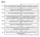
- Step S3 of FIG. 2 is in FIG. 3 implemented by steps S6 to S10.
- the adjusting device 10 is formed such that with her the profile of the roll gap - ie the distance of the work rolls 9 of the first stand 2 seen from each other across the width - can be adjusted.
- the adjusting device 10 may be designed for this purpose as a roller pushing device and / or as a roller bending device.
- the adjusting device 10 may comprise a roller cooling device 11, possibly alone, alternatively in addition to a roller pushing and / or roller bending device.
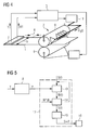
- the roll cooling device 11 can as shown in FIG FIG. 4 be controlled in particular in the bandwidth direction spatially resolved.
- step S6 a manipulated variable course S (t) for the actuator 10 attached.
- the manipulated variable course S (t) is set for the first prognosis horizon PH1 - ie the considered band section 6 and the seven band sections 6 following the band section 6 under consideration.
- the profile of the roll gap is influenced in accordance with the nature of the adjusting device 10.
- the thermal crowning of the work rolls 9 can be adjusted, for example, by the roll cooling device 11.
- the manipulated variable optimizer 12 is a software block implemented by the control computer 3. It includes, inter alia, a roll stand model 13.
- the roll stand model 13 models in particular the thermal crowning of the work rolls 9 and the wear of the work rolls 9, which results from the contact of the work rolls 9 with the strip 1.
- the roll stand model 13 further models the influence of the control variable course S (t) on the roll gap, for example the influence of the roll cooling device 11 on the thermal crowning.
- the rolling stand model 13 predicts in step S8 as output variable a temporal roll gap profile profile W (t).
- the rolling stand model 13 thus determines in step S8 for each lying within the first forecasting horizon PH1 band section 6, the roll gap profile W, that for the respective Band section 6 results.
- the roll stand model 13 determines the roll gap profile profile W (t) using the control variable curve S (t) supplied to it and the predicted temperatures T 'of the strip sections 6.
- the nip profile profile W (t) is determined according to FIG. 3 and 5 evaluated in an evaluator 14 and optimized by the evaluator 14 in step S9.
- a renewed call of the roll stand model 13 can take place after a modification of the scheduled manipulated variable profile S (t). This is in the FIG. 5 indicated by dashed lines.
- the determined roll gap profile profile W (t) is compared with a desired profile profile W * (t).
- the desired profile profile W * (t) can be constant. Regardless of whether the desired profile profile W * (t) is constant or not, the primary aim of the optimization is to ensure the flatness of the band 1. Subordinated should be rolled as far as possible a uniform profile as possible.
- the temperature detection is according to FIG. 4 coupled with a band thickness detection and / or a band profile detection.
- the desired profile W * for the respective band section 6 can be determined in a profile and flatness model on the basis of the detected strip thickness or the detected strip thickness profile.
- the optimized manipulated variable profile S (t) is determined according to FIG. 5 a selector 15 is supplied.
- the selector 15 selects in step S10 the current value of the optimized manipulated variable curve S (t), ie the value of the optimized manipulated variable curve S (t), which was determined for the strip section 6 to be rolled next.
- This value S corresponds to the control parameter P of the step S4 and is the actuator 10 in step S4 of FIG. 3 specified as a manipulated variable.
- the manipulated variable optimizer 12 in the context of FIG. 3 determined optimized control curve S (t) "forgets". However, the manipulated variable optimizer 12 preferably "remembers" the optimized manipulated variable profile S (t) and uses it for the matching band sections 6 as an applied manipulated variable curve S (t) for the next operating cycle, ie when the next strip section 6 is treated.
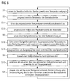
- FIG. 6 is a modification of FIG. 3 .
- FIG. 7 a modification of FIG. 5 , In the following, therefore, only the differences from these FIG will be discussed in more detail.
- step S11 the temperatures T 'predicted by the belt model 8 are fed to a rolling force model 16.
- step S12 the rolling forces F are predicted in step S12 using the predicted temperatures T 'for the respective belt sections 6.
- the rolling force model 16 thus determines, for each band section 6 to be rolled within the first prognosis horizon PH1, which rolling force F is required in order to roll the corresponding band section 6 from a first inlet thickness di1 to a desired first outlet thickness do1.
- the additional sizes required for this purpose such as the chemical composition of the strip 1, the first inlet thickness di1, the strip width b, the rolling speed v, inlet and outlet sides, etc., are likewise fed to the rolling force model 16.
- step S13 the manipulated variable optimizer 12 - as in step S7 of FIG. 3 also - the predicted temperatures T 'and the scheduled Control variable course S (t) supplied.
- the predicted rolling forces F are fed to the manipulated variable optimizer 12 in step S13.
- step S14 the manipulated variable optimizer 12 predicts in the context of its roll stand model 13 analogously to step S8 of FIG FIG. 3 for the band sections 6 to be rolled in the first rolling stand 2 in the first prognostic horizon PH1, the respective rolling gap profile W is additionally taken into account in the step S14 in the prognostication of the roll gap profile profile W (t).
- the band model 8 according to FIG. 9 are the steps S2, S11 and S12 of FIG. 6 replaced by steps S16 to S18.
- the band model 8 according to FIG. 9 a temperature model 17 and a material model 18.
- the temperatures T 'of the band sections 6 are predicted in step S16 - as previously in step S2 by the band model 8.
- a further material property is predicted by means of the material model 18, which is expected for the respective strip sections 6 to be rolled in the first rolling stand 2 during the first forecasting horizon PH1 during the rolling of the respective strip section 6 in the first rolling stand 2.
- the further material property is - of course - different from the temperature T ', but has an influence on the rolling force required for rolling the respective strip section 6.
- the further material property may be a phase transformation degree, a material consolidation, a recrystallization or act a microstructure.
- a unidirectional or bidirectional coupling between the temperature development and the development of the further material property can exist.
- the course of the temperature of the considered band section 6 during the first prediction horizon PH1 determined, then determines the determined temporal temperature profile of the material model 18 and finally determined on the basis of the material model 18, the further material property.
- step S17 the rolling force model 16 - in addition to the values and sizes mentioned in step S11 - are also supplied with the corresponding further material properties for the corresponding strip sections 6.
- step S18 the rolling force model 16 predicts the required rolling forces F with additional consideration of the further material properties as well.
- control computer 3 takes into account the procedure of the.
- the further material properties influence the predicted rolling forces F, this in turn on the nip profile W and this in turn on the optimized control variable course S (t) FIG. 8 and 9
- FIG. 10 is a possible embodiment of FIG. 2 in which, however, the steps S2 to S4 of FIG. 4 are replaced by steps S21 to S23.
- step S21 analogously to step S2, the temperature T 'of the corresponding band section 6 is predicted. Unlike step S2 of FIG. 2 is the predicted temperature T 'in the procedure according to FIG. 10 however, spatially resolved in the bandwidth direction.
- the first forecast horizon PH1 can be used in the embodiment of FIG. 10 be small. It may even correspond to the minimum forecast horizon PHmin. Alternatively, the first forecast horizon PH1 may be larger.
- a respective current material module M which is expected for the time, is predicted in determination blocks 19-separately for the operator side and the drive side-using the temperatures T 'predicted for the respective side of the first rolling stand 2 for the respective belt section 6 to which the corresponding band section 6 is rolled in the first rolling stand 2.
- the respective material module M is essentially characteristic for the strength or deformability of the corresponding band section 6 on the corresponding side of the first rolling stand 2.
- the adjusting device 10 is - at least within limits independently of each other - each an actuator 20 (for example, a hydraulic cylinder unit) controllable, by means of which the rolling force F and operating side on the work rolls 9 can be applied and so the roll gap can be influenced.
- the corresponding material modules M are preset in step S23 to the actuators 20 at the time when the corresponding strip section 6 in the first rolling stand 2 is rolled. They are therefore used at the appropriate time for the parameterization of the operator and the drive-side roll gap control.
- FIG. 12 Analogous to the addition of FIG. 6 and 7 through the design of the FIG. 8 and 9 can the design of the FIG. 10 and 11 according to the FIG. 12 and 13 be further developed.
- FIG. 12 are the steps S21 and S22 of FIG. 10 replaced by steps S26 and S27.
- the belt model 8 has the temperature model 17 and the material model 18.
- step S26 By means of the temperature model 17 is in step S26 - analogous to step S21 of FIG. 10 - The user-side and the drive-side temperature T 'of the corresponding band section 6 predicts.
- step S26 is further - analogous to step S16 of FIG. 8 -
- the further material property is according to FIG. 13 separately predicted for the drive side and the operating side of the first stand 2.
- the respective further material property is also supplied to the determination blocks 19.
- the determination blocks 19 therefore determine the respective material module M not only using the respective predicted temperatures T 'but also using the respective predicted further material properties.
- the temperatures T 'predicted for the band sections 6 may be determined as scalars, ie in each case only one value per band section 6. This is for one of the band sections 6 in FIG FIG. 14 indicated. In FIG. 14 the location of the corresponding band section 6 is shown for different times. There, the temperatures T 'predicted for the respective time are each symbolized by a black circle. In the case of a scalar prediction of the temperature T ', it is of course also sufficient to not (initially) determine the temperatures T' within the corresponding band section 6 in the bandwidth direction location-resolved. Of course, however, in the approach of 3 to 9 a spatially resolved determination of the temperature T and forecast the temperature T 'possible.
- the initial determination of the temperature T - that is, at the beginning of the first prognosis horizon PH1 - in the bandwidth direction, not spatially resolved. This may be possible, for example, if the band 1 initially has a uniform temperature T, but has a thickness wedge in the bandwidth direction and therefore cools faster on the thin side than on the thicker side. In general, however, the first-time determination of the temperature T of the band sections 6 in this case according to the dashed representation in the FIG. 11 and 13 spatially resolved in the bandwidth direction.
- the rolling train has a single rolling mill, that is, only the first rolling stand 2 is present.
- a single roll stand can be sufficient, in particular, if casting of the strip 1 takes place very close to the final dimensions, for example by means of rotating casting rolls. In many cases, however, several rolling stands are available. For example, a multi-stand finishing train typically has six or seven rolling stands.
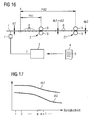
- the second rolling stand 21 is immediately downstream of the first rolling stand 2.
- the second run-in thickness di2 is identical to the first run-out thickness do1. Otherwise, the second inlet thickness di2 is smaller than the first outlet thickness do1.
- a prognosis horizon PH2 for the second rolling stand 21 - hereinafter called the second prognosis horizon PH2 - can be determined independently of the first prognosis horizon PH1.
- the second prognosis horizon PH2 is preferably dimensioned such that during the second prognosis horizon PH2 several band sections 6 are rolled both in the first and in the second rolling stand 2, 21.
- the second forecast horizon PH2 according to FIG. 16 be greater by that period of time, which requires a band section 6 to get from the first stand 2 to the second rolling mill 21.
- the first and the second prognosis horizon PH1, PH2 start in this case at the same location x in front of the first rolling stand 2.
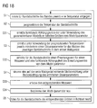
- FIG. 18 are - analogous to FIG. 2 -
- the steps S1 to S4 available.
- the steps S1 to S4 can according to the embodiments of FIGS. 3 to 17 complemented and designed.
- steps S31 to S35 are provided.
- one of the models used for determining the at least one control parameter P can be parameterized by means of a model parameter k.
- the band model 8 can be parameterized by means of the model parameter k.
- the rolling force model 16, the roll stand model 13, etc. could be parameterized by means of the model parameter k.
- step S31 according to FIG. 18 in real-time functional dependencies of the parameters determined directly or indirectly using the parameterizable model 8 of the model parameter k is determined.
- the quantities mentioned in this context are those variables which are needed directly or indirectly using the parameterizable model 8 for determining the at least one control parameter P.
- step S31 for example, functional dependencies of the required rolling forces F, the resulting thermal crowning of the work rolls 9, the material modules M, etc. can be determined.
- the step S31 since it is in addition to the steps S2 and S3, is executed in addition to the determination of the respective quantities themselves.
- step S32 using the parameters determined by means of the parameterizable model 8 - that is to say those variables which are calculated using the parameterizable model 8 in the context of the parameterization model 8 FIGS. 2 to 17 be determined anyway - for the band sections 6 in real time an expected value EW for a measured value MW determined. Furthermore, in step S32, a functional dependence of the expected value EW on the model parameter k is determined.
- the expected value EW can be, for example, the rolling force F with which the corresponding strip section 6 is expected to be rolled, a temperature or a tensile distribution in strip 1.
- the corresponding measured value MW is detected in real time by means of a corresponding measuring device 22 for the respective band section 6.
- the measuring device 22 can be arranged behind the first rolling stand 2, for example for a thickness, tensile or temperature detection (possibly spatially resolved in the bandwidth direction).
- the measuring device 22 may be arranged in front of the first rolling stand 2, for example for a temperature or tension detection (possibly spatially resolved in the bandwidth direction).
- the measuring device 22 - for example for a rolling force or attitude detection - be arranged on the first stand 2 itself.
- step S34 the model parameter k is redetermined based on the measured value MW, the associated expected value EW and the functional dependence of the expected value EW on the model parameter k, ie the corresponding model 8 is newly parameterized, ie the corresponding model 8 is adapted.
- the new, updated model parameter k is used for calculations made by means of the parameterizable model 8 after adapting the parameterizable model 8.
- step S35 the control computer 3 performs the corresponding quantities in real time for the band sections 6 whose temperatures T have already been determined and whose expected temperatures T 'and the corresponding control parameters P have already been predicted.
- the tracking is possible because the functional dependencies of the model parameter k are known.
- the present invention has many advantages. In particular, it is easy to implement, works reliably and delivers superior results.
Landscapes
- Engineering & Computer Science (AREA)
- Mechanical Engineering (AREA)
- Control Of Metal Rolling (AREA)
Claims (14)
- Procédé de commande d'un train de laminoir,- dans lequel on détermine, pour des tronçons (6) d'un feuillard (1), avant une première cage (2) de laminoir du train de laminoir, respectivement une température (t) qu'ont les tronçons (6) de feuillard,- dans lequel on pronostique, au moyen d'un modèle (8) de feuillard, à l'aide des températures (t) déterminées, les températures (T') des tronçons (6) de feuillard pendant l'instant du laminage du tronçon (6) de feuillard respectif dans la première cage (1) de laminoir,- dans lequel, en utilisant les températures (T') pronostiquées des tronçons (6) de feuillard, on détermine au moins un paramètre (P) respectif de commande pour le laminage des tronçons (6) de feuillard dans la première cage (2) de laminoir,- dans lequel on commande un dispositif (10) de réglage agissant sur la première cage (2) de laminoir pendant le laminage du tronçon (6) respectif de feuillard, en tenant compte du paramètre (P) de commande déterminé respectivement,caractérisé- en ce qu'on pronostique les températures (T') des tronçons (6) de feuillard pendant l'instant de laminage du tronçon (6) respectif de feuillard dans la première cage (2) de laminoir à l'aide du modèle (8) de feuillard avec un premier horizon (PH1) de pronostic,- en ce que le premier horizon (PH1) de pronostic correspond à plusieurs tronçons (6) de feuillard à laminer dans la première cage (2) de laminoir,- en ce qu'on applique une courbe (S(t)) de grandeurs de réglage du dispositif (10) de réglage pour le premier horizon (PH1) de pronostic,- en ce que, à l'aide de la courbe (10) de grandeurs de réglage, on influe sur un profil d'une emprise formée par des cylindres (9) de travail de la première cage (2) de laminoir,- en ce que, à l'aide d'un modèle (13) de cage de laminoir, pour la première cage (2) de laminoir et en utilisant des températures (T') pronostiquées des tronçons (6) de feuillard et la courbe (S(t)) de grandeurs de réglage appliquée pour les tronçons (6) de feuillard correspondants au premier horizon (PH1) de pronostic, on pronostique un profil (W) d'emprise correspondant que les cylindres (9) de travail de la première cage (2) de laminoir forment à l'instant du laminage du tronçon (6) respectif de feuillard,- en ce qu'on optimise la courbe (S(t)) de grandeurs de réglage appliquée à l'aide du profil (W) d'emprise pronostiqué pour les tronçons (6) de feuillard et d'un profil (W*(t)) de consigne respectif et- en ce que la valeur présente de la courbe (S(t)) de grandeurs de réglage optimisée correspond au paramètre (P) de commande et est prescrite comme grandeur (S) de réglage au dispositif (10) de réglage.
- Procédé de commande suivant la revendication 1,
caractérisé- en ce qu'on envoie au moins les températures (T') pronostiquées à un modèle (16) de force de laminage,- en ce que, à l'aide du modèle (16) de force de laminage et en utilisant les températures (T') pronostiquées pour les tronçons (6) de feuillard correspondant au premier horizon (PH1) de pronostic, on pronostique la force (F) de laminage nécessaire respectivement pour laminer le tronçon (6) respectif de feuillard dans la première cage (2) de laminoir et- en ce qu'on pronostique les profils (W) d'emprise à l'aide du modèle (13) de cage de laminoir en utilisant les forces (F) de laminage pronostiquées. - Procédé de commande suivant la revendication 1 ou 2,
caractérisé
en ce que le dispositif (10) de réglage comprend un dispositif (11) de refroidissement des cylindres pouvant être commandé avec résolution locale dans la direction de la largeur du feuillard. - Procédé de commande suivant la revendication 1, 2 ou 3,
caractérisé- en ce qu'on le réalise, avec un deuxième horizon (PH2) de pronostic, également pour une deuxième cage (21) de laminoir du train de laminoir en aval de la première cage (2) de laminoir et- en ce qu'on lamine les tronçons (6) de feuillard dans la première cage (2) de laminoir d'une première épaisseur (di1) d'entrée à une première épaisseur (do1) de sortie et dans la deuxième cage (21) de laminoir d'une deuxième épaisseur (di2) d'entrée à une deuxième épaisseur (do2) de sortie. - Procédé de commande suivant la revendication 4,
caractérisé
en ce qu'on détermine la première épaisseur (do1) de sortie et/ou la deuxième épaisseur (di2) d'entrée d'une manière spécifique au tronçon de feuillard. - Procédé de commande suivant la revendication 4 ou 5,
caractérisé
en ce qu'on proportionne le deuxième horizon (PH2) de pronostic de manière à laminer, pendant le deuxième horizon (PH2) de pronostic, plusieurs tronçons (6) de feuillard à la fois dans la première et dans la deuxième cages (2, 21) de laminoir. - Procédé de commande suivant l'une des revendications précédentes,
caractérisé- en ce qu'on pronostique, pour les tronçons (6) de feuillard, en utilisant les températures (T') pronostiquées pour l'instant du laminage du tronçon (6) respectif de feuillard dans la première cage (2) de laminoir, un module (M) de matière présent respectivement du côté de l'opérateur et présent respectivement du côté de l'entraînement,- en ce qu'on peut, au moyen du dispositif (10) de réglage, influencer du côté de l'opérateur et du côté de l'entraînement, une emprise de la première cage (2) de laminoir et- en ce que les modules (M) de matière correspondent aux paramètres (P) de commande et on en tire parti à l'instant du laminage du tronçon (6) respectif de feuillard dans la première cage (2) de laminoir pour le paramétrage d'une commande (20) d'emprise du côté de l'opérateur et du côté de l'entraînement. - Procédé de commande suivant l'une des revendications précédentes,
caractérisé- en ce que le modèle (8) de feuillard comprend un modèle (18) de matière, au moyen duquel on pronostique, pour les tronçons (6) de feuillard à laminer dans la première cage (2) de laminoir, pour l'instant du laminage du tronçon (6) respectif de feuillard dans la première cage (2) de laminoir, respectivement une propriété de matière escomptée et différente de la température (T') et- en ce qu'on prend en compte les propriétés de matière pronostiquées dans la détermination du au moins un paramètre (P) de commande. - Procédé de commande suivant l'une des revendications précédentes,
caractérisé
en ce que les températures (T'), pronostiquées à l'aide du modèle (8) de feuillard, des tronçons (6) de feuillard sont résolues localement dans la direction de la largeur du feuillard. - Procédé de commande suivant la revendication 9,
caractérisé
en ce que les températures (T), déterminées pour le tronçon (6) de feuillard, sont résolues localement dans la direction de la largeur du feuillard. - Procédé de commande suivant l'une des revendications précédentes,
caractérisé- en ce que le modèle (8) de feuillard et/ou un autre modèle (13, 16, 17, 18) utilisé dans le cadre de la détermination du au moins un paramètre (P) de commande peut être paramétré à l'aide d'un paramètre (k) de modèle,- en ce que, en plus des grandeurs déterminées dans le cadre de la détermination du au moins un paramètre (P) de commande, en utilisant le modèle (8) paramétrable, on détermine en temps réel des dépendances fonctionnelles des grandeurs déterminées au paramètre (k) de modèle,- en ce qu'on détermine, pour les tronçons (6) de feuillard en temps réel et en utilisant les grandeurs déterminées à l'aide du modèle (8) paramétrable, une valeur (EW) escomptée d'une valeur (MW) de mesure et une dépendance fonctionnelle de la valeur (EW) escomptée au paramètre (k) du modèle,- en ce qu'on détecte, pour les tronçons (6) du feuillard, en temps réel respectivement la valeur (MW) de mesure correspondante à l'aide d'un dispositif (22) de mesure monté avant, sur ou après la première cage (2) de laminoir,- en ce que, à l'aide de la valeur (MW) de mesure de la valeur (EW) escomptée et de la dépendance fonctionnelle de la valeur (EW) escomptée au paramètre (k) de modèle, on détermine à nouveau le paramètre (k) de modèle,- en ce qu'on paramétrise à nouveau le modèle (8) paramétrable à l'aide du paramètre (k) de modèle déterminé à nouveau et- en ce qu'on suit en temps réel les grandeurs déjà déterminées en utilisant le modèle (8) paramétrable pour les tronçons (6) de feuillard dans le cadre de la détermination du au moins un paramètre (P) de commande. - Programme d'ordinateur, qui comprend un code machine (5), qui peut être exécuté directement par un ordinateur (3) de commande d'un train de laminoir et dont l'exécution par l'ordinateur (3) de commande fait que l'ordinateur (3) de commande exécute un procédé de commande ayant tous les stades d'un procédé de commande suivant l'une des revendications précédentes.
- Ordinateur de commande d'un train de laminoir,
caractérisé
en ce que l'ordinateur de commande est programmé de manière à exécuter en fonctionnement un procédé de commande ayant tous les stades d'un procédé de commande suivant l'une des revendications 1 à 11. - Train de laminoir pour laminer un feuillard (1), qui comprend au moins une première cage (2) de laminoir,
caractérisé
en ce que le train de laminoir est équipé d'un ordinateur (3) de commande suivant la revendication 13.
Priority Applications (1)
| Application Number | Priority Date | Filing Date | Title |
|---|---|---|---|
| EP12719000.7A EP2697002B1 (fr) | 2011-05-24 | 2012-05-04 | Procédé de commande pour train de laminoir |
Applications Claiming Priority (3)
| Application Number | Priority Date | Filing Date | Title |
|---|---|---|---|
| EP11167290A EP2527054A1 (fr) | 2011-05-24 | 2011-05-24 | Procédé de commande pour une voie de laminage |
| EP12719000.7A EP2697002B1 (fr) | 2011-05-24 | 2012-05-04 | Procédé de commande pour train de laminoir |
| PCT/EP2012/058240 WO2012159868A1 (fr) | 2011-05-24 | 2012-05-04 | Procédé de commande pour train de laminoir |
Publications (2)
| Publication Number | Publication Date |
|---|---|
| EP2697002A1 EP2697002A1 (fr) | 2014-02-19 |
| EP2697002B1 true EP2697002B1 (fr) | 2015-08-12 |
Family
ID=46027977
Family Applications (2)
| Application Number | Title | Priority Date | Filing Date |
|---|---|---|---|
| EP11167290A Withdrawn EP2527054A1 (fr) | 2011-05-24 | 2011-05-24 | Procédé de commande pour une voie de laminage |
| EP12719000.7A Active EP2697002B1 (fr) | 2011-05-24 | 2012-05-04 | Procédé de commande pour train de laminoir |
Family Applications Before (1)
| Application Number | Title | Priority Date | Filing Date |
|---|---|---|---|
| EP11167290A Withdrawn EP2527054A1 (fr) | 2011-05-24 | 2011-05-24 | Procédé de commande pour une voie de laminage |
Country Status (7)
| Country | Link |
|---|---|
| US (1) | US9751165B2 (fr) |
| EP (2) | EP2527054A1 (fr) |
| CN (1) | CN103547385B (fr) |
| BR (1) | BR112013030009A2 (fr) |
| MX (1) | MX2013009740A (fr) |
| RU (1) | RU2576971C2 (fr) |
| WO (1) | WO2012159868A1 (fr) |
Cited By (1)
| Publication number | Priority date | Publication date | Assignee | Title |
|---|---|---|---|---|
| WO2021099052A1 (fr) | 2019-11-21 | 2021-05-27 | Sms Group Gmbh | Réglage d'une température de sortie d'une bande métallique quittant un train de laminage |
Families Citing this family (8)
| Publication number | Priority date | Publication date | Assignee | Title |
|---|---|---|---|---|
| US10016799B2 (en) * | 2013-12-20 | 2018-07-10 | Novelis Do Brasil Ltda | Dynamic shifting of reduction (DSR) to control temperature in tandem rolling mills |
| EP2898963A1 (fr) * | 2014-01-28 | 2015-07-29 | Siemens Aktiengesellschaft | Section de refroidissement avec refroidissement double à une valeur de consigne respective |
| JP6737339B2 (ja) * | 2016-09-23 | 2020-08-05 | 東芝三菱電機産業システム株式会社 | エッジヒータ制御装置 |
| CN110520805B (zh) | 2017-04-18 | 2022-12-06 | 首要金属科技德国有限责任公司 | 过程模型的建模优化 |
| EP3714999B1 (fr) * | 2019-03-28 | 2022-09-28 | Primetals Technologies Germany GmbH | Détermination de la nomination d'un rouleau |
| EP3865226A1 (fr) * | 2020-02-11 | 2021-08-18 | Primetals Technologies Germany GmbH | Détermination de la sensibilité d'une grandeur cible d'une matière à laminer par une grandeur de fonctionnement d'une voie de laminage à chaud |
| CN111553032B (zh) * | 2020-04-27 | 2023-09-15 | 湖北文理学院 | 整体叶盘铣削温度预测方法、装置、设备及存储介质 |
| CN113899471A (zh) * | 2021-10-27 | 2022-01-07 | 中冶南方工程技术有限公司 | 一种感应加热系统中轧件温度分布的获取方法 |
Citations (12)
| Publication number | Priority date | Publication date | Assignee | Title |
|---|---|---|---|---|
| JPS61289908A (ja) | 1985-06-17 | 1986-12-19 | Toshiba Corp | 圧延機のロ−ルギヤツプ設定装置 |
| US4648256A (en) | 1984-05-09 | 1987-03-10 | Mitsubishi Denki Kabushiki Kaisha | Shape control apparatus for flat material |
| DE4040360A1 (de) | 1990-12-17 | 1991-06-27 | Siemens Ag | Regelung eines mehrgeruestigen warm- und/oder kaltband-walzwerks |
| JPH04313412A (ja) | 1991-04-10 | 1992-11-05 | Toshiba Corp | 熱間圧延機の板厚制御方法及び板厚制御装置 |
| EP0618020B1 (fr) | 1993-03-29 | 1997-06-11 | Sms Schloemann-Siemag Aktiengesellschaft | Procédé pour laminer d'un feuillard |
| EP0850704B1 (fr) | 1996-12-23 | 2003-02-12 | SMS Demag AG | Procédé pour laminer une bande |
| DE10156008A1 (de) | 2001-11-15 | 2003-06-05 | Siemens Ag | Steuerverfahren für eine einer Kühlstrecke vorgeordnete Fertigstraße zum Walzen von Metall-Warmband |
| US20040025558A1 (en) | 2000-05-26 | 2004-02-12 | Ziegelaar John Albert | Hot rolling thin strip |
| US7181822B2 (en) | 2005-01-20 | 2007-02-27 | Nucor Corporation | Method and apparatus for controlling strip shape in hot rolling mills |
| WO2008043684A1 (fr) | 2006-10-09 | 2008-04-17 | Siemens Aktiengesellschaft | ProcÉdÉ de suivi de l'État physique d'une tÔle À chaud ou d'un feuillard À chaud dans le cadre de la commande d'un train de laminage grossier de tÔle utilisÉ pour le traitement d'une tÔle À chaud ou d'un feuillard À chaud |
| WO2008145222A1 (fr) | 2007-05-30 | 2008-12-04 | Sms Siemag Ag | Dispositif pour influer sur la répartition de température sur une largeur |
| EP2301685A1 (fr) | 2009-09-23 | 2011-03-30 | Siemens Aktiengesellschaft | Procédé de commande pour une installation de traitement d'un produit de laminage étendu en longueur |
Family Cites Families (25)
| Publication number | Priority date | Publication date | Assignee | Title |
|---|---|---|---|---|
| JPS532414B2 (fr) * | 1973-09-28 | 1978-01-27 | ||
| DE2554246A1 (de) | 1975-12-03 | 1977-06-16 | Achenbach Buschhuetten Gmbh | Verfahren und einrichtung zum regeln der planheit beim walzen von bandmaterial |
| US4063076A (en) * | 1975-12-26 | 1977-12-13 | Hitachi, Ltd. | Method of automatic width control of hot rolled strips |
| US4274273A (en) * | 1979-10-03 | 1981-06-23 | General Electric Company | Temperature control in hot strip mill |
| WO1985000998A1 (fr) * | 1983-09-08 | 1985-03-14 | John Lysaght (Australia) Limited | Regulateur d'epaisseur de bande pour un laminoir |
| NL8700776A (nl) * | 1987-04-02 | 1988-11-01 | Hoogovens Groep Bv | Werkwijze voor het voorinstellen van een walserij en een besturingsinrichting geschikt daarvoor. |
| DE4141230A1 (de) * | 1991-12-13 | 1993-06-24 | Siemens Ag | Walzplan-berechnungsverfahren |
| US5396416A (en) * | 1992-08-19 | 1995-03-07 | Continental Controls, Inc. | Multivariable process control method and apparatus |
| EP0753359B1 (fr) * | 1995-07-10 | 2001-06-06 | Kawasaki Steel Corporation | Procédé et dispositif pour le laminage final en continu d'une bande en acier chaud |
| US6493596B1 (en) * | 1996-05-06 | 2002-12-10 | Pavilion Technologies, Inc. | Method and apparatus for controlling a non-linear mill |
| JP3495909B2 (ja) * | 1998-03-30 | 2004-02-09 | 株式会社東芝 | 圧延ロールのプロフィール制御装置 |
| CN1091008C (zh) | 1999-08-27 | 2002-09-18 | 冶金工业部钢铁研究总院 | 基于板形板厚协调规律的板带轧制过程互联控制方法 |
| RU2189875C2 (ru) * | 2000-08-11 | 2002-09-27 | Открытое акционерное общество "Новолипецкий металлургический комбинат" | Устройство автоматического регулирования плоскостности полос |
| DE10129565C5 (de) | 2001-06-20 | 2007-12-27 | Siemens Ag | Kühlverfahren für ein warmgewalztes Walzgut und hiermit korrespondierendes Kühlstreckenmodell |
| JP2005527378A (ja) * | 2002-03-15 | 2005-09-15 | シーメンス アクチエンゲゼルシヤフト | プロフィルおよび平坦度の操作要素に対する目標値のためのコンピュータ支援決定方法 |
| EP1624982B2 (fr) * | 2003-02-25 | 2011-06-15 | Siemens Aktiengesellschaft | Procede de regulation de la temperature d'une bande metallique, en particulier dans un train finisseur pour le laminage a chaud de bandes metalliques |
| DE102004005919A1 (de) | 2004-02-06 | 2005-09-08 | Siemens Ag | Rechnergestütztes Modellierverfahren für das Verhalten eines Stahlvolumens mit einer Volumenoberfläche |
| CN1887462A (zh) * | 2005-06-30 | 2007-01-03 | 宝山钢铁股份有限公司 | 一种提高热轧轧制力设定精度的方法 |
| DE102005042020A1 (de) * | 2005-09-02 | 2007-03-08 | Sms Demag Ag | Verfahren zum Schmieren und Kühlen von Walzen und Metallband beim Walzen, insbesondere beim Kaltwalzen, von Metallbändern |
| US8205474B2 (en) * | 2006-03-08 | 2012-06-26 | Nucor Corporation | Method and plant for integrated monitoring and control of strip flatness and strip profile |
| EP2041262A4 (fr) * | 2006-07-14 | 2012-07-18 | Abb Research Ltd | Procede d'optimisation en ligne d'une unite de fermentation a ecoulement discontinu a des fins d'optimisation de la productivite |
| CN103293953B (zh) * | 2008-01-31 | 2017-10-31 | 费希尔-罗斯蒙特系统公司 | 具有用来补偿模型失配的调节的鲁棒的自适应模型预测控制器 |
| DE102008030243A1 (de) * | 2008-06-25 | 2009-12-31 | Siemens Aktiengesellschaft | Erstellverfahren für ein optimiertes Walzmodell |
| EP2386365A1 (fr) * | 2010-05-06 | 2011-11-16 | Siemens Aktiengesellschaft | Méthode d'optimisation d'un processus de production biopharmaceutique |
| EP2527053A1 (fr) * | 2011-05-24 | 2012-11-28 | Siemens Aktiengesellschaft | Procédé de commande pour une voie de laminage |
-
2011
- 2011-05-24 EP EP11167290A patent/EP2527054A1/fr not_active Withdrawn
-
2012
- 2012-05-04 WO PCT/EP2012/058240 patent/WO2012159868A1/fr not_active Ceased
- 2012-05-04 US US14/119,636 patent/US9751165B2/en active Active
- 2012-05-04 RU RU2013157102/02A patent/RU2576971C2/ru not_active IP Right Cessation
- 2012-05-04 CN CN201280024742.7A patent/CN103547385B/zh active Active
- 2012-05-04 BR BR112013030009A patent/BR112013030009A2/pt not_active IP Right Cessation
- 2012-05-04 EP EP12719000.7A patent/EP2697002B1/fr active Active
- 2012-05-04 MX MX2013009740A patent/MX2013009740A/es unknown
Patent Citations (12)
| Publication number | Priority date | Publication date | Assignee | Title |
|---|---|---|---|---|
| US4648256A (en) | 1984-05-09 | 1987-03-10 | Mitsubishi Denki Kabushiki Kaisha | Shape control apparatus for flat material |
| JPS61289908A (ja) | 1985-06-17 | 1986-12-19 | Toshiba Corp | 圧延機のロ−ルギヤツプ設定装置 |
| DE4040360A1 (de) | 1990-12-17 | 1991-06-27 | Siemens Ag | Regelung eines mehrgeruestigen warm- und/oder kaltband-walzwerks |
| JPH04313412A (ja) | 1991-04-10 | 1992-11-05 | Toshiba Corp | 熱間圧延機の板厚制御方法及び板厚制御装置 |
| EP0618020B1 (fr) | 1993-03-29 | 1997-06-11 | Sms Schloemann-Siemag Aktiengesellschaft | Procédé pour laminer d'un feuillard |
| EP0850704B1 (fr) | 1996-12-23 | 2003-02-12 | SMS Demag AG | Procédé pour laminer une bande |
| US20040025558A1 (en) | 2000-05-26 | 2004-02-12 | Ziegelaar John Albert | Hot rolling thin strip |
| DE10156008A1 (de) | 2001-11-15 | 2003-06-05 | Siemens Ag | Steuerverfahren für eine einer Kühlstrecke vorgeordnete Fertigstraße zum Walzen von Metall-Warmband |
| US7181822B2 (en) | 2005-01-20 | 2007-02-27 | Nucor Corporation | Method and apparatus for controlling strip shape in hot rolling mills |
| WO2008043684A1 (fr) | 2006-10-09 | 2008-04-17 | Siemens Aktiengesellschaft | ProcÉdÉ de suivi de l'État physique d'une tÔle À chaud ou d'un feuillard À chaud dans le cadre de la commande d'un train de laminage grossier de tÔle utilisÉ pour le traitement d'une tÔle À chaud ou d'un feuillard À chaud |
| WO2008145222A1 (fr) | 2007-05-30 | 2008-12-04 | Sms Siemag Ag | Dispositif pour influer sur la répartition de température sur une largeur |
| EP2301685A1 (fr) | 2009-09-23 | 2011-03-30 | Siemens Aktiengesellschaft | Procédé de commande pour une installation de traitement d'un produit de laminage étendu en longueur |
Cited By (1)
| Publication number | Priority date | Publication date | Assignee | Title |
|---|---|---|---|---|
| WO2021099052A1 (fr) | 2019-11-21 | 2021-05-27 | Sms Group Gmbh | Réglage d'une température de sortie d'une bande métallique quittant un train de laminage |
Also Published As
| Publication number | Publication date |
|---|---|
| RU2576971C2 (ru) | 2016-03-10 |
| US9751165B2 (en) | 2017-09-05 |
| MX2013009740A (es) | 2013-09-16 |
| CN103547385A (zh) | 2014-01-29 |
| EP2527054A1 (fr) | 2012-11-28 |
| CN103547385B (zh) | 2016-03-09 |
| BR112013030009A2 (pt) | 2016-09-13 |
| RU2013157102A (ru) | 2015-06-27 |
| WO2012159868A1 (fr) | 2012-11-29 |
| US20140088752A1 (en) | 2014-03-27 |
| EP2697002A1 (fr) | 2014-02-19 |
Similar Documents
| Publication | Publication Date | Title |
|---|---|---|
| EP2697001B1 (fr) | Procédé de commande pour train de laminage | |
| EP2697002B1 (fr) | Procédé de commande pour train de laminoir | |
| EP2566633B1 (fr) | Procédé pour faire fonctionner un train finisseur avec prédiction de la vitesse de commande | |
| EP3411162B1 (fr) | Reglage de position de bande | |
| EP2428288B1 (fr) | Procédé de fabrication de bandes en acier par laminage continu ou semi-laminage continu | |
| EP2170535B1 (fr) | Procédé de réglage d'un état d'un produit à laminer, en particulier d'un ruban de préparation | |
| EP2603333B1 (fr) | Procédé de détermination en temps réel de la température et de la géométrie d'un feuillard métallique laminé à chaud dans un train finisseur | |
| EP2691188B1 (fr) | Procédé permettant de faire fonctionner un train de laminoir | |
| WO2012034875A2 (fr) | Procédé de détermination de grandeurs de commande d'un train de laminoir comportant plusieurs cages pour laminer une bande de métal | |
| EP2548665A1 (fr) | Procédé de détermination de l'usure dépendant du mouvement relatif d'un cylindre | |
| WO2018192798A1 (fr) | Optimisation de la modélisation de modèles de processus | |
| EP3208673B1 (fr) | Étalonnage en ligne d'une emprise de laminage d'une cage de laminoir | |
| DE102006047718A1 (de) | Verfahren zur Nachverfolgung des physikalischen Zustands eines Warmblechs oder Warmbands im Rahmen der Steuerung einer Grobblechwalzstraße zur Bearbeitung eines Warmblechs oder Warmbands | |
| DE102014215397B4 (de) | Bandlageregelung mit optimierter Reglerauslegung | |
| EP3009204A1 (fr) | Modelisation de bande metallique dans un laminoir | |
| EP4103339B1 (fr) | Détermination de la sensibilité d'une grandeur cible d'une matière à laminer pour un paramètre de fonctionnement d'un train de laminage à chaud | |
| EP3002068A1 (fr) | Voie de laminage dotée d'une pré-commande fondée sur la modélisation pour des pauses de refroidissement | |
| EP3714999B1 (fr) | Détermination de la nomination d'un rouleau | |
| DE102018200939A1 (de) | Tandem-Walzwerksteuervorrichtung und Tandem-Walzwerksteuerverfahren | |
| EP4442379B1 (fr) | Procédé de fonctionnement d'une installation de laminage continu à cage de compression | |
| EP2841215B1 (fr) | Adaptation des propriétés d'une bande par refroidissement préalable de la bande dans le sens de sa largeur | |
| EP3974073B1 (fr) | Laminage en fonction de la réponse de fréquence | |
| WO2026061960A1 (fr) | Installation et procédé de fabrication d'une bande de matériau, système de fonctionnement d'une telle installation, utilisation d'un actionneur et/ou d'un élément de mesure, utilisation d'un dispositif de traitement, utilisation d'un dispositif de coulée de bande et utilisation d'un dispositif d'alimentation |
Legal Events
| Date | Code | Title | Description |
|---|---|---|---|
| PUAI | Public reference made under article 153(3) epc to a published international application that has entered the european phase |
Free format text: ORIGINAL CODE: 0009012 |
|
| 17P | Request for examination filed |
Effective date: 20131114 |
|
| AK | Designated contracting states |
Kind code of ref document: A1 Designated state(s): AL AT BE BG CH CY CZ DE DK EE ES FI FR GB GR HR HU IE IS IT LI LT LU LV MC MK MT NL NO PL PT RO RS SE SI SK SM TR |
|
| DAX | Request for extension of the european patent (deleted) | ||
| GRAP | Despatch of communication of intention to grant a patent |
Free format text: ORIGINAL CODE: EPIDOSNIGR1 |
|
| INTG | Intention to grant announced |
Effective date: 20150309 |
|
| GRAS | Grant fee paid |
Free format text: ORIGINAL CODE: EPIDOSNIGR3 |
|
| GRAA | (expected) grant |
Free format text: ORIGINAL CODE: 0009210 |
|
| RAP1 | Party data changed (applicant data changed or rights of an application transferred) |
Owner name: PRIMETALS TECHNOLOGIES GERMANY GMBH |
|
| AK | Designated contracting states |
Kind code of ref document: B1 Designated state(s): AL AT BE BG CH CY CZ DE DK EE ES FI FR GB GR HR HU IE IS IT LI LT LU LV MC MK MT NL NO PL PT RO RS SE SI SK SM TR |
|
| REG | Reference to a national code |
Ref country code: GB Ref legal event code: FG4D Free format text: NOT ENGLISH |
|
| REG | Reference to a national code |
Ref country code: CH Ref legal event code: EP |
|
| REG | Reference to a national code |
Ref country code: AT Ref legal event code: REF Ref document number: 741657 Country of ref document: AT Kind code of ref document: T Effective date: 20150815 |
|
| REG | Reference to a national code |
Ref country code: IE Ref legal event code: FG4D Free format text: LANGUAGE OF EP DOCUMENT: GERMAN |
|
| REG | Reference to a national code |
Ref country code: DE Ref legal event code: R096 Ref document number: 502012004130 Country of ref document: DE |
|
| REG | Reference to a national code |
Ref country code: LT Ref legal event code: MG4D |
|
| REG | Reference to a national code |
Ref country code: NL Ref legal event code: MP Effective date: 20150812 |
|
| PG25 | Lapsed in a contracting state [announced via postgrant information from national office to epo] |
Ref country code: LV Free format text: LAPSE BECAUSE OF FAILURE TO SUBMIT A TRANSLATION OF THE DESCRIPTION OR TO PAY THE FEE WITHIN THE PRESCRIBED TIME-LIMIT Effective date: 20150812 Ref country code: LT Free format text: LAPSE BECAUSE OF FAILURE TO SUBMIT A TRANSLATION OF THE DESCRIPTION OR TO PAY THE FEE WITHIN THE PRESCRIBED TIME-LIMIT Effective date: 20150812 Ref country code: NO Free format text: LAPSE BECAUSE OF FAILURE TO SUBMIT A TRANSLATION OF THE DESCRIPTION OR TO PAY THE FEE WITHIN THE PRESCRIBED TIME-LIMIT Effective date: 20151112 Ref country code: FI Free format text: LAPSE BECAUSE OF FAILURE TO SUBMIT A TRANSLATION OF THE DESCRIPTION OR TO PAY THE FEE WITHIN THE PRESCRIBED TIME-LIMIT Effective date: 20150812 Ref country code: GR Free format text: LAPSE BECAUSE OF FAILURE TO SUBMIT A TRANSLATION OF THE DESCRIPTION OR TO PAY THE FEE WITHIN THE PRESCRIBED TIME-LIMIT Effective date: 20151113 |
|
| PG25 | Lapsed in a contracting state [announced via postgrant information from national office to epo] |
Ref country code: RS Free format text: LAPSE BECAUSE OF FAILURE TO SUBMIT A TRANSLATION OF THE DESCRIPTION OR TO PAY THE FEE WITHIN THE PRESCRIBED TIME-LIMIT Effective date: 20150812 Ref country code: SE Free format text: LAPSE BECAUSE OF FAILURE TO SUBMIT A TRANSLATION OF THE DESCRIPTION OR TO PAY THE FEE WITHIN THE PRESCRIBED TIME-LIMIT Effective date: 20150812 Ref country code: IS Free format text: LAPSE BECAUSE OF FAILURE TO SUBMIT A TRANSLATION OF THE DESCRIPTION OR TO PAY THE FEE WITHIN THE PRESCRIBED TIME-LIMIT Effective date: 20151212 Ref country code: PL Free format text: LAPSE BECAUSE OF FAILURE TO SUBMIT A TRANSLATION OF THE DESCRIPTION OR TO PAY THE FEE WITHIN THE PRESCRIBED TIME-LIMIT Effective date: 20150812 Ref country code: ES Free format text: LAPSE BECAUSE OF FAILURE TO SUBMIT A TRANSLATION OF THE DESCRIPTION OR TO PAY THE FEE WITHIN THE PRESCRIBED TIME-LIMIT Effective date: 20150812 Ref country code: PT Free format text: LAPSE BECAUSE OF FAILURE TO SUBMIT A TRANSLATION OF THE DESCRIPTION OR TO PAY THE FEE WITHIN THE PRESCRIBED TIME-LIMIT Effective date: 20151214 Ref country code: HR Free format text: LAPSE BECAUSE OF FAILURE TO SUBMIT A TRANSLATION OF THE DESCRIPTION OR TO PAY THE FEE WITHIN THE PRESCRIBED TIME-LIMIT Effective date: 20150812 |
|
| PG25 | Lapsed in a contracting state [announced via postgrant information from national office to epo] |
Ref country code: NL Free format text: LAPSE BECAUSE OF FAILURE TO SUBMIT A TRANSLATION OF THE DESCRIPTION OR TO PAY THE FEE WITHIN THE PRESCRIBED TIME-LIMIT Effective date: 20150812 |
|
| PG25 | Lapsed in a contracting state [announced via postgrant information from national office to epo] |
Ref country code: DK Free format text: LAPSE BECAUSE OF FAILURE TO SUBMIT A TRANSLATION OF THE DESCRIPTION OR TO PAY THE FEE WITHIN THE PRESCRIBED TIME-LIMIT Effective date: 20150812 Ref country code: CZ Free format text: LAPSE BECAUSE OF FAILURE TO SUBMIT A TRANSLATION OF THE DESCRIPTION OR TO PAY THE FEE WITHIN THE PRESCRIBED TIME-LIMIT Effective date: 20150812 Ref country code: EE Free format text: LAPSE BECAUSE OF FAILURE TO SUBMIT A TRANSLATION OF THE DESCRIPTION OR TO PAY THE FEE WITHIN THE PRESCRIBED TIME-LIMIT Effective date: 20150812 Ref country code: SK Free format text: LAPSE BECAUSE OF FAILURE TO SUBMIT A TRANSLATION OF THE DESCRIPTION OR TO PAY THE FEE WITHIN THE PRESCRIBED TIME-LIMIT Effective date: 20150812 |
|
| REG | Reference to a national code |
Ref country code: DE Ref legal event code: R026 Ref document number: 502012004130 Country of ref document: DE |
|
| PLBI | Opposition filed |
Free format text: ORIGINAL CODE: 0009260 |
|
| PG25 | Lapsed in a contracting state [announced via postgrant information from national office to epo] |
Ref country code: RO Free format text: LAPSE BECAUSE OF FAILURE TO SUBMIT A TRANSLATION OF THE DESCRIPTION OR TO PAY THE FEE WITHIN THE PRESCRIBED TIME-LIMIT Effective date: 20150812 |
|
| 26 | Opposition filed |
Opponent name: SMS GROUP GMBH Effective date: 20160512 |
|
| PLAX | Notice of opposition and request to file observation + time limit sent |
Free format text: ORIGINAL CODE: EPIDOSNOBS2 |
|
| PLBB | Reply of patent proprietor to notice(s) of opposition received |
Free format text: ORIGINAL CODE: EPIDOSNOBS3 |
|
| PG25 | Lapsed in a contracting state [announced via postgrant information from national office to epo] |
Ref country code: SI Free format text: LAPSE BECAUSE OF FAILURE TO SUBMIT A TRANSLATION OF THE DESCRIPTION OR TO PAY THE FEE WITHIN THE PRESCRIBED TIME-LIMIT Effective date: 20150812 Ref country code: BE Free format text: LAPSE BECAUSE OF NON-PAYMENT OF DUE FEES Effective date: 20160531 |
|
| PG25 | Lapsed in a contracting state [announced via postgrant information from national office to epo] |
Ref country code: LU Free format text: LAPSE BECAUSE OF FAILURE TO SUBMIT A TRANSLATION OF THE DESCRIPTION OR TO PAY THE FEE WITHIN THE PRESCRIBED TIME-LIMIT Effective date: 20160504 |
|
| REG | Reference to a national code |
Ref country code: CH Ref legal event code: PL |
|
| GBPC | Gb: european patent ceased through non-payment of renewal fee |
Effective date: 20160504 |
|
| PG25 | Lapsed in a contracting state [announced via postgrant information from national office to epo] |
Ref country code: LI Free format text: LAPSE BECAUSE OF NON-PAYMENT OF DUE FEES Effective date: 20160531 Ref country code: CH Free format text: LAPSE BECAUSE OF NON-PAYMENT OF DUE FEES Effective date: 20160531 |
|
| REG | Reference to a national code |
Ref country code: IE Ref legal event code: MM4A |
|
| REG | Reference to a national code |
Ref country code: FR Ref legal event code: ST Effective date: 20170131 |
|
| PG25 | Lapsed in a contracting state [announced via postgrant information from national office to epo] |
Ref country code: FR Free format text: LAPSE BECAUSE OF NON-PAYMENT OF DUE FEES Effective date: 20160531 |
|
| PG25 | Lapsed in a contracting state [announced via postgrant information from national office to epo] |
Ref country code: IE Free format text: LAPSE BECAUSE OF NON-PAYMENT OF DUE FEES Effective date: 20160504 Ref country code: GB Free format text: LAPSE BECAUSE OF NON-PAYMENT OF DUE FEES Effective date: 20160504 |
|
| PLCK | Communication despatched that opposition was rejected |
Free format text: ORIGINAL CODE: EPIDOSNREJ1 |
|
| REG | Reference to a national code |
Ref country code: DE Ref legal event code: R100 Ref document number: 502012004130 Country of ref document: DE |
|
| PLBN | Opposition rejected |
Free format text: ORIGINAL CODE: 0009273 |
|
| STAA | Information on the status of an ep patent application or granted ep patent |
Free format text: STATUS: OPPOSITION REJECTED |
|
| 27O | Opposition rejected |
Effective date: 20171030 |
|
| PG25 | Lapsed in a contracting state [announced via postgrant information from national office to epo] |
Ref country code: SM Free format text: LAPSE BECAUSE OF FAILURE TO SUBMIT A TRANSLATION OF THE DESCRIPTION OR TO PAY THE FEE WITHIN THE PRESCRIBED TIME-LIMIT Effective date: 20150812 Ref country code: HU Free format text: LAPSE BECAUSE OF FAILURE TO SUBMIT A TRANSLATION OF THE DESCRIPTION OR TO PAY THE FEE WITHIN THE PRESCRIBED TIME-LIMIT; INVALID AB INITIO Effective date: 20120504 Ref country code: CY Free format text: LAPSE BECAUSE OF FAILURE TO SUBMIT A TRANSLATION OF THE DESCRIPTION OR TO PAY THE FEE WITHIN THE PRESCRIBED TIME-LIMIT Effective date: 20150812 |
|
| PG25 | Lapsed in a contracting state [announced via postgrant information from national office to epo] |
Ref country code: MC Free format text: LAPSE BECAUSE OF FAILURE TO SUBMIT A TRANSLATION OF THE DESCRIPTION OR TO PAY THE FEE WITHIN THE PRESCRIBED TIME-LIMIT Effective date: 20150812 Ref country code: TR Free format text: LAPSE BECAUSE OF FAILURE TO SUBMIT A TRANSLATION OF THE DESCRIPTION OR TO PAY THE FEE WITHIN THE PRESCRIBED TIME-LIMIT Effective date: 20150812 Ref country code: MK Free format text: LAPSE BECAUSE OF FAILURE TO SUBMIT A TRANSLATION OF THE DESCRIPTION OR TO PAY THE FEE WITHIN THE PRESCRIBED TIME-LIMIT Effective date: 20150812 Ref country code: MT Free format text: LAPSE BECAUSE OF FAILURE TO SUBMIT A TRANSLATION OF THE DESCRIPTION OR TO PAY THE FEE WITHIN THE PRESCRIBED TIME-LIMIT Effective date: 20150812 |
|
| REG | Reference to a national code |
Ref country code: AT Ref legal event code: MM01 Ref document number: 741657 Country of ref document: AT Kind code of ref document: T Effective date: 20170504 |
|
| PG25 | Lapsed in a contracting state [announced via postgrant information from national office to epo] |
Ref country code: BG Free format text: LAPSE BECAUSE OF FAILURE TO SUBMIT A TRANSLATION OF THE DESCRIPTION OR TO PAY THE FEE WITHIN THE PRESCRIBED TIME-LIMIT Effective date: 20150812 |
|
| PG25 | Lapsed in a contracting state [announced via postgrant information from national office to epo] |
Ref country code: AT Free format text: LAPSE BECAUSE OF NON-PAYMENT OF DUE FEES Effective date: 20170504 |
|
| PG25 | Lapsed in a contracting state [announced via postgrant information from national office to epo] |
Ref country code: AL Free format text: LAPSE BECAUSE OF FAILURE TO SUBMIT A TRANSLATION OF THE DESCRIPTION OR TO PAY THE FEE WITHIN THE PRESCRIBED TIME-LIMIT Effective date: 20150812 |
|
| REG | Reference to a national code |
Ref country code: DE Ref legal event code: R082 Ref document number: 502012004130 Country of ref document: DE |
|
| PGFP | Annual fee paid to national office [announced via postgrant information from national office to epo] |
Ref country code: DE Payment date: 20250521 Year of fee payment: 14 |
|
| PGFP | Annual fee paid to national office [announced via postgrant information from national office to epo] |
Ref country code: IT Payment date: 20250527 Year of fee payment: 14 |